Curtiss-Wright DuraCOR 312 User manual

NVIDIA Jetson TX2i Modular Mission Computer
USER MANUAL
DuraCOR 312

DuraCOR 312
Page 2 of 59
MNL-0670-01 Rev A2
ECO-5931
Effective: 03 Jun 20
Disclaimer
Although the information contained herein has been carefully verified, Curtiss-Wright assumes no responsibility for errors that might
appear in this document or for damage to property or persons resulting from improper use of this manual or related software.
Curtiss-Wright reserves the right to change the contents and form of this document, as well as the features and specifications of its
products, at any time without notice. The information in this publication does not represent a commitment on the part of Curtiss-
Wright. This document contains proprietary information that is protected by copyright. All rights are reserved. No part of this
document may be photocopied, reproduced, or translated into another language without the prior written consent of Curtiss-Wright.
Contact Information
Curtiss-Wright
Defense Solutions Division
3222 S. Washington St.
Salt Lake City, Utah, USA 84115
T: +1.801.483.1533
Toll-Free: +1.800.483.3152
F: +1.801.483.1523
Email:
Sales: slp_sales@curtisswright.com
Support: slp_tsupport@curtisswright.com
Web-site: www.curtisswrightds.com
Send us your comments and feedback: slp_feedback@curtisswright.com
Trademarks
Parvus is a brand of Curtiss-Wright Corporation.
All trademarks, both marked and not marked, appearing in this document are the property of their respective owners.
Copyright
© 2020 Curtiss-Wright

DuraCOR 312
Table of Contents
MNL-0670-01 Rev A2
ECO-5931
Effective: 03 Jun 20
Page 3 of 59
Table of Contents
Table of Contents......................................................................................................................3
Chapter 1 - Introduction ...........................................................................................................8
About This Document....................................................................................................................................8
Manual Organization ..............................................................................................................................8
Definitions...............................................................................................................................................8
Description of Safety Symbols................................................................................................................8
Functional Description.................................................................................................................................10
Features................................................................................................................................................10
Applications....................................................................................................................................11
Configurations.......................................................................................................................................11
Base System..................................................................................................................................11
Base system with Removable Storage Bay Option .......................................................................12
System Block Diagram .........................................................................................................................12
Shared Resources and Connectors Location.......................................................................................13
Chapter 2 - Quick Start Guide ................................................................................................15
Recommended Equipment..........................................................................................................................15
Breakout Cable Set ..............................................................................................................................15
Power-on Sequence....................................................................................................................................15
Chapter 3 - Connector Descriptions......................................................................................16
Connector Identification ..............................................................................................................................16
Connector Pinouts.......................................................................................................................................17
J1 Power Connector.............................................................................................................................17
J2 I/O Connector...................................................................................................................................18
J3 I/O Connector...................................................................................................................................20
J4 Configurable I/O Connector.............................................................................................................22
Optional Internal IO Expansion Connectors.........................................................................................23
Chapter 4 - Operational Description......................................................................................25
PCIe ............................................................................................................................................................25
Mini-PCIe Expansion............................................................................................................................25
Installing Mini-PCIe Cards into the DuraCOR 311 Mission Computer ..........................................26
Integrating Mini-PCIe Cards...........................................................................................................26
Storage Options ..........................................................................................................................................27
Non-Volatile Memory Express (NVMe) ................................................................................................27
M.2 Socket .....................................................................................................................................27
SATA ....................................................................................................................................................27
M.2 Socket .....................................................................................................................................28
Removable SATA...........................................................................................................................28
Installing the Removable Device....................................................................................................28
Removing the Removable Device..................................................................................................28
Accessories....................................................................................................................................28
Flash Storage .......................................................................................................................................28
USB.............................................................................................................................................................29
USB 2.0 ................................................................................................................................................29
USB0..............................................................................................................................................29

DuraCOR 312
Table of Contents
Page 4 of 59
MNL-0670-01 Rev A2
ECO-5931
Effective: 03 Jun 20
USB1..............................................................................................................................................29
USB2..............................................................................................................................................29
USB 3.0 ................................................................................................................................................29
Ethernet.......................................................................................................................................................29
GbE1..............................................................................................................................................29
GbE2..............................................................................................................................................30
Serial...........................................................................................................................................................30
BIT Port.................................................................................................................................................30
Console.................................................................................................................................................30
Multiprotocol Ports................................................................................................................................30
CAN.............................................................................................................................................................32
GPIO ...........................................................................................................................................................32
Audio...........................................................................................................................................................33
HDMI...........................................................................................................................................................33
The default system configuration exposes a single HDMI interface through J3. This port can be
connected to any HDMI capable display..............................................................................................33
Zeroization...................................................................................................................................................34
Built-In-Test (BIT)........................................................................................................................................34
Flashing OS Image .....................................................................................................................................34
Chapter 5 Specifications .......................................................................................................35
Technical Specifications..............................................................................................................................35
Multi-Core Arm/Pascal GPU.................................................................................................................35
Standard I/O Interfaces ........................................................................................................................35
I/O Expansion.......................................................................................................................................36
Operating System.................................................................................................................................36
Storage.................................................................................................................................................36
Mechanical Specifications...........................................................................................................................36
Physical ................................................................................................................................................36
Dimensions...........................................................................................................................................37
Mounting the System............................................................................................................................37
Power....................................................................................................................................................37
Environmental Specifications......................................................................................................................38
Temperature.........................................................................................................................................38
Shock/Vibration.....................................................................................................................................38
EMI/EMC Compliance ..........................................................................................................................38
Operating Conditions............................................................................................................................38
Other Specifications....................................................................................................................................39
Reliability ..............................................................................................................................................39
Export jurisdiction .................................................................................................................................39
Regulatory compliance.........................................................................................................................39
Chapter 6 Troubleshooting ...................................................................................................40
Product Identification...................................................................................................................................40
Technical Assistance ..................................................................................................................................40
Returning for Service ..................................................................................................................................40
Warranty......................................................................................................................................................40

DuraCOR 312
Table of Contents
MNL-0670-01 Rev A2
ECO-5931
Effective: 03 Jun 20
Page 5 of 59
Chapter 7 Contact Info...........................................................................................................41
Appendix A..............................................................................................................................42
NVIDIA Jetson TX2i configurations.............................................................................................................42
NVIDIA Documentation...............................................................................................................................42
Appendix B..............................................................................................................................43
BIT Port.......................................................................................................................................................43
High Temperature Operation ......................................................................................................................44
Appendix C..............................................................................................................................48
Linux Software Development......................................................................................................................48
Instructions for setting up a project directory..............................................................................................49
Description of source files ....................................................................................................................49
Overview...............................................................................................................................................50
Detailed instructions .............................................................................................................................50
How to deploy an image to C312 .........................................................................................................54
Additional Notes....................................................................................................................................54
Appendix D..............................................................................................................................56
LAN 7800 Notes..........................................................................................................................................56
Glossary ..................................................................................................................................58

DuraCOR 312
Table of Contents
Page 6 of 59
MNL-0670-01 Rev A2
ECO-5931
Effective: 03 Jun 20
List of Figures
Figure 1: System Block Diagram ................................................................................................................12
Figure 2: SATA Expansion..........................................................................................................................14
Figure 3: DuraCOR 312 J1 Front Pinout.....................................................................................................17
Figure 4: DuraCOR 312 J2 Front Pinout.....................................................................................................18
Figure 5: DuraCOR 312 J3 Front Pinout.....................................................................................................20
Figure 6: DuraCOR 312 J4 Front Pinout.....................................................................................................23
Figure 7: PCIe Lane Mapping.....................................................................................................................25
Figure 8: Mini-PCIe Cards from various Manufactureres ...........................................................................26
Figure 9: Card Slot Identification, Mini-PCIe Slot 1 (top card, left image), Mini-PCIe Slot 2 (bottom card,
left image). SOM (TX2i, right image) and M.2 card, (right image).............................................................27
Figure 10: SSD Removable Tray................................................................................................................28
Figure 11: PCIe/USB 3.0 Lane Mapping Configurations............................................................................42

DuraCOR 312
Table of Contents
MNL-0670-01 Rev A2
ECO-5931
Effective: 03 Jun 20
Page 7 of 59
List of Tables
Table 1 DuraCOR 312 Standard Configurations ........................................................................................11
Table 2: Chip List ........................................................................................................................................13
Table 3: DuraCOR 312 Connector Identification Table ..............................................................................16
Table 4: J1 Connector Information..............................................................................................................17
Table 5: J1 Pinout .......................................................................................................................................17
Table 6: J2 Connector Information..............................................................................................................18
Table 7: J2 Pinout .......................................................................................................................................19
Table 8: J3 Connector Information..............................................................................................................21
Table 9: J3 Pinout .......................................................................................................................................21
Table 10: J4 Connector Information...........................................................................................................23

DuraCOR 312
Chapter 1 - Introduction
Page 8 of 59
MNL-0670-01 Rev A2
ECO-5931
Effective: 03 Jun 20
Chapter 1 - Introduction
The DuraCOR 312 is an ultra-small form factor (USFF) modular mission computer built around the high-
performance, yet power efficient NVIDIA® Jetson™ industrial Jetson® TX2i “supercomputer-on-a
module” integrated in a miniature rugged chassis with MIL-grade high-density connectors. Combining
powerful NVIDIA Pascal™/CUDA-core GPU signal processing with 64-bit hex-core ARMv8
heterogeneous multi-processing (HMP) for size, weight, power and cost (SWaP-C) sensitive mobile,
airborne, ground, manned and unmanned vehicle and sensor platforms, the unit integrates a massively
parallel, many-core architecture boasting one of the highest computing FLOPS-per-watt architectures on
the market. Thanks to the unit’s Pascal GPU architecture (supporting Max-Q and Max-P dynamic energy
profiles), larger memory bandwidth, and support for CANbus, the DuraCOR 312 can deliver up to twice
the performance or power efficiency of TX1-based systems together with native vehicle bus interfaces.
The unit also deliver an unparalleled modular system design, boasting multiple Mini-PCIe I/O card slots,
high-speed M.2 internal storage, removable SATA Flash SSD capabilities, and an aerospace-grade
power supply supporting 50ms power hold-up in a fan-less IP67-rated mechanical package designed for
wide temperatures and harsh shock and vibration.
About This Document
Manual Organization
This manual provides functional and technical descriptions of the DuraCOR 312 hardware, instructions on
connecting the system to test equipment, connector descriptions and pinouts, and specifications.
Chapter 1 provides an introduction and function description of the DuraCOR 312
Chapter 2 provides a Quick start guide.
Chapter 3 contains connector pinouts for all connectors (external and internal).
Chapter 4 explains how to operate the DuraCOR 312. It describes the system connectors and
cables, and includes procedures for starting the system, installing and using Mini-PCIe IO cards,
etc.
Chapter 5 provides chassis specifications, dimensions, and mounting instructions. In addition, it
provides the technical and environmental specifications for the DuraCOR 312.
Chapter 6 provides troubleshooting instructions and technical support contact information
Chapter 7 provides additional contact information.
Definitions
Please refer to the Glossary at the end of this document for an explanation of terms.
Description of Safety Symbols
The following symbols are used in this manual to indicate important information and potentially dangerous
situations.
Warning! Danger, electrical shock hazard!
Personal injury or death could occur. Also damage to the system, connected peripheral devices, or
software could occur if the warnings are not followed carefully.

DuraCOR 312
Chapter 1 - Introduction
MNL-0670-01 Rev A2
ECO-5931
Effective: 03 Jun 20
Page 9 of 59
Caution! Hazard to individuals, environment, devices, or data!
If you do not adhere to the safety advice next to this symbol, there is obvious hazard to individuals, to
environment, to materials, or to data.
Note: This symbol highlights important information or instructions that should be observed.

DuraCOR 312
Chapter 1 - Introduction
Page 10 of 59
MNL-0670-01 Rev A2
ECO-5931
Effective: 03 Jun 20
Functional Description
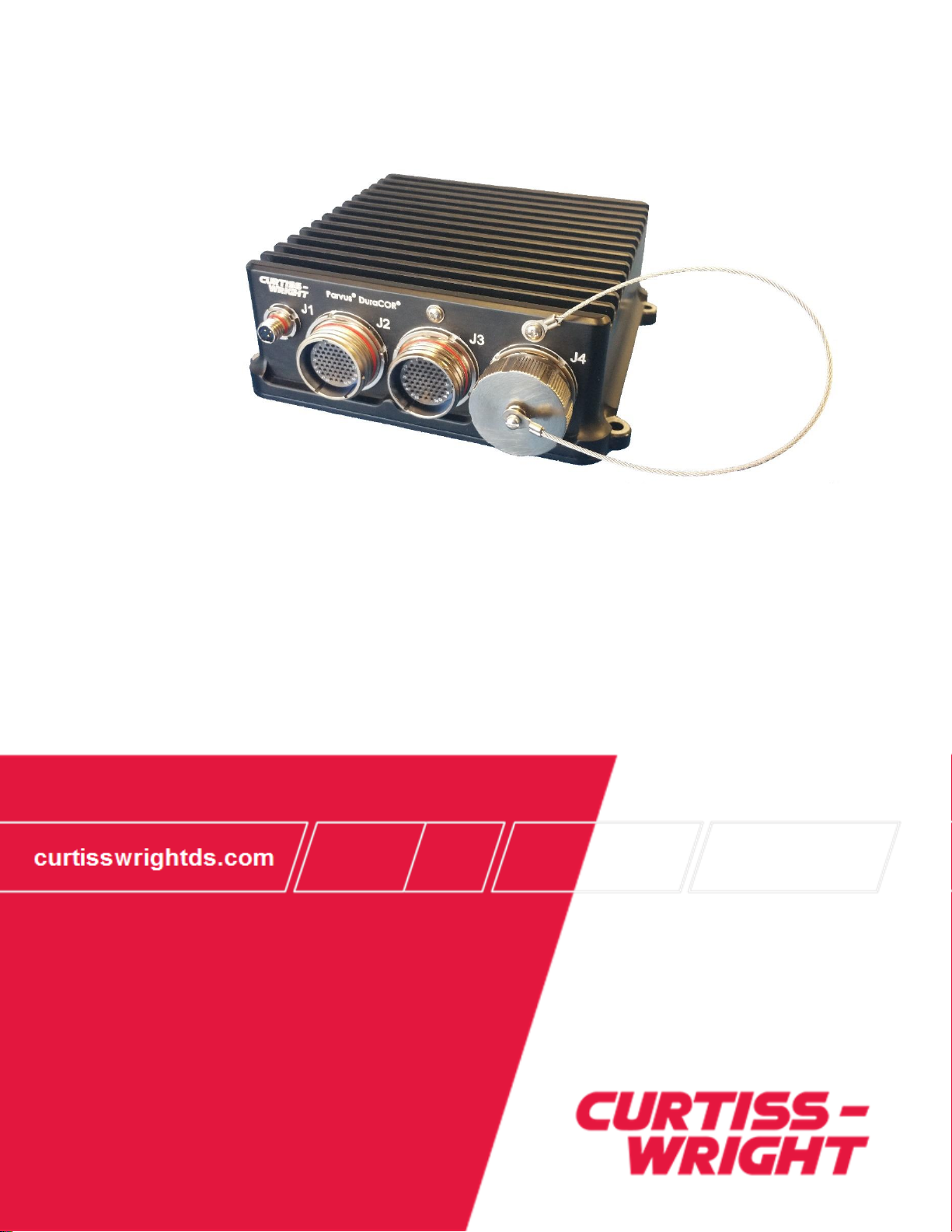
The Parvus® DuraCOR® 312 is an ultra-small form factor (USFF) modular mission computer built around
the high-performance, yet power efficient NVIDIA® Jetson™ industrial Jetson® TX2i “supercomputer-on-
a module” integrated in a miniature rugged chassis with MIL-grade high-density connectors. Combining
powerful NVIDIA Pascal™/CUDA-core GPU signal processing with 64-bit ARMv8 heterogeneous multi-
processing (HMP) for size, weight, power and cost (SWaP-C) sensitive mobile, airborne, ground, manned
and unmanned vehicle and sensor platforms, the unit integrates a massively parallel, many-core
architecture with one of the highest computing FLOPS-per-watt architectures on the market. Thanks to
the unit’s Pascal GPU architecture (supporting Max-Q and Max-P dynamic energy profiles), larger
memory bandwidth, and support for CANbus, the DuraCOR 312 can deliver up to twice the performance
or power efficiency of TX1-based systems together with native vehicle bus interfaces. The unit also
deliver an unparalleled modular system design, boasting multiple Mini-PCIe I/O card slots, high-speed
M.2 internal storage, removable SATA Flash SSD capabilities, and an aerospace-grade power supply
supporting 50ms power hold-up in a fan-less IP67-rated mechanical package designed for wide
temperatures and harsh shock and vibration.
While the low-power DuraCOR 312 is miniature in size, this rugged COTS mission computer LRU packs
performance with six (6) ARMv8 processor cores and 256 Pascal/CUDA-core GPU along with multiple
add-on I/O and storage expansion options to support additional vetronics/avionics interfaces beyond its
already comprehensive set of base I/O (which include Ethernet, CAN, serial, USB, DIO and video ports).
The unit comes with on-board eMMC Flash and supports an optional internal M.2 SSD (NVMe/SATA), as
well as optional removable 2.5” SATA SSD storage for high capacity storage and information assurance
requirements. Like other DuraCOR models, the 312 leverages both an ecosystem of rugged COTS Mini-
PCIe modules (including MIL-STD-1553 and ARINC429 avionics databus interfaces) and Curtiss-Wright’s
responsive, cost-competitive application engineering services to deliver Modified COTS (MCOTS)
variants quickly and without a traditional NRE fee.
With military-grade ruggedization to extend Jetson TX2i operation, the DuraCOR 312 is designed to
operate reliably in extremely harsh environments, making it well suited on-board civil and military aircraft
and vehicle platforms. Comprehensive qualification testing has been performed per MIL-STD-810G, MIL-
STD-461F, MIL-STD-1275D, MIL-STD-704F and RTCA/DO-160G conditions for environmental, power
and EMI (thermal, shock, vibration, dust, water, humidity, altitude, power spikes/surges,
conducted/radiated emissions and susceptibility). In addition, optional 50-ms power hold-up capabilities
are supported for MIL-STD-704F aircraft power switch-over requirements.
Features
Industrial NVIDIA Jetson TX2i supercomputer module
ARMv8, Cortex-A57 (64-bit, 6-core) @ 2GHz+
256-core CUDA Pascal GPU capable of 1.5 TFLOPS 16-bit floating point
Miniature SWaP-optimized form factor:
Small size: ~2.0 x 5.2 x 5.4” (5.2 x 13.2 x 13.6 cm)
Lightweight: 2.14 lb (0.97 kg, configuration C312-0x-100)
Power: ~ 25 W (est.)
Rugged IP67 chassis with micro-mini MIL-performance circular connectors
Modular I/O architecture: up to three add-on Mini-PCIe I/O cards (for avionics and vetronics I/O scalability)
Multiple rugged Flash storage options: eMMC + M.2 SATA/NVMe / removable 2.5” SATA SSD
28 VDC MIL-1275/704/DO-160 power supply for aircraft and ground vehicles; optional 50 ms power hold-
up

DuraCOR 312
Chapter 1 - Introduction
MNL-0670-01 Rev A2
ECO-5931
Effective: 03 Jun 20
Page 11 of 59
Qualified to MIL-STD-810G/DO-160 thermal, shock, vibration, altitude, humidity; also MIL-STD-
461F/DO-160G EMI/EMC
Applications
In-vehicle and airborne rugged mission computing and sensor integration
High-performance embedded computing (HPEC) and general-purpose graphics processing
SWaP-sensitive C4ISR autonomous vehicles, ISR, EW, targeting systems
Configurations
Due to the modularity of the DuraCOR 312 (M.2 / mSATA / Removable SSD and pre-integrated Mini-PCIe
cards), numerous configuration variants are possible. Please consult with your sales representative and
application engineer to assess your technical requirements and recommended system configuration.
Table 1 DuraCOR 312 Standard Configurations
Product Number
Description
C312-00R
DuraCOR 312, NVIDIA Jetson TX2i, 32 GB onboard flash storage, no M.2 / mSATA,
Removable 2.5” SSD storage bay (disk and tray sold separately)
C312-00
DuraCOR 312, NVIDIA Jetson TX2i, 32 GB onboard flash storage, no M.2 / mSATA
C312-01
DuraCOR 312, NVIDIA Jetson TX2i, 32 GB onboard flash storage, 32 GB M.2 storage
C312-03
DuraCOR 312, NVIDIA Jetson TX2i, 32 GB onboard flash storage, 64 GB M.2 storage
C312-04
DuraCOR 312, NVIDIA Jetson TX2i, 32 GB onboard flash storage, 128 GB M.2 storage
C312-05
DuraCOR 312, NVIDIA Jetson TX2i, 32 GB onboard flash storage, 256 GB M.2 storage
C312-06
DuraCOR 312, NVIDIA Jetson TX2i, 32 GB onboard flash storage, 512 GB M.2 storage
C312-07
DuraCOR 312, NVIDIA Jetson TX2i, 32 GB onboard flash storage, 1 TB M.2 storage
Add on, -100
MIL-STD-1553, dual port mini-PCIe card
Add on, -P
50-ms Power Hold-up Option
Base System
The base system integrates a NVIDIA Jetson TX2i module. The base system comes pre-installed with
the Linux 4 Tegra (L4T) with the LTS Linux Kernel on the 32GB onboard flash.

DuraCOR 312
Chapter 1 - Introduction
Page 12 of 59
MNL-0670-01 Rev A2
ECO-5931
Effective: 03 Jun 20
Example ordering code:
C312-03: DuraCOR 312, NVIDIA Jetson TX2i, 32 GB onboard flash storage, 64 GB M.2 storage
Base system with Removable Storage Bay Option
The base system with removable storage bay integrates a NVIDIA Jetson TX2i module. The base system
comes pre-installed with the Linux 4 Tegra (L4T) with the LTS Linux Kernel on the 32 GB onboard flash.
The system also integrates an additional ring to house a removable 2.5” SSD.
Example ordering code:
C312-00R: DuraCOR 312, NVIDIA Jetson TX2i, 32 GB onboard flash storage, no M.2 / mSATA,
Removable 2.5” SSD storage bay (disk and tray sold separately)
System Block Diagram
The block diagram shows the DuraCOR 312 interfaces.
Figure 1: System Block Diagram

DuraCOR 312
Chapter 1 - Introduction
MNL-0670-01 Rev A2
ECO-5931
Effective: 03 Jun 20
Page 13 of 59
Table 2: Chip List
Interface
Description
MFG
MFG Part Number
Processor
Jetson TX2i
NVIDIA
P3489
Ethernet
Broadcom
Broadcom
BCM54610C1IMLG
USB 3.1 Gen 1 to 10/100/1000 Ethernet
Bridge
Microchip
LAN7800
Serial
Dual TXRX RS232/422/485 Multiprotocol
Transceiver
Linear Technologies
LTC2872
USB
4-port USB 2.0 HUB, internal ports
Texas Instrument
TUSB4041IPAPRQ1
4-port USB 3.0 Hub, external ports & EN2
Texas Instrument
TUSB8041IPAPRQ1
Audio
Stereo Codec
Freescale
SGTL5000XNA
Microcontroller
ARM Microcontroller
Freescale
MK60DN512
Shared Resources and Connectors Location
To accommodate different configurations, the following shared resources are explained below:
M.2: The intended use of this socket is primarily M.2 storage (SSD/NVMe) or an additional mini-PCIe
using adapter card.
SATA / mSATA / M.2 (SATA): P3503 and P3503b (SATA power) on the motherboard allow an add-on
SATA drive to be attached to the system via an add-on ring if larger capacities and/or removable storage
is desired. If an added SATA device is attached, the M.2 can no longer be used for SATA storage, but
will retain the NVMe storage and mini-PCIe functionality.

DuraCOR 312
Chapter 1 - Introduction
Page 14 of 59
MNL-0670-01 Rev A2
ECO-5931
Effective: 03 Jun 20
Figure 2: SATA Expansion

DuraCOR 312
Chapter 2 - Quick Start Guide
MNL-0670-01 Rev A2
ECO-5931
Effective: 03 Jun 20
Page 15 of 59
Chapter 2 - Quick Start Guide
This section describes the quick start operational test of the DuraCOR 312.
Recommended Equipment
To use the DuraCOR 312 in the lab environment, the recommended equipment includes:
Appropriate cables, such as CBL-C312
A power source (5A min recommended) applied at connector J1, 9-36VDC input, 28 VDC
nominal. A power cable is included in the breakout cable set.
HDMI monitor, USB keyboard and mouse, other peripheral devices as desired.
Breakout Cable Set
The interfaces and cabling of the DuraCOR 312 can be tested prior to installation in the target system to
ensure full operational capability. Full bench-top testing can be performed by using an appropriate cable
set for this system, such as the CBL-C312 breakout cable set. CBL-C312 is available for purchase from
Curtiss-Wright to support lab or bench testing purposes. A custom set of cables may be made specifically
for the intended target system, vehicle, or craft; refer to Chapter 3 on Connector Descriptions for
connector pinouts and descriptions.
Power-on Sequence
To power on the DuraCOR 312, follow these steps:
1. Connect a power cable to port J1 on the DuraCOR 312 (use the cable from the breakout cable set or
an equivalent power cable)
2. Connect the other end of the power cable to the unpowered DC power source
Caution! Ensure that the DC power source is set to provide 9 to 36VDC (28 nominal) and can
deliver the required power prior to attaching DuraCOR 312.
At 9V the required power is 5A
At 12V the required power is 3.75A
At 28V the required power is 2A
At 36V the required power is 1.5A
3. Connect the remaining cables to the corresponding ports on the DuraCOR 312
J2 –USB, ETH, Audio, etc.
J3 –HDMI, COM ports, GPIO, etc.
J4 –Only required if internal expansion cards have been installed.
4. Connect the HDMI port to a display and turn the display on.
5. Connect all other necessary interface devices (keyboard, mouse, etc.)
6. Apply power.

DuraCOR 312
Chapter 3 - Connector Descriptions
Page 16 of 59
MNL-0670-01 Rev A2
ECO-5931
Effective: 03 Jun 20
Chapter 3 - Connector Descriptions
This chapter identifies the pinouts and signal descriptions for the DuraCOR 312. It also provides
connector part numbers along with suggested mating connector details as necessary.
Connector Identification
Table 3: DuraCOR 312 Connector Identification Table
Receptacle
Use
Receptacle
Label #
# of
Pins
Wire Gauge
(AWG)
Amphenol (Glenair) Jam
Nut Receptacle
Part Number
Amphenol (Glenair)
Mating Connector
Part Number
Power
J1
3
22-28
2M801-033-07M5-3PA
(801-033-07M5-3PA)
2M801-008-16M5-3SA
(801-008-16M5-3SA)
I/O
J2
55
22-28
2M801-033-07M16-55SA
(801-033-07M16-55SA)
2M801-008-16M16-55PA
(801-008-16M16-55PA)
I/O
J3
55
22-28
2M801-033-07M16-55SB
(801-033-07M16-55SB)
2M801-008-16M16-55PB
(801-008-16M16-55PB)
Configurable
I/O Pins
J4
55
22-28
2M801-010-07M16-55SC
(801-010-07M16-55SC)
2M801-008-16M16-55PC
(801-008-16M16-55PC)

DuraCOR 312
Chapter 3 - Connector Descriptions
MNL-0670-01 Rev A2
ECO-5931
Effective: 03 Jun 20
Page 17 of 59
Connector Pinouts
This section provides the pinouts necessary for creating cables to connect to this assembly. If custom
cabling is not designed and built by Curtiss-Wright, all EMI and EMC consideration must be handled by
the customer.
J1 Power Connector
Figure 3: DuraCOR 312 J1 Front Pinout
Table 4: J1 Connector Information
Receptacle
Use
Receptacle
Label #
# of
Pins
Wire Gauge
(AWG)
Amphenol (Glenair) Jam
Nut Receptacle
Part Number
Amphenol (Glenair)
Mating Connector
Part Number
Power
J1
3
22-28
2M801-033-07M5-3PA
(801-033-07M5-3PA)
2M801-008-16M5-3SA
(801-008-16M5-3SA)
Table 5: J1 Pinout
J1 Pin
Signal
A
+VDC
B
VDC_RTN
C
CHASSIS_GND

DuraCOR 312
Chapter 3 - Connector Descriptions
Page 18 of 59
MNL-0670-01 Rev A2
ECO-5931
Effective: 03 Jun 20
J2 I/O Connector
J2 contains 2x GbE ports, 4x USB ports (2x USB 2.0 and 2x USB 3.0), and audio signals. The GbE and
USB ports are ESD protected, however, the audio signals have no ESD protection. Any ESD protection
could compromise the signal quality of the audio signals.
Caution! ESD Sensitive Components
Follow standard ESD and FOD controls to avoid damage to the internal components.
Figure 4: DuraCOR 312 J2 Front Pinout
Table 6: J2 Connector Information
Receptacle
Use
Receptacle
Label #
# of
Pins
Wire Gauge
(AWG)
Amphenol (Glenair) Jam
Nut Receptacle
Part Number
Amphenol (Glenair)
Mating Connector
Part Number
I/O
J2
55
22-28
2M801-033-07M16-55SA
(801-033-07M16-55SA)
2M801-008-16M16-55PA
(801-008-16M16-55PA)

DuraCOR 312
Chapter 3 - Connector Descriptions
MNL-0670-01 Rev A2
ECO-5931
Effective: 03 Jun 20
Page 19 of 59
Table 7: J2 Pinout
J2
Pin
Signal Name
Note
Description
J2
Pin
Signal Name
Note
Description
J2_1
GbE_P2_B_P
Note 1
GbE2
J2_29
USB3_RP1_N
USB3.0 p1 Rx-
J2_2
USB3_RP2_N
USB3.0 p2 Rx-
J2_30
GND
Note 3
USB2.0 p0 Gnd
J2_3
USB3_RP2_P
USB3.0 p2 Rx+
J2_31
USB0_VBUS
Note 3
USB2.0 p0 5V
J2_4
GbE_P2_A_P
Note 1
GbE2
J2_32
GbE_P1_B_P
Note 1
GbE1
J2_5
GbE_P2_B_N
Note 1
GbE2
J2_33
GbE_P1_C_P
Note 1
GbE1
J2_6
USB3_P1_PWR
USB3.0 p1 5V
J2_34
GbE_P1_C_N
Note 1
GbE1
J2_7
USB3_TP2_N
USB3.0 p2 Tx-
J2_35
USB3_RP3_N
USB3.0 p3 Rx-
J2_8
GND
USB3.0 p2 Gnd
J2_36
GND
Audio GND
J2_9
USB3_P2_PWR
USB3.0 p2 5V
J2_37
LINE_IN_L
Audio LineIn L
J2_10
GbE_P2_A_N
Note 1
GbE2
J2_38
AUDIO_GND
Audio Ground,
Analog
J2_11
GbE_P2_C_N
Note 1
GbE2
J2_39
MIC_IN
Audio Mic In
J2_12
USB3_P1_P
Note 2
USB2.0 p1 D+
J2_40
GbE_P1_B_N
Note 1
GbE1
J2_13
GND
USB3.0 p1 Gnd
J2_41
GbE_P1_A_P
Note 1
GbE1
J2_14
USB3_TP2_P
USB3.0 p2 Tx+
J2_42
USB3_RP3_P
USB3.0 p3 Rx+
J2_15
USB3_P2_N
Note 2
USB2.0 p2 D-
J2_43
USB3_P3_N
USB2.0 p3 D-
J2_16
USB3_P2_P
Note 2
USB2.0 p2 D+
J2_44
LINE_IN_R
Audio LineIn R
J2_17
GbE_P2_D_P
Note 1
GbE2
J2_45
LINE_OUT_R
Aud. Line Out R
J2_18
GbE_P2_D_N
Note 1
GbE2
J2_46
LINE_OUT_L
Aud. Line Out L
J2_19
GbE_P2_C_P
Note 1
GbE2
J2_47
GbE_P1_A_N
Note 1
GbE1
J2_20
USB3_P1_N
Note 2
USB2.0 p1 D-
J2_48
USB3_TP3_N
USB3.0 p3 Tx-
J2_21
USB3_RP1_P
USB3.0 p1 Rx+
J2_49
GND
USB3.0 p3 Gnd
J2_22
USB0_OTG_ID
Note 3
USB2.0 p0 ID
J2_50
USB3_P3_P
Note 2
USB2.0 p3 D+
J2_23
USB0_P1_P
Note 3
USB2.0 p0 D+
J2_51
GND
Note 3
Force Recover GND
J2_24
USB0_P1_N
Note 3
USB2.0 p0 D-
J2_52
FORCE_RECOV
#
Note 3
Force Recover Signal
J2_25
GbE_P1_D_P
Note 1
GbE1
J2_53
USB3_TP3_P
USB3.0 p3 Tx+
J2_26
GbE_P1_D_N
Note 1
GbE1
J2_54
USB3_P3_PWR
USB3.0 p3 5V
J2_27
USB3_TP1_N
USB3.0 p1 Tx-
J2_55
GND
Additional GND
J2_28
USB3_TP1_P
USB3.0 p1 Tx+
Note 1) Ground wire not assigned for GbE cables and not required.
Note 2) USB2.0 bidirectional signals embedded in a USB3.0 port.

DuraCOR 312
Chapter 3 - Connector Descriptions
Page 20 of 59
MNL-0670-01 Rev A2
ECO-5931
Effective: 03 Jun 20
Note 3) Port 0 is a stand-alone USB2.0 port with On-the-Go (OTG). Force_Recover puts the nVidia
module into a force-recovery mode to receive new boot-loader and OS software via port 0.
J3 I/O Connector
J3 contains HDMI, RS232/422/483 Serial ports, 8x GPIO signals, CAN ports, Remote on/off, Write
protect, and GPIO
Caution! ESD Sensitive Components
Follow standard ESD and FOD controls to avoid damage to the internal components.
Figure 5: DuraCOR 312 J3 Front Pinout
This manual suits for next models
9
Table of contents
Other Curtiss-Wright Desktop manuals
Popular Desktop manuals by other brands

Compaq
Compaq 7RPK11 7000T Maintenance and service guide

DayStar Digital
DayStar Digital Genesis MP Service guide

Norsk Data
Norsk Data ND-110 COMPACT Operator's guide

HP
HP Vectra XU5 Reference manual

Dell
Dell Precision Tower 7910 owner's manual

Ampro Corporation
Ampro Corporation COREMODULE PCI-104 quick start guide