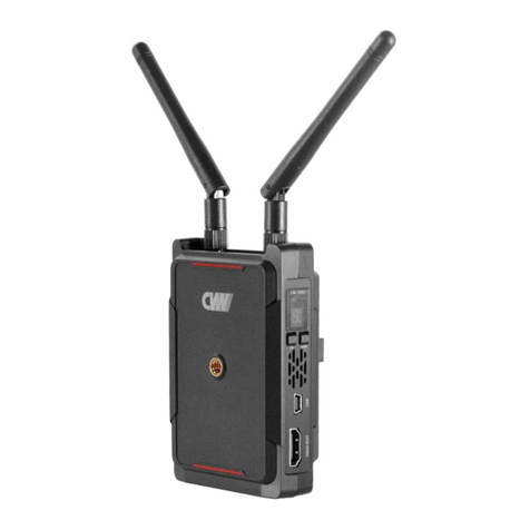
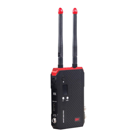
CVW BeamLink-Quad Plus 1U Rack User manual

Full HD
High Definition
Band
5GHz
Range
800m
Ultra Low
Latency
4
Channel
Video
Streaming
IP
Version: 1.0
2023.2.8
BeamLink-Quad Plus 1U Rack
USER MANUAL
This user manual applies to:
Transmitter: 7060*4
Receiver: 6689+3066*1
4-Channel Wireless Video Transmission System
SHENZHEN CRYSTAL VIDEO TECHNOLOGY CO.,LTD
E-mail: Sales@cv-hd.com
Post code:518057
Tel: +86-755-29977913
www.cv-hd.com
Facebook:@crystalvideowireless Instagram: cvwtechnology
ADD: Unit 05-06, Floor 24, Changhong Science & Technology Mansion, Keji 12th Road South,
High-tech Industrial Park, Nanshan District, Shenzhen, P.R. China

Contents
About the User Manual 02
Product Overview
Packing List
02
04
Product Highlights
04
Transmitter
06
10
02
Interfaces and Buttons
Caution 01
03
Receiver
Product Installation
10
12
Installation of Transmitter
14
Installation of Receiver
16
Functional Instructions
18
21
22
Caution
* Avoid exposing this product to direct sunlight for time or using it in dusted long
places
* You must use this product within its temperature and humidity range.
Thank you for purchasing CVW’s wireless HD video transmission system.
Before using this product, please carefully read the following reminders.
* Avoid using this product when it is exposed to vibration and a strong magnetic field.
* Avoid contact of conductive materials with the interior of the product.
* Do not open this product’s enclosure without guidance from a professional at
our company.
Important Reminders
* When installing the magic arm, please fix the transmitter in a direction you want,
then twist the magic arm to fix it on the camera. If you rotate the transmitter to
fix it, the magic arm will not be easily demounted from the transmitter.
* Since the RS232 and Tally interfaces are non-standard physical interfaces, if you
need these functions, please contact our sales staff to confirm.
01
OLED Display Screen
RTSP Streaming Mode Operation
25
26
Video Parameter Settings
Upgrade
System Connectivity Diagram
Troubleshooting
27
31
Product Specifications
Important Reminders

02 03
Packing List
*All the transmitters come with an NP-F battery holder and are preinstalled with a V-mount connector.
Point-to-Point Mode and RTSP Streaming Mode
The system supports point-to-point mode and RTSP streaming mode working
simultaneously, which means that HDMI, SDI, and LAN ports can output video
signals at the same time. In so doing, this solution can be widely applied to
different scenarios.
RS232/422 Transparent Transmission
The RS232/422 port can support the pan-tilt-zoom (PTZ) camera control.
Power Adapter * 1 WiFi Adapter *1
Transmitter * 4
Antenna * 20
Double Ball Head
Magic Arm * 4 SDI Cable * 4
D-Tap to 2-pin
LEMO Cable*4
RS232 Cable * 5
Receiver * 1
Product Highlights
Four channels of transmission only occupy one wireless channel
Supports simultaneous four-channel video and audio signals transmission, and each
video channel’s highest resolution can reach 1080p/60Hz. These channels use the
same wireless channel, greatly saving spectrum resources.
High-quality and low-latency video frame
Supports HD-SDI & 3G-SDI input and output, supports HDMI full HD input and output,
highest resolution can reach 1080p/60Hz. Compared with H.264 technology, H.265
technology offers higher color reproduction, showcasing the image more colorful.
4* 4 MIMO and Beamforming technologies make the wireless beams more concentrated,
signal-to-noise ratio higher, which result in a farther transmission distance and a stronger
interference immunity.
Beamforming
Product Overview
BeamLink-Quad Plus 1U Rack is a multi-channel wireless video transmission system
based on a 5GHz band that supports 4-channel wireless video and audio transmission,
Tally, and pan-tilt-zoom (PTZ) camera control, with video resolution up to 1080p/60Hz.
It is widely used in live streaming, TV and filming, multimedia education, etc.
This instruction manual provides a detailed introduction to this product’s specifications
and an explanation of its interfaces, usage, reminders, and a troubleshooting guide.
Before using this product, please carefully read this instruction manual. If you have any
questions or concerns while using this product, please contact us or our suppliers as
soon as possible.
About the User Manual

TX: 7060
Interfaces and Buttons
A
C
D
E
F
G
H
J
K
L
M
N
N
OLED display
A
BLNA ON/OFF button: High-gain and Low-gain mode switching
CWPS button: pairing
DReset button
E
Network status warning light, yellow light flickers slowly:
network connecting; yellow light is on : network connected;
red light flicker quickly: low battery.
FRS232/422 interface
GSDI input
HHDMI input
IPower switch
JTally output
KLEMO DC input
LBattery slot
MV-mount slot
NAntenna connectors
Introduction to Transmitter’s Interfaces and Buttons
04 05
B
I
Function
Name

06 07
RX: 6689
A
B
C
D
E
F
G
H
A
B
C
D
E
F
H
Reset button
WPS button, pairing
DC input
Power switch
Power indicator:
light on: operating normally;
light off: power off or abnormal
Network status indicator light:
flash: fail to connect the network;
solid: network connected
Mode indicator light
G
LAN port
Function
Name
Introduction to Receiver’s Interfaces and Buttons

RX: 3066
Function Operation Instruction
Short press
the CH or WPS
button
Pairing
Channel switch
Long press the
“CH/WPS” button
for 3 seconds
The displayed
mehod of OLED
screen
Once the channel is switched to a different
channel on the receiver, the transmitter also
will go with it. And the channel will be
displayed on the screen of the transmitter
and receiver.
Long press the
“LNA ON/OFF”
button for 3
seconds
The low gain mode has a good interference
performance, and it is used mainly in a
complex and short-distanced environment
(the screen displays “L”).
Compared with the low gain mode, the high
gain mode shows a weak interference
performance, so it is used in a wide and
long-distanced environment (the screen
does not display “L”).
Low gain and
high gain mode
switch
Once pairing is enabled, “WPS” will be
displayed on the transmitter and receiver’s
OLED screen. Once they pair with each other
successfully, “WPS” will be disappeared on
the OLED screen.
Short press the
“LNA ON/OFF”
button for 1 second
Horizontal screen mode or vertical
screen mode
Restarting one
of the four
channels on
the receiver
Short press the
“RESET” button
to choose the
channel you want
to restart, then
long press it for
3 seconds to
enable this
function.
Once restarting is enabled, “RESET”
will be displayed on the OLED screen.
Once it is restarting successfully,
“RESET” will disappear.
1234
Tally I N
RESET
CH/WPSLNA ON/OFF
OLED Display
RS232/422
HDMI Out
08 09
Power Button
Tally In LAN Port
DC-IN
SDI Out
LAN Port
Introduction to Receiver’s Interfaces and Buttons
Please note that the critical point to pair
them successfully is that both must be in a
pairing situation.

Product Installation
Installation of Transmitter
H D M I
S D I H D M I
3. Please connect the transmitter to the camera with an SDI or HDMI cable.
(as depicted in the diagram)
HDMI input
SDI input
Distance ≥ 1m
Transmitter at a height of
around 1.5 to 2 meters
above the ground
1. Attach the antennas to the transmitter’s antenna connectors. To achieve even better
range performance, all antennas should be arranged in a fan shape. (as depicted in
the diagram)
2. Mount the transmitter on a camera through the screw hole or the V-mount plate.
It is recommeded to hold the camera in a height where it is at least 1.5-2 meters
above the ground. If using multiple transmitters simultaneously, please keep them
at least 1 meter apart. (as depicted in the diagram)
10 11
Distance ≥ 1m Distance ≥ 1m

Installation of Receiver
00:00:00
H D M IH D M IH D M IH D M I
S D I S D I
S D I
S D I S D I
H D M IH D M IH D M IH D M I S D I S D I
S D I
S D I S D I
SDI Out
12 13
1. Mount the WiFi adapter on a tripod, then connect it to the receiver with
a network cable.
*Attach the antennas to the WiFi adapter’s antenna connectors. To achieve even
better range performance, all antennas should be arranged in a fan shape.
(as depicted in the diagram)
2. Please connect the receiver to the switch console or monitor with the SDI or
HDMI cable(s). (The receiver supports 4 SDI outputs and 4 HDMI outputs)
SDI Out
SDI Out
SDI Out
HDMI Out
HDMI Out
HDMI Out
HDMI Out

RX:3066
A
Signal Icon: video signal strength status
B
C
The corresponding transmitter ID: numbered 1, 2, 3, 4 respectively
1
VIDEO
2
VIDEO
3
VIDEO
4
VIDEO
A
D
B
C
CH 1
DChannel: display current channel
WPS L
E
F
EWPS: in pairing status
FGain mode: low gain mode (the screen displays “L”) and
high gain mode (the screen does not display “L”)
Video: video signal input connected
OLED Display Screen
RESET
CH 2
L1
VIDEO
TX:7060
A
BC
D
E
F
Transmitter ID: four transmitters are numbered
1, 2, 3 and 4 respectively
A
BGain mode: low gain mode (the screen displays “L”) and high
gain mode (the screen does not display “L”)
CSignal icon: video signal strength status
D
WPS: pairing
Name Function
EReset: the device is resetting
FCH*: display current channel
Video: video signal input connected
Name Function
14 15

RS232/RS422 Transparent Transmission
Pin
NO. Name Description
NC NC
TXD+ TX data signal
1
2
NC NC
NC NC
3
4
GND
RXD+
5
6
GND
RX data signal
13
2
456
Name Description
RXD-Receive data RX-
NC
TXD-
TXD+Transmit data TX+
GND
RXD+
GND
Receive data RX+
RS232 RS422
Transmit data TX-
NC
Attached: Baud rate settings
Log in to the motherboard parameter settings page to modify the baud rate settings.
For the specific operating steps, please refer to "Video Parameter Settings".
Important reminder: The follwing connector is RS232 by default.
Since there are different RS232/422 interfaces for each switch console on the market,
and each data signal definition of the interface is different too. If you need RS232/RS422
function, please contact our sales staff to confirm and provide them with the model
number of PTZ camera and switch console or the pinout definition of RS232/RS422
interfaces. It will make us easy to customize the RS232/RS422 cables for you. Moreover,
the baud rate will be set ready before delivery.
17
DB9_FEMALE
J15
GP8
GP7
GP6
GP5
GP4
GP3
GP2
GP1
5
9
4
8
3
7
2
6
1
SH1
SH2
Tally Input Interface: DB9 Female Socket
16
Tally Function Instructions
This system’s Tally function interface is factory customized. If you need this function,
please contact our sales staff to confirm the pinout definition of its docking device
and the type of device's interface.
Plug the Tally light into the transmitter's Tally output port, and then connect the
switch console to the receiver's Tally input interface with the customized Tally light
cables. Once all the connections have been completed, the switch console can
control the four transmitters' Tally lights. In so doing, the receiver as a low-level
trigger will be connected to the switch console. The PGM or PVW signal will be
sent to the transmitter from the switch console. Then the transmitter end's Tally
light will be turned on .
The transmitter and receiver’s Tally interfaces : the transmitter’s Tally interface is a
standard 3.5 mm headphone jack and the receiver’s Tally interface is a DB9
female socket.
Tally Light Output Interface
1
2
3
4
5
6
J16
PHONEJACK STEREO SW
RCLamp0521PA
D13
D12
RCLamp0521PA
Tally_Red
Tally_Green
Important Reminders:

18 19
Extend the Transmission
Introduction to Panel Antenna
A panel antenna is a type of directional antenna, which can be used to extend the system’s
transmission range, but the trade-off is that the panel antenna has a transmission angle of
45 degrees.
RTSP Streaming Mode Operation
Using RTSP streaming mode needs software decoding, which means images are
transmitted through the receiver’s LAN port to streaming media software to decode
and display. Moreover, there are many kinds of streaming media existing. The following
description takes VLC media player for example. Once the transmitter and receiver are
connected, the transmitter’s network indicator will be turned on, and the receiver’s
OLED screen will display the signal status. Then connect transmitters to the video
sources, and connect the receiver to RTSP streaming devices through a LAN port.
Take VLC media player for example, after opening VLC, choose “Open Network Stream”,
enter “rtsp://192.168.1.xxx/h265/ch01/main/av_stream”, click “play”, which starts
RTSP streaming.
Important reminder: The IP Address (e.g. the one used by the PC) of the RTSP streaming
device must be on the same network segment as that of the encoding board. Otherwise,
the RTSP streaming mode will not work.
1. Mount the attached bracket on the panel
antenna with screws.
Panel Antenna Usage

20 21
Video Parameter Settings
1. Please make sure that the computer and the receiver remain connected.
3. Input the system’s CODEC address into the corresponding box to enter the
parameter settings page.
2. Set a fixed IP address for the computer and keep it with the system’s IP address
on the same network segment. (192.168.1.XXX).
2. Fix the bracket on the
tripod with screws.
3. Attach the receiver to the bracket through
the V-mount plate with the attached
flexible cables.
4. For the best result, the four transmitters need to move within 45° in front of the
panel antenna.
Panel Antenna
300m
1000m
Decoder
5. This system can transmit up to 1.5-2 kilomters when working with a panel antenna.

22 23
Upgrade
1. The steps of firmware update are the same for both the transmitter and the receiver.
2. The back of the product labeled with the WiFi IP address and the codec board's IP
address. The default IP addresses are as follows:
Wi-Fi IP 192.168.1.201, 192.168.1.202, 192.168.1.203, 192.168.1.204
Transmitter
Encoder IP 192.168.1.111, 192.168.1.112, 192.168.1.113, 192.168.1.114
Wi-Fi IP 192.168.1.100
Receiver
Decoder IP 192.168.1.211, 192.168.1.212, 192.168.1.213, 192.168.1.214
We are using the following diagram as an example. The system’s operating mode,
WiFi address, and encoder/decoder IP address are clearly shown.
Mode:STA
WiFi IP:192.168.1.201
Decode IP:192.168.1.111
Once you have logged in successfully, will the WiFi parameter settings page.
Connect the computer to the receiver's LAN port. Open the browser and input the
WiFi IP address into the address box to enter the login page.

24 25
Select the “Upgrade” option in the “System” box.
On the “Upgrade” settings page, you can upgrade the system’s WiFi module software.
1: Select the latest software package.
2: Click to upgrade.
AP(6689)
System Connectivity Diagram
In a point-to-point mode or RTSP mode, four video resources are sent to the four
transmitters via HDMI or SDI port. Then they were received and sent by the receiver
to the other monitoring devices. See the diagram below:
Camera-1 TX-1
Camera-2
Camera-3
Camera-4
TX-2
TX-3
TX-4
800 m
Four channels of transmission
only occupy one RF channel
RX
Switch Console
Monitor
(LAN Port)
Live Streaming Platforms
SDI/HDMI
4 channels/
Tally/Control
Webcasting Server
Live Streaming Platforms
RTSP Streaming
LAN
Headphone

Product Specifications
Receiver: 3066
Item
Operating Frequency
Antenna Mode
Modulation Mode OFDM
Transmission Power 17dbm (per antenna)
EVM ≤-28dB
Receiving Sensitivity:
≤-70dBm
Wireless Standard 802.11n
Network Encryption WPA2/WPS
Network Mode Point-to-Point private protocol, RTSP protocol
Transmission Distance
Transmission Delay 70ms
Pairing Function Supports pairing
HDMI Protocol Supports HDMI 1.4
Audio Format AAC
Video Compression
Format H.265
Remote Control RS232/RS422
IO Port Signal Return Supports Tally signal return
Interface
SDI input*1; HDMI input*1;
Tally output*1;
Lemo power connector*1;
Antenna connector*4;
Rocker power switch*1;
OLED display screen*1;
Button*3; NP-F970 battery slot*1
Db9 (Tally input)*1’;
Antenna connector*4;
Lemo power connector*1;
Network interface*1;
Power button*1;
Display screen*1;
Functional button*3
Temperature Range
Operating Power Supply DC 12V/2A DC 12V/3A
Operating Voltage Range 7-17V
Power Consumption 20W
Channel Bandwidth 40 MHz
7-36V
10W
5.1~5.8 GHz
Transmitter: 7060
4*4 MIMO, 5dBi External Antenna
800 m/2600 ft ( LoS )
Video Resolution 1080P 23.98/24/25/29.97/30/50/59.94/60, 1080I 50/59.94/60
720P 50/59.94/60
-10 ~ 50°C(Working);-20~80°C(Storage)
Important Reminders
Installation height and interval distance
1) Two conditions need to be met for a transmission distance of 800 meters.
First, orient each antenna to have a clear line of sight. Second, each channel needs
to be set to 4Mbps bitstream.
Gain Mode
You can set LNA at low gain mode in a wide-open line-of-sight environment with a
distance of 300 meters distance. You can set the LNA at high gain mode when you
want to transmit a signal through walls and far away from 300 meters
.
2) To achieve even better range performance, all the transmitters should be at a
distance of 1.5-2 meters above the ground, while the receiver should be at least
2 meters above the ground.
3) When multiple transmitters are used simultaneously, please ensure that they
are at least 1 meter apart.
4) When the receiver and other wireless devices are used simultaneously, please
keep them at least 2 meters apart to prevent possible interference.
26 27

28 29
Channel Settings
1) When one system is in use, it is recommended to set the channel at CH5-CH9.
Because in most Wi-Fi coverage environments, the high and low frequency is
mostly used, while somewhere between is rarely used. The middle frequencies
have low occupancy rates, which effectively avoids co-channel interference.
Once the channel scanning function is enabled, it could quickly help to select
the best possible channel from the available channel list.
2) When two systems are used simultaneously, the receivers must be placed at least
1 meter apart. Once the 80MHz operating mode is enabled, system one is set at
CH5, and system two must be set at CH7, CH8, or CH9. It is recommended to keep
them at least one channel apart. Once the channel scanning function is enabled, it
could quickly help to select the best possible channel from the available channel list.
3) When multiple systems are used simultaneously, the receivers must be placed at
least 1 meter apart. Once the 80MHz operating mode is enabled, system one is
set at CH5, system two is set at CH7, and system three is at CH9. It is recommended
to keep them at least one channel apart. Once the channel scanning function is
enabled, it could quickly help to select the best possible channel from the available
channel list.
Environmental Interference
The following environments will downgrade wireless transmission quality, resulting in
image and audio misalignment (such as image freeze, noise).
1) Walls, large sheets of metal, and various instruments will downgrade wireless transmission.
Try to avoid using this system in these environments.
Cable Connection
2) Please connect the transmitter to the video source with an HDMI cable firstly.
Once the receiver and the monitor are connected, then you can switch them on.
2) Using this system in crowded areas, please place the transmitter and the receiver at a
height of around 1.5 to 2 meters above the ground.
3) If 5GHz wireless devices are used nearby, these may also increase interference. It can
be solved by switching to a different channel manually or automatically.
4) Please do not place this system in a metal container environment, because it will
downgrade wireless transmission. If it is unavoidable, please ensure that each
antenna has a clear line of sight.
1) Please do not hot plug the HDMI cable of the powered system during use.

Installation of Product and Antenna
1) When installing the magic arm, please fix the transmitter in a direction you want,
then twist the magic arm to fix it on the camera. If you rotate the transmitter to
fix it, the magic arm will not be easily demounted from the transmitter.
2) Please install the antennas before powering on the system.
3) To achieve even better range performance, please arrange the antennas to be
fan-shaped and ensure each has a clear line of sight.
30 31
Battery Duration
Take the NPF-970 battery for example, a transmitter with 12W of power
consumption, it will last about 3-4.5 hours.
Important reminder: Depending on the specfic usage, the values may vary slightly.
Troubleshooting
SolutionsProblems
The transmitter
and receiver
are unable to
establish a
connection
1) In short-distance situations, please ensure that the transmitter
and receiver’s antennas are already fully installed, then you must
place them 5 meters apart. With LNA mode being set at low gain
mode, (OLED screen displays the letter “L”, meaning it is in low gain
mode) and when multiple transmitters are used simultaneously,
please ensure that the transmitters are at least 1 meter apart.
2) In long-distance situations, the transmitter is set up on a camera
or handle, it should be set up at 1.5-2 meters above the ground,
and the cameraman’s body should not obstruct the antenna’s
cylinder. The receiver should be set up at least 2 meters above the
ground. The transmission is optimal when the antennas are arranged
to be fan-shaped and have a clear line of sight. With LNA mode
being set at high gain mode (OLED screen does not display the
letter “L”, meaning it is in high gain mode) and when multiple
transmitters are used simultaneously, please ensure that the
transmitters are at least 2 meters apart.
A black screen
is displayed on
the monitor via
receiver output
Suppose the monitor displays a black screen through receiver output
after switching the video source’s video resolution. Please unplug and
plug the transmitter or receiver’s HDMI cable. If unplugging and
plugging an HDMI cable does not make the system work normally,
please restart the transmitter and receiver.

The monitor
displays a
mosaic or lag
No video output
when connecting
a receiver to a
switch console
or monitor
Please confirm if the transmitter and receiver’s OLED screen displays
the signal icon and the word ”VIDEO”. If there is no signal icon, it
indicates that the network is not connected. please refer to the first
problem’s solution of troubleshooting. If there is a signal icon, but the
transmitter’s OLED screen does not display the word “VIDEO”,
please check the video source and the connected SDI/HDMI cable.
If the transmitter and receiver have a signal icon and a word “VIDEO”,
but the switch console displays nothing, please check the SDI/HDMI
cable that is connected to the switch console, and change the
camera’s video output resolution to 1080i50 or 720p50, then test it.
In addition, connect the receiver to other monitor with the SDI/HDMI
cable to test them.
The display is
flickering green
when the receiver
outputs video signal
to the monitor
The HDMI cable has not been firmly plugged in the transmitter or
receiver’s HDMI port or has not been firmly plugged in the camera’s
HDMI port. Please unplug and plug the HDMI cable or change it to
another HDMI cable.
SolutionsProblems
32 33
1) Within a 300 meters range, LNA mode is set at low gain mode
(OLED screen displays the letter “L”, meaning that it is in low
gain mode).
2) When multiple transmitters are used simultaneously, please
ensure that the transmitters are at least 1 meter apart.
3) The transmitter is set up on a camera, it should be set up at 1.5-2
meters above the ground, and the cameraman’s body should not
obstruct the antennas. The receiver should be set up at least 2
meters above the ground, and the antennas are fan-shaped, and
each has a clear line of sight.
4) The working channel is set between CH5-CH9.
5) In a range exceeding 300 meters or when needing to transmit a
signal through walls, please set the transmitter and receiver to
high gain mode.
6) If multiple systems are used simultaneously, please keep their
receivers at least 2 meters apart.
7) If a wireless broadcasting and communication system is used on
set, please keep the broadcast and communication host and the
CVW receiver at least 2 meters apart.
SolutionsProblems
Table of contents
Other CVW Microphone System manuals
Popular Microphone System manuals by other brands

Better Music Builder
Better Music Builder VM-93C G2 operating instructions

Audio Technica
Audio Technica ATW-1951 Installation and operation

Redback
Redback C 8881A operating instructions

Electro-Voice
Electro-Voice REV Specification sheet

Sennheiser
Sennheiser MKE 440 quick guide

RODE Microphones
RODE Microphones WIRELESS GO user manual