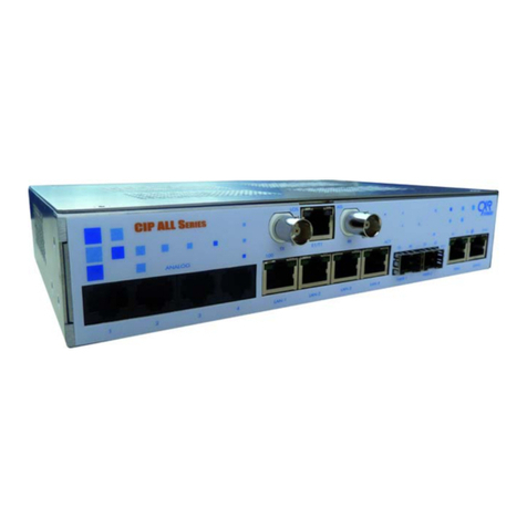
CXR 54500-16 User manual

CXR Larus Corporation
Company Manual 80-100-400
Issue 1, July 2006
www.cxrlarus.com
CXR Larus Corporation
894 Faulstich Court
San Jose, CA 95112
Tel (408) 573-2700
StarClock 200E
Model 54500 System Shelf
T1/E1 Synchronization Timing System
VOLUME 1
System Description
This manual applies to the following equipment:
Model Model
54500-16 54541-2
54500-17 54542-2
54501-1 54550-21
54502-1 54550-22
54505-0 54550-23
54510-0 54550-24
54510-1 54560-2
54511-2 54560-3
54512-3 54571-2
54512-4 54572-3
54513-3 54573-2
54513-4 54574-2
54513-5 54575-5
54514-0 54577-1
54514-1 54580-2
54522-5 54591-2
54523-3 54593-2

CXR Larus Corporation
Company Manual 80-100-400
Issue 1, July 2006
www.cxrlarus.com
CXR Larus Corporation
894 Faulstich Court
San Jose, CA 95112
Tel (408) 573-2700
© Copyright 2006

Volume 1 Contents
__________________________________________________________________
section topic page
1. Introduction 1-1
1.1 General 1-1
1.2 System Description 1-2
1.3 Versions 1-4
1.31 Stratum 3E/LNC System 1-7
1.32 Stratum 2/TNC System 1-7
1.33 Stratum 1/PRC System 1-7
1.34 General GPS Information 1-9
1.35 Track and Hold Clock Card Combinations 1-10
1.36 Characteristics Common to All Systems 1-11
1.4 Cards 1-11
1.5 Features 1-14
1.6 Options 1-15
1.7 Installation Advice 1-17
2. Applications 2-1
2.1 General 2-1
2.2 Timing Distribution and Central Clock Considerations 2-2
2.21 Synchronization Networks 2-2
2.22 Interoffice Distribution 2-7
2.23 Intraoffice Distribution 2-11
2.24 SONET and SDH Network Elements 2-12
2.25 T1 References 2-13
2.26 E1 References 2-13
3. Specifications 3-1
3.1 General 3-1
3.2 StarClock 200E Mounting Elements 3-1
3.21 Model 54500 Mounting Shelf 3-1
3.22 Environmental Limitations 3-1
3.3 Cards 3-3
3.31 Model 54511 T1 Input Card 3-3
3.32 Model 54512 E1/2.048 MHz Input Card 3-6
3.33 Model 54513 CC/5 MHz/10 MHz Input Card 3-10
3.34 Model 54522 Stratum 3E/LNC Track and Hold Clock Card 3-13
3.35 Model 54523 Stratum 2/TNC Track and Hold Clock Card 3-20
3.36 Model 54591 GPS Stratum 1/PRC Track and Stratum
3E/LNC Hold Clock Card 3-27
3.37 Model 54593 GPS Stratum 1/PRC Track and Stratum 2/TNC
Hold Clock Card 3-35
3.38 Model 54541 T1 Synchronization Monitor Card 3-43
3.39 Model 54542 E1/2.048 MHz Square Wave Synchronization
Monitor Card 3-48
3.40 Model 54550 Information Management Card 3-54
3.41 Model 54560 Alarm Interface Card 3-58
3.42 Model 54571 T1 Output Driver Card 3-61
3.43 Model 54572 Composite Clock Output Driver Card 3-64
3.44
Model 54573 E1 and 54574 2.048 MHz Square Wave 3-72

5 5 RS-422 Output Driver Card 3
7 5/10 MHz Output Driver Card 3
Shelf) 3
Output Driver Cards
3.4
3.4 Model 5457
Model 5457 -76
-79
6
3.47 Model 54500E Backplane (of -82
4. Operation 4-1
4.1 General 4-1
4.2 Operation from Front Panels 4-1
4.21 Hold Mode Track and Hold Card Tests
Selection of C 4-1
4.22 lock Source for Output Driver Cards 4-2
Interface Card
2 Synchronization
4.25 ing of Card Outputs 4-5
593TrackandHoldClock
rmation Management Card
3 erface Card
4577 Output Driver Cards
orts
4.23 Alarm Cutoff on 54560 Alarm 4-4
4.24 Selection of DS1/E1 Input for 54541/5454
Monitor Card
Monitor
4-4
4.3 StarClock 200E System Self Diagnostics 4-6
4.31 Model 54522, 54523, 54591, and 54
Cards 4-6
4.32 Model 54550 Info 4-6
4.3
4.3 Model 54560 Alarm Int
Model 54571 through 5 4-6
4-6
4
4.35 Failure Rep 4-7
5. Circuit Descriptions
Card
ld Clock Card
5.62 5-20
ation, 54522 and 54523 Cards
tratum 1/PRC Track and Stratum
5.81 Functions 5-27
cription
tratum 1/PRC Track and Stratum 2/TNC
Card
ent Card
5-1
5.1 General 5-1
5.2 Backplane 5-1
5.21 Functions 5-1
5.22 Circuit Description 5-1
5.3 Model 54511/54512 Input 5-4
5.31 Functions 5-4
5.32 Circuit Description 5-5
5.4 Model 54513 Input Card 5-6
5.41 Functions 5-6
5.42 Circuit Description 5-6
5.5 Model 54522 Stratum 3E/LNC Track and Hold Clock Card 5-11
5.51 Functions 5-11
5.52 Circuit Description 5-12
5.6 Model 54523 Stratum 2/TNC Track and Ho 5-19
5.61 Functions
Circuit Description 5-19
5.7 Clock Oper 5-25
5.8 Model 54591 GPS S
3E/LNC Hold Clock Card 5-27
5.82 Circuit Des 5-29
5.9 Model 54593 GPS S
Hold Clock Card 5-35
5.91 Functions 5-35
5.92 Circuit Description 5-36
5.10 Model 54541/54542 Synchronization Monitor 5-42
5.101 Functions 5-52
5.102 Circuit Description 5-42
5.11 Model 54550 Information Managem 5-48
5.111 Functions 5-49
5.112 Circuit Description 5-49
5.12 Model 54560 Alarm Interface Card 5-53

1 T1 Output Driver Card
5.14 Composite Clock Output Driver Card 5-60
uare Wave Output
s
5 RS-422 Output Driver Card
5.17 7 5/10 MHz Output Driver Card 5-72
5.18 s54571,54572,54573,54574OutputCard Redundancy
5-75
81 5
utputs Installed in a StarClock 200E 5
5.121 Functions 5-53
5.122 Circuit Description 5-53
5.13 Model 5457 5-57
5.131 Functions 5-57
5.132 Circuit Description
Model 54572 5-57
5.141 Functions 5-60
5.142 Circuit Description 5-60
5.15 Model 54573 E1 and 54574 2.048 MHz Sq
Driver Card 5-64
5.151 Functions 5-64
5.152 Circuit Description 5-65
5.16 Model 5457 5-69
5.161 Functions 5-69
5.162 Circuit Description
Model 5457 5-69
5.171 Functions 5-72
5.172 Circuit Description
Model 5-72
Switching
Functions
5.1 -75
5.19 Output Cards With 10 O
shelf -78
6-16. Warranty
ppendix
AA vs. AB Architecture A-1
Appendix
B System Behavior: Phase Alignment
AB-1
G-1
um
A
A
Glossary
Vol e 1 Figures
section topic pa
1-3 tarClock 200E Front Panel Layout 1-8
2-2 k 200E Stratum 2/TNC Application Diagram (54523) 2-4
1/3E or PRC/LNC Application Diagram
pplication Diagram
3-3 t Card Front Panel 3-11
3-5 Stratum 2/TNC Track and Hold Clock Card 3-22
atum 3E/LNC
Stratum 2/TNC Hold
ge
1-1 StarClock 200E Front View 1-2
1-2 StarClock 200E System Block Diagram
Typical S 1-3
2-1 StarClock 200E Stratum 3E/LNC Application Diagram (54522)
StarCloc 2-3
2-3 StarClock 200E Stratum
(54591) 2-5
2-4 StarClock 200E Stratum 1/2 or PRC/TNC A
(54593) 2-6
2-5 Central Clock Concept 2-8
3-1 Model 54511 T1 Input Card Front Panel 3-4
3-2 Model 54512-4 E1 Input Card Front Panel
Model 54513 Inpu 3-7
3-4 Model 54522 Stratum 3E/LNC Track and Hold Clock Card
Model 54523 3-14
3-6 Model 54591 GPS Stratum 1/PRC Track and Str
Hold Clock Card 3-29
3-7 Model 54593 GPS Stratum 1/PRC Track and 3-37

itor Card
rd
3
r Card 3
ard 3
Square Wave Output Driver Card
5-2 12 Input Card 5-6
5-4 Stratum 3E/LNC Track and Hold Clock Card 5-13
Card
m
rack and Stratum 3E/LNC
m 2/TNC Hold
rd
e Clock Output Driver Card 5
t Driver Card 5
Hz Square Wave Output Driver Card 5
t Driver Card 5
Model 54577 5/10 MHz Output Driver Card 5-74
8 Installation of a 10-output card into a StarClock 200E shelf 5-78
Architecture A-3
A-3
1 Clock State Diagram G-2
G-2 G-3
V e 1
Clock Card
3-8 Model 54541 T1 Synchronization Mon 3-44
3-9 Model 54542 E1/2.048 MHz Synchronization Monitor Card 3-51
3-10 Model 54550 Information Management Ca 3-55
3-11 Model 54560 Alarm Interface Card 3-60
3-12 Model 54571 T1 Output Driver Card -62
3-13 Model 54572 Composite Clock Output Drive -66
3-14 Model 54573 E1 Output Driver C -73
3-15 Model 54574 2.048 MHz 3-74
3-16 Model 54575 RS-422 Output Driver Card 3-77
3-17 Model 54577 5/10 MHz Output Driver Card 3-80
4-1 Clock Auto-selection State Diagram 4-3
5-1 StarClock 200E Mounting Shelf Backplane
Model 54511/545 5-2
5-3 Model 54513 Input Card
Model 54522 5-10
5-5 Model 54523 Stratum 2/TNC Track and Hold Clock 5-21
5-6 Model 54591/54593 Card GPS Mode Algorith 5-28
5-7 Model 54591 GPS Stratum 1/PRC T
Hold Clock Card 5-30
5-8 Model 54593 GPS Stratum 1/PRC Track and Stratu
Clock Card 5-37
5-9 Model 54541/54542 Synchronization Monitor Card 5-44
5-10 Model 54550 Information Management Ca 5-51
5-11 Model 54560 Alarm Interface Card 5-56
5-12 Model 54571 T1 Output Driver Card 5-59
5-13 Model 54572 Composit -63
5-14 Model 54573 E1 Outpu -66
5-15 Model 54574 2.048 M -67
5-16 Model 54575 RS-422 Outpu -71
5-17
5-1
A-1 AA Clock
A-2 AB Clock Architecture
G- Wander Generation (MTIE)
olum Tables
section topic page
1-A Card Function and Identification 1-12
2-A T1 Clock Strata Performance 2-9
2-B E1 Clock Performance 2-10
4-A Alarm Thresholds 4-8
ritized Synchronization Status Messages 5-18
5-A Prio

[This page is intentionally left blank.]

__________________________________________________________
CXR Larus 80-100-400 Issue 1, July 2006 1-1
1 Introduction
_
____________________________________________________________________
1.1 General
1.11 This document is Volume 1 of this series of manuals and describes the CXR
Larus StarClock 200E Expandable T1/E1 Synchronization Timing System and
its theory of operation. This is the expandable version of the system which
uses the Model 54500 shelf is shown in Figure 1-1. This volume isintended for
planners, engineers, and general users.
Installation and operation information for the StarClock 200E relating to
planning and engineering may be found in Volume 2, CXR Larus Manual
80-600-400. It describes backplane wiring, switch settings, testing,
maintenance, and troubleshooting of the system, and is intended for use by
field support engineers, technicians, and craft personnel.
Volume 3, Manual 80-800-400, the Model 54550 Information Management
Card TL1/ITL1 User Manual, provides a discussion of the domestic and
international transaction language used by the system. It also covers
performance monitoring, parameter descriptions,and security commands, and
is intended for use by Control Center personnel. It is recommended that the
TL1/ITL1 operator read this document in its entirety before using the system.
Volume 4, Manual 80-801-400, the Model 54550 Information Management
Card Menu User Manual, provides a discussion of the Windows-based user
interface to the system. It also covers performance monitoring, parameter
descriptions,andsecuritycommands,andisintendedforuse byControlCenter
personnel. It is recommended that the menu operator read this documentinits
entirety before using the system.
NOTE:
StarClock 200E is factory provisioned with either the TL1/ITL1 or menu user interface.

CXR Larus 80-100-400
Issue 1, July 2006
___________________________________________________________
__________________________________________________________
CXR Larus 80-100-400 Issue 1, July 2006 1-2
Figure 1-1 StarClock 200E Master Shelf Front View
1.12 The StarClock 200E is an expandable and modular system packaged in a
Network Equipment Building System (NEBS) compatible19/23-inch (48.2/58.4
cm) rack mounting shelf, Model 54500-16 for the E1 application or Model
54500-17 for the T1 application. The shelvescontain backplanes that receives
all source signals and distributes them to the appropriate cards for processing.
The processed signals from the cards are delivered to the appropriate pins or
connectors on the shelf backplane. The StarClock 200E master shelf system
block diagram is shown in Figure 1-2 and the backplaneis described inSection
5.

__________________________________________________________
CXR Larus 80-100-400 Issue 1, July 2006 1-3
NOTE: many of the output cards have twenty outputs each
Figure 1-2 StarClock 200E Master Shelf System Block
Diagram

CXR Larus 80-100-400
Issue 1, July 2006
___________________________________________________________
__________________________________________________________
CXR Larus 80-100-400 Issue 1, July 2006 1-4
1.2 System Description – Master shelf
1.211 The StarClock 200E provides an accurate and reliable way to synchronize
communicationnetworkelements(NEs)throughoutabuildingand, with the use
of additional equipment, throughout a communication network. By
synchronizing all the equipment, especially switching and multiplexing NEs,
acrossanetwork,ausercanmaximizetheutilizationofnetworkequipmentand
minimize network transmission errors.
1.212 StarClock 200E systems contain one or twotrack and holdclock cards. If there
are two, it is highly recommended that they be of the same holdover stratum
level. Each of these cards contains a direct digital frequency synthesizer
(DDFS) whose output is available for use by output driver cards to produce
timing signals for other pieces of network equipment. Each DDFS uses a 10
MHz reference. The 10 MHz reference comes from an on-board oscillator,
either ovenized crystal or rubidium depending on the stratum (timing) level.
The DDFS is made to follow or "track" an input reference by comparing the
output with the input and making suitable correction to the frequency
synthesizer.
1.213 In Stratum 1 (T1) or Primary Reference Clock (E1) systems, the input tracking
reference is derived from a set of cesium beam atomic clocks aboard orbiting
Global Positioning System (GPS) satelliteswhosesignalsaretransmittedto an
on-board GPS receiver. As a result, external input references are not required
for normal operation. However, the Stratum 1 or PRC track and hold cards do
have tracking reference inputs that permit them to be operated as Stratum
2/Transit Node Clock (TNC) or 3E/Local Node Clock (LNC) cards, depending
on the model, if there is a GPS failure.
1.214 A GPS failure could be caused by damage to the external GPSantenna or the
cabling between the GPS antenna and the main timing shelf or by failure of the
on-board GPS receiver itself. Excessive amounts of jitter can also cause a
GPS failure during GPS warmup.
1.215 The Stratum 2/TNC and 3E/LNC systems (and Stratum 1/PRC with GPS
failure) use external signals as tracking references. Track and hold cards at
each level can acquire and track signals that meet the requirements of the
same or higher (more precise) level. Normally, Digital Signal Level 1 (DS1),
E1, or Composite Clock signals traceable to a Stratum 1 or PRC source should
be used. The output of a StarClock 200E Stratum 2/TNC or 3E/LNC system
that has references from Stratum 1/PRC sources will meet Stratum 1/PRC
requirements.

__________________________________________________________
CXR Larus 80-100-400 Issue 1, July 2006 1-5
1.216 Each track and hold card has provision for two DS1, E1, or CC tracking
reference inputs, one primary and one secondary, and contains circuitry to
remove jitter and wander from the input signal being tracked. If a StarClock
200E system loses its active tracking reference, the cards switch to holdover
mode where the digital frequency synthesizer continues to run at the last
setting before the reference was lost. Frequency accuracy in holdover
determines the timing level of the various track and hold card models. After a
track and hold card switches into holdover mode, it attempts to acquire and
track the reference signal at its secondary tracking input. If it is successful, the
card will continue normal operation.
1.217 Two input architectures are available for StarClock 200E systems with two
54522 or 54523 track and hold cards. The AA input architecture has both cards
using the same source as the primary DS1/E1 tracking reference and another
source for the secondary tracking reference. The AB input architecture uses
one source as primary on one card and the other source as secondary. The
other card reverses the references so that each DS1/E1 source is primary on
one track and hold and secondary on the other. The 54591 and 54593 GPS
track and hold cards provide only the AB input architecture. AB architecture is
the dominant choice in North America. AA architecture is used in some
international locations.
1.218 The StarClock 200E track and hold clock cards have phase alignment circuitry
that causes the secondary input track and hold card to attempt continually to
align its output phase with the primary card, regardless of the reference being
tracked. Thus, an input switch by the output driver cards from one input track
and hold card to the other will cause a minimal phase change at the outputs.
1.219 The StarClock 200E is nonrevertive which means that, if the primary DS1, E1,
or CC reference fails and the track and hold card(s) switches to use the
secondary input, the card(s) will not switch backto use the primaryinputunless
the secondary input fails or a Switch Inputs command is sent from the terminal
or PC.
1.220 As another alternative, the StarClock 200E track and hold cards can be
commanded to use an external 5 or 10 MHz source as a tracking reference. A
suitable source could come from a cesium beam clock, an external GPS
receiver, a LORAN-C receiver, or similarprecision source. The accuracyof the
outputs from a StarClock 200E system in this configuration is related to the
accuracy of the external 5 or 10 MHz source.
1.221 If a track and hold card has never been in tracking mode since it was powered
up, there is no information available to set the frequency synthesizer for
holdover mode. In this case, the frequency synthesizer is set to run at the
nominal default frequency. This mode is called free run. Since there is no
reference available to compare to the output frequency in free run, the output
frequency could be farther off-frequency than in holdover.

CXR Larus 80-100-400
Issue 1, July 2006
___________________________________________________________
__________________________________________________________
CXR Larus 80-100-400 Issue 1, July 2006 1-6
1.222 Each of the output driver cards can select from four inputs, one from each of
the input track and hold cards and one from each DS1, E1, or CC input
reference directly. Logic on each output driver card selects the "best" timing
source. A timing signal from a track and hold card that is tracking an input
reference is "better" than a timing signal from a card that is in holdover. By the
same token, a timing signal from a track and hold card in holdover mode is
"better" than a reference input signal. If at any time a "better" signal source
than the one in use becomes available, the output driver cards will switch to
use the better source. The output driver cards contain circuitry to limit the rate
of output phase change after a switch. The first track and hold cardto achieve
tracking mode is selected as the primary card. Circuitry on each output driver
card causes all output cards to select the same timing reference as the
left-most output driver card in the shelf. Most output driver cards produce
twenty output signals each with the exception of Models 54575 and 54577.
1.223 StarClock 200E master shelf can contain auxiliary cards that measure the
performance of the system, provide indication of hardware failures,and furnish
command and status interfaces to the system.
1.224 StarClock200Eprovidesfunctional fault tolerance in anumberofways,offering
redundant track and hold cards with dual DS1, E1, or CC inputs and provision
for multiple (up to ten) output driver cards, for example. Since many pieces of
network equipment have two timing inputs, an output from each of two output
driver cards from one StarClock 200E should be connected.
1.225 Another feature is individual DC-to-DC converters on each card. This removes
a common power supply as a single point of failure. Failure of one DC-to-DC
converteraffectsonlyonecard. Criticalcomponentslikethetrackandholdand
output driver cards can be redundant so that a failure of one does not cause a
loss of service in the network equipment.
1.226 Failure ofan auxiliary card doesnot affecttheprimarysystem function, which is
to produce accurate timing signals.
1.227 Failures are categorized into major, indicating a loss of service, and minor,
indicating a loss of function. StarClock 200E provides means whereby major
and minor alarms can be connected to indicatorsto summon servicepersonnel
for timely repair.

__________________________________________________________
CXR Larus 80-100-400 Issue 1, July 2006 1-7
1.3 Versions
1.301 StarClock 200E can accept either oneortwoframedDS1,E1,orCCsignalsas
input references. From these and other inputs, timing is extracted and used to
discipline the oscillator on each clock card. The CXR Larus StarClock 200E
system is available in six versions: Stratum 3E or LNC, Stratum 2 or TNC, and
Stratum 1 or PRC. Figure 1-3 shows a front panel layout of a typical StarClock
200E system with several output cards.
1.31 Stratum 3E/LNC System
1.311 A redundant StarClock 200E Stratum 3E or LNC system requires a
54500-17 (T1) or 54500-16 (E1) mounting shelf with backplane, two 54511-2
T1 or 54512 E1/2.048 MHz or 54513 Input Cards, two 54522 Track and Hold
Clock Cards equipped with ovenized crystal oscillators, and up to ten output
driver cards consisting of any mix of T1 (54571-2), CompositeClock (54572-3),
European Standard (E1) all ones (54573-4), 2.048 MHz Square Wave (54574-
2), 1.544 MHz EIA RS-422 Square Wave (54575-4),8kHzEIARS-422Square
Wave (54575-5), and 5/10 MHz (54577).
1.312 The system may also include one or two 54541-2 T1 or 54542-3 E1 cards for
synchronization measurements, one 54550-21, -22, -23, or -24 Information
Management Card with either TL1/ITL1 or menu interface, and one 54560-3
Alarm Interface Card.
1.32 Stratum 2/TNC System
1.321 A redundant Stratum 2 or TNC system includes a 54500-17 (T1) or 54500-16
(E1) mounting shelf, two 54511-2 T1 or 54512 E1/2.048or 54513 Input Cards,
and two 54523 Track and Hold Clock Cards equippedwith rubidium oscillators.
Up to ten output driver cards may be selected, consisting of any mix of T1
(54571-2), Composite Clock (54572-3), European Standard (E1) all ones
(54573-4),2.048MHzSquareWave(54574-2),1.544MHz EIARS-422Square
Wave (54575-4), 8 kHz EIA RS-422 Square Wave (54575-5), and 5/10 MHz
(54577) cards.
1.322 The system may also include one or two 54541-2 T1 or 54542-3 E1 cards for
synchronization measurements, one 54550-21, -22, -23, or -24 Information
Management Card with either TL1/ITL1 or menu interface, and one 54560-3
Alarm Interface Card.

CXR Larus 80-100-400
Issue 1, July 2006
___________________________________________________________
__________________________________________________________
CXR Larus 80-100-400 Issue 1, July 2006 1-8
Figure 1-3 Typical StarClock 200E Front Panel Layout

__________________________________________________________
CXR Larus 80-100-400 Issue 1, July 2006 1-9
1.33 Stratum 1/PRC System
1.331 A redundant Stratum 1 or PRC system is made up of a 54500-17 (T1) or
54500-16 (E1) shelf, two 54511-2 T1 or 54512 E1/2.048 MHz or 54513 Input
Cards, and either two 54591 GPS Track and Hold Clock Cards or two 54593
GPS Track and Hold Clock Cards. Up to ten output driver cards may be
selected, consisting of any mix of T1 (54571-2), Composite Clock (54572-3),
European Standard (E1) all ones (54573-4), 2.048 MHz Square Wave (54574-
2), 1.544 MHz EIA RS-422 Square Wave (54575-4),8kHzEIARS-422Square
Wave (54575-5), and 5/10 MHz (54577) cards. A Network Time Server Card
(54580) is available as an option only with the GPS system.
1.332 The system may also include one or two 54541-2 T1 or 54542-3 E1 cards for
synchronization measurements, one 54550-21, -22, -23, or -24 Information
Management Card with either TL1/ITL1 or menu interface, and one 54560
Alarm Interface Card.
1.333 The 54591-2 and 54593-2 GPS cards are provisioned with AB input
architecture only. AA input architecture is not supported with GPS. Track and
hold cards in any combination must provide the same input architecture, either
AA or AB.
1.34 General GPS Information
1.341 The 54591 and 54593 cards incorporate a GPS receiver and timing processor.
The receiver normally requires a rooftop antenna to furnish adequate signal
strength for dependable reception and tracking. The antenna should be
located for the 'best view of the sky.' The antenna cable connects tothe rear of
the 54500 shelf at the GPS antenna connector. Inside the shelf, the coax is
routed to the GPS receiver unit within the 54591/54593 GPS card.
1.342 The standard antenna kit contains the following:
· GPS antenna [weatherproof and less than 5 inches (13 cm) in height]
· Vertical surface mounting bracket with hardware
· 50 feet (15 meters) of RG-58 coaxial cable with connectors
1.343 TheGPSreceiver uses a sophisticated technology whichsimultaneouslytracks
signals from multiple nongeostationary communications satellites. The U.S.
militaryoriginallymandatedthisglobalsystem primarilyfor precision navigation.
Its secondary role is that of an accurate frequency source. The U.S. military
maintains daily calibration of the primary frequency reference, an atomic clock
traceable to Coordinated Universal Time (UTC), in each healthy satellite.

CXR Larus 80-100-400
Issue 1, July 2006
___________________________________________________________
__________________________________________________________
CXR Larus 80-100-400 Issue 1, July 2006 1-10
1.344 The GPS radio receiver internal to the CXR Larus 54591/54593 module
receivesandcomparessignalsfromthesesatellitesandprocessesa result,not
in terms of a precise location but in terms of a precision frequency, since it
assumes that the installation has a fixed location on earth. It tracks up to eight
satellites in the sky and can use signals from at least three satellites to
triangulate a location, with a fourth satellite to check on the first three. Using
the fourth, the receiver can calculate and compensate for clock errorby solving
four simultaneous equations (one for each satellite measurement). The output
of the GPS radio receiver, a stable reference of exactly one pulse per second
(1PPS), is then used by the Precision Time Assembly. The Precision Time
Assembly compares this 1PPS with the on-board frequency reference of the
54591/54593 to develop a time correction factor for the precision oscillator.
1.345 A GPS failure can be caused by damage to the GPS antenna or cable and
excessive amounts of jitter can cause loss of GPS tracking. The 54591
includesanovenizedcrystaloscillatorforStratum3E/LNCperformanceinHold
in the event of loss of GPS tracking. The 54593 includes a rubidium oscillator
for Stratum 2/TNC Hold performance in the event of loss of the GPS primary
reference. The internal oscillators allow the 54591 and 54593 to ignore
short-term GPS tracking loss.
1.35 Track and Hold Clock Card Combinations
1.351 The following combinations of track and hold cards are acceptable. Each card
must be paired with a 54511 T1 or 54512 E1/2.048 MHz Input Card.
Stratum 1/PRC (GPS) Two 54591-2* cards,
with Stratum 3E/LNC Hold: or
One 54591-2* and
one 54522-5* card
Stratum 1/PRC (GPS) Two 54593-2* cards,
with Stratum 2/TNC Hold: or One 54593-2* and
one 54523-3* card
Stratum 3E/LNC: Two 54522-5* cards
Stratum 2/TNC: Two 54523-3* cards
* Provides AB input architecture.

__________________________________________________________
CXR Larus 80-100-400 Issue 1, July 2006 1-11
1.36 Characteristics Common to All Systems
1.361 The maximum number of outputs for the master shelf is 200. These can be
arranged in a maximum of 100 protected pairs (even and odd) so that, if any
one output fails, the other output of the pair will still be valid and downstream
network elements are still timed. Alarm and status reporting, performance
monitoring, and operation support system (OSS) interface are provided by the
54541/54542, 54550, and 54560 cards. These support cards are not mission-
critical to basic timing, so they are never redundant.
1.362 The maximum number of outputs utilizing a master shelf and a 54510
expansion shelf is 558. Utilizing eight expansion shelves, up to 3,062 outputs
(non-protected) can be realized.
1.4 Cards
Note:
A complete circuit description of each StarClock 200E card is presented in
Section 5 of this volume.
1.41 More than a dozen different cards are available for use in the StarClock 200E
system. The cards plug into a shelf backplane to receive inputs from thetiming
source. They also deliver their output signals to connectors and pins on the
backplane. Refer to Table 1-A for card function and identification.
1.42 The system uses from one to ten output driver cards. Output driver cards are
available for T1, 64/8 kHz Composite Clock, E1, 2.048 MHz square wave,
1.544 MHz EIA RS-422 square wave, 8 kHz EIA RS-422 square wave, and
5/10 MHz. Each basic output card provides twenty outputs except for the RS-
422 card which has ten and the 5/10 MHz card which has two outputs of each
type.

CXR Larus 80-100-400
Issue 1, July 2006
___________________________________________________________
__________________________________________________________
CXR Larus 80-100-400 Issue 1, July 2006 1-12
Table 1-A
Card Function and Identification
Function Model
T1 Input Card
54511-2
E1 Input Card
2.048 MHz Input Card
54512-4
54512-3
Input Card, Composite Clock
5 MHz
10 MHz
1.544 MHz unframed RS-422
2.048 MHz unframed RS-422
54513-3
54513-4
54513-5
54513-6
54513-7
Stratum 3E/LNC Track and Hold Clock Card
54522-5 (AB)
Stratum 2/TNC Track and Hold Clock Card
54523-3 (AB)
T1 Synchronization Monitor Card
54541-2
E1 Synchronization Monitor Card
54542-3
Information Management Card:
T1 TL1/ITL1 Interface Software
T1 Menu Control Interface Software
E1 TL1/ITL1 Interface Software
E1 Menu Control Interface Software
54550-23 (AB)
54550-24 (AB)
54550-21 (AB)
54550-22 (AB)
Alarm Interface Card, master shelf use only
for master shelf or expansion shelf
54560-2
54560-3
T1 Output Driver Card (20 outputs)
54571-2
Composite Clock Output Driver Card (20 outputs)
54572-3
E1 Output Driver Card (20 outputs)
54573-4
2.048 MHz Square Wave Output Driver Card (20 outputs)
54574-2
RS-422 1.544 MHz Output Driver Card (10 outputs)
RS-422 8 kHz Output Driver Card (10 outputs)
54575-4
54575-5
5/10 MHz Output Driver Card (4 outputs, 2 each)
54577-1
Network Time Server Card with IRIG-B
Network Time Server Card without IRIG-B
54580-2
54580-4
GPS Stratum 1/PRC Track and Stratum 3E/LNC Hold Clock Card
54591-2 (AB)
GPS Stratum 1/PRC Track and Stratum 2/TNC Hold Clock Card
54593-2 (AB)
Blank Card to fill up narrow card slot 54501-1
Blank Card to fill up wide card slot (clock or sync mon) 54502-1
NOTE: Hyphen denotes List option (e.g. 54522-1 is 54522 List 1).

__________________________________________________________
CXR Larus 80-100-400 Issue 1, July 2006 1-13
1.43 Each system may also use performance monitor and alarm reporting cards,
comprised of one or two 54541 or 54542 Synchronization Monitor Cards, the
54560 Alarm Interface Card, and the 54550 Information Management Card. In
general, alarms are reported by front panel light emitting diode (LED)
indicators, by relay contact closures on the 54560 card, and by alarm
messages from the 54550 card to an OSS or local craft terminal.
NOTE:
An input jack is provided on the front panel of the 54541/54542 card. The
bantam size (-20 dBdsx signal level) permits the fifth DS1/E1 input signal to be
received via front panel access.
1.431 The 54580 Network Time Server (NTS) Card, available as an option with the
GPS system, distributes time for precise synchronization of client computer
clocks over a packet network. It is fully documented separately in CXR Larus
user manual 80-100-286 issue 2.
1.44 The CXR Larus StarClock 200E offers a fully redundant wander-and jitter-free
source of framed ones, composite clock, or square waves synchronized to a
suitable framed DS1 or E1 reference, 5 or 10 MHz reference, or GPS atomic
time reference. Jitter andwander attenuation isa standard function ofthe track
and hold cards. The StarClock 200E system provides inputs for two DS1/E1
references, two 5/10 MHz references, and two GPS antenna connections.
1.45 The average bit rate of the DS1 input references must be in the range of 1.544
Mbps ±7.1 bps for Stratum 3E or 1.544 Mbps ±0.04 bps for Stratum 2
oscillators to "pull-in" and track. E1 input signals must be in the range of 2.048
Mbps ±9.4 bps (LNC) or 2.048 Mbps ±0.05 bps (TNC).
1.46 For redundant Stratum 3E/LNC and Stratum 2/TNC systems, two digitally
controlled frequency synthesizers (one in each 54522 or 54523 card) track the
separate DS1/E1 framed input reference signals while the inputs are within the
above frequency limits. For Stratum 1/PRC systems, the digitally controlled
frequency synthesizers are adjusted to compensatefor drift relative to the GPS
atomic time.
1.47 The frequency synthesizers initially operate in the acquire mode, attempting to
adjust their frequency to bring the phase error relative to the reference input to
zero. When the phase error is relatively small, the frequency synthesizers shift
into the tracking mode.
This manual suits for next models
33
Table of contents
Other CXR Network Hardware manuals
Popular Network Hardware manuals by other brands

Bosch
Bosch VIP X1600 Module Quick installation guide

Western multiplex
Western multiplex Tsunami Multipoint Installation and maintenance manual

Lenovo
Lenovo Iomega®Iomega ix2-300d Product specifications

QRPworks
QRPworks K-Board user manual

IBM
IBM 8271 F12 Quick installation guide

Synopsys
Synopsys Leda installation guide