GVD M1121 User manual

GVD
Mobile NVR M1121
Quick Start Guide


Mobile NVR M1121 Quick Start Guide i
Contents
Contents ....................................................................... i
Preface .........................................................................ii
About this Document ......................................................... ii
Declaration of Conformity.................................................. ii
Copyright and Trademarks ................................................ ii
Hardware Requirements..............................................iii
Introduction.................................................................. 1
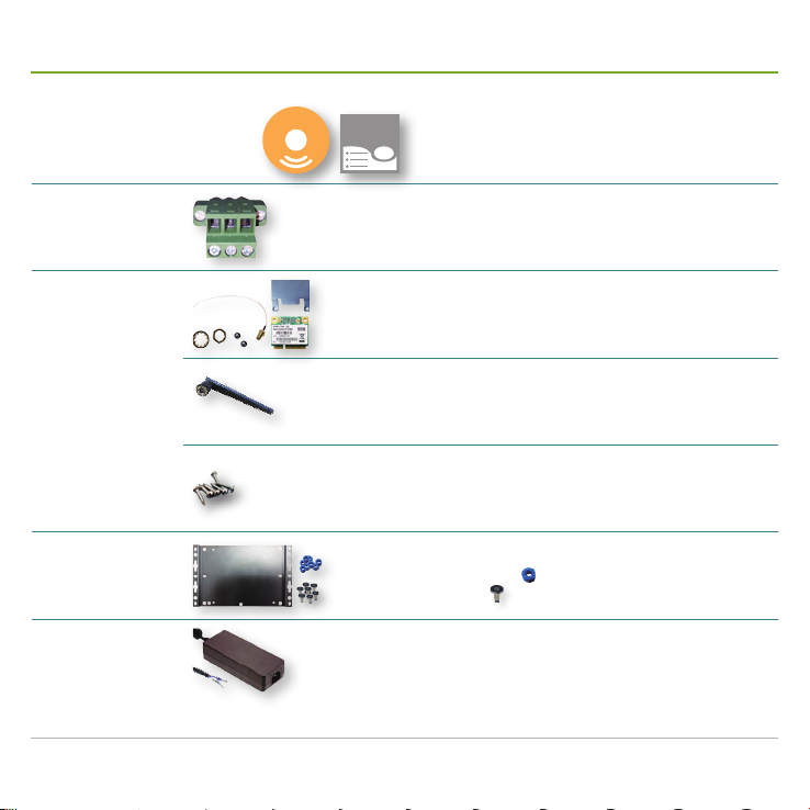
Accessories ................................................................. 2
Take a Tour .................................................................. 4
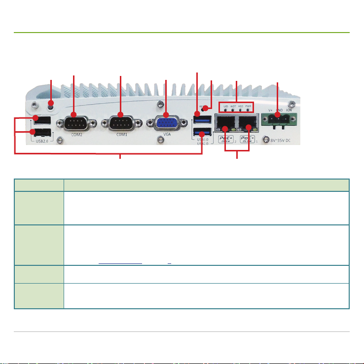
Front Panel........................................................................4
Rear Panel ........................................................................6
Side Panel .........................................................................7
Motherboard ................................................................ 8
Install Hardware..........................................................11
Open Cutout Door ........................................................... 11
Install SATA HDD/SSD ....................................................12
Install a WiFi Module .......................................................14
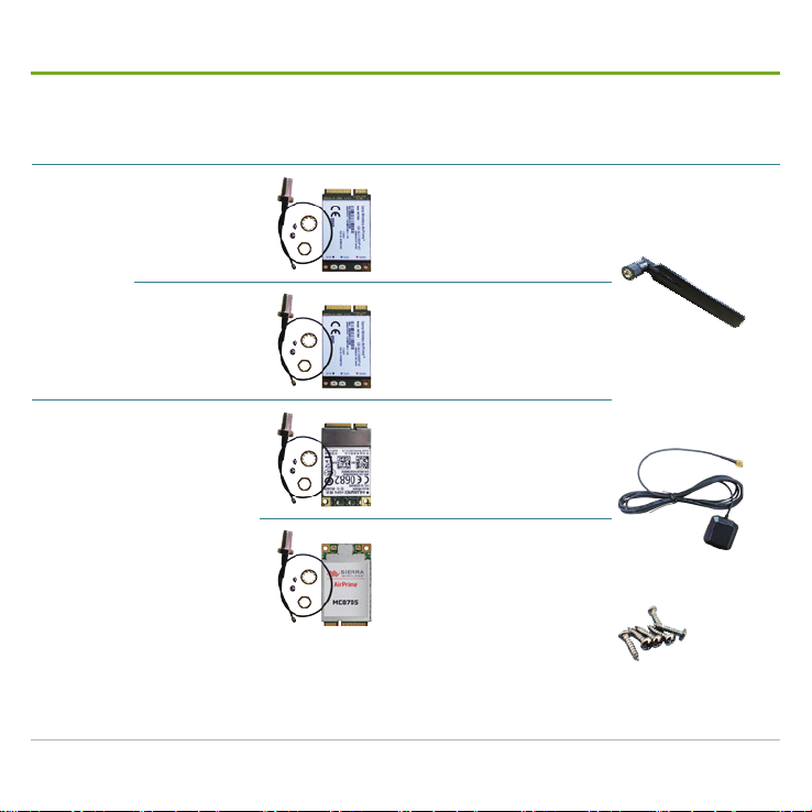
Install a 3G or 4G plus GPS Module (Optional) ..............17
Install a SIM Card............................................................20
Mount the Mobile NVR .............................................. 23
Wire DC-in Power Source ......................................... 25
Manage Ignition Power.............................................. 27
Wire Ignition Signal .........................................................27
Select Ignition Power Mode.............................................28
Set up Windows®...................................................... 29
Initialize HDDs........................................................... 30
Launch & Log in......................................................... 31
Use Installation Wizard.............................................. 32
Congure Network Parameters ................................. 39
Create Storage Volumes ........................................... 40
Auto-add a Camera ................................................... 41
Appendix. Install 3G/4G Device Driver & Connect Mobile
Network for the 1st Time............................................ 43
Appendix. Install WiFi Device Driver & Connect WiFi
Network for the 1st Time............................................ 46

Mobile NVR M1121 Quick Start Guide
ii
Preface
About this Document
This document is meant for the experienced users and integrators with hardware knowledge of personal
computers. If you are not sure about the description herein, consult your vendor before further handling.
We recommend that you keep one copy of this document for the quick reference for any necessary
maintenance in the future. Thank you for choosing GVD products.
Declaration of Conformity
FCC
This equipment has been tested and found to comply with the limits for a Class A digital device, pursuant
to part 15 of the FCC Rules. These limits are designed to provide reasonable protection against harmful
interference when the equipment is operated in a commercial environment. This equipment generates,
uses, and can radiate radio frequency energy and, if not installed and used in accordance with the
instruction manual, may cause harmful interference to radio communications. Operation of this equipment
in a residential area is likely to cause harmful interference in which case the user will be required to correct
the interference at his own expense.
CE
The product(s) described in this manual complies with all applicable European Union (CE) directives.
For computers systems to remain CE compliant, only CE-compliant parts may be used. Maintaining CE
compliance also requires proper cable and cabling techniques.
Copyright and Trademarks
This document contains proprietary information protected by copyright. All rights are reserved. No part
of this document may be reproduced by any mechanical, electronic, or other means in any form without
prior written permission of the manufacturer. Company/product names mentioned herein are used
for identification purposes only and are trademarks and/or registered trademarks of their respective
companies.

Mobile NVR M1121 Quick Start Guide iii
Hardware Requirements
Recording data is one of the most important parts for video surveillance, and hard disk drives are one of
the most important components to safely store the recording data.
It is always recommended that you use the hard disk drives certified by GVD. Find the list of the GVD-
certified hard disk drives at the link below:
http://www.gvdigital.com/gvdweb/html/document/Support_Lists/Certified%20HDD%20List.pdf
NOTE:
* GVD does not guarantee the system performance if a HDD model that is not certified by GVD is used.
* GVD recommends that you always use enterprise-level SATA hard drives for GVD enterprise NVR, Failover Server, Backup Server,
Extended Storage because it supports TLER (Time Limited Error Recovery), higher MTBF, higher Duty Cycles and typically include a
sensor for rotation and vibration.

Mobile NVR M1121 Quick Start Guide
iv

Mobile NVR M1121 Quick Start Guide 1
Introduction
Thank you for choosing GVD products. The M1121 is the light-weight
solution of GVD's brand new mobile NVR line, M1 Series. Powered by
Intel® Atom™ Bay Trail E3845 Quad-core, M1121 is a fanless NVR to
deliver appropriate CPU calculation with low power consumption. The
integrated Intel®HD Graphics that brings DirectX11 also allows the
NVRs to deliver superb video and audio.
The M1121 comes with rich data connection including 3G, 4G
and WiFi to stay constantly connected with the control center. The
intelligent power management prevents startup failure and allows
the control center to watch over the car battery usage through 3G,
4G or WiFi. Isolated DIO on the other hand keeps the mobile NVR connected with other in-vehicle devices
such as a car door sensor, and the change of DIO states can be sent to the control center.
If you opt for a GPS (plus 3G or 4G) module to go inside the mobile NVR, the control center can instantly
locate the vehicle that carries the mobile NVR on the map. Also on option is a G-sensor to measure the
vibration every couple of minutes and feed the data back to the control center. On the other hand the
mobile NVR is verified to be anti-shock and anti-vibration to guarantee more protection to the hard disk
drives onboard and ensures non-stop video recording.
Two PoE LAN ports are featured on the M1121. Each port
delivers power up to 25.5W and simultaneously transfers data
up to 1000 Mb/s over a single CAT-5e/CAT-6 cable. The highly
integrated mechanical design on the other hand allows the
M1121 to efficiently distribute the heat generated by the PoE
circuit and therefore makes the M1121 a very stable fanless
NVR with PoEs. The mechanical design is also modular to
make the NVR easy-to-install and maintain.
The simple and sturdy design makes the M1121 ideal for all
kinds of vehicles. It is your best choice for IP video surveillance
on the go.
Product Highlights
■Power over Ethernet
■Anti-shock / anti-vibration
■Rich data connections
■Intelligent power management
■Isolated DIO

Mobile NVR M1121 Quick Start Guide
2
Accessories
Driver CD & User's Manual
DRIVERS
User’s
Manual
Terminal Block
1 x 3-pin male terminal block for 8~35VDC output
WiFi Module Kit
SparkLAN WPER-172GN 802.11b/g/n USB Half Mini Card
■802.11b/g/n ISM Band: 2.400 ~ 2.4835GHz
■Antenna: 2 x U.FL connectors (diversity antenna), 1T1R
1 x External Antenna
■RP-SMA male body & female inner contact
A few screws to x the module
■stainless-steel round philips screws
Wall-mount Kit
■1 wall-mount bracket
■8 x rubber bumpers
■8 x M4 screws
Power Adapter
(Optional)
24V/6.67A 160W AC/DC adapter
(for +8~35VDC output)

Mobile NVR M1121 Quick Start Guide 3
Accessories
Region Module (w/ GPS capability) & Wire External Antenna
4G+GPS
Module Kit
(Optional)
Southeast Asia,
Middle East &
partly India (1800
MHz only)
Sierra Wireless® AirPrime™
MC7304 w/ 15cm internal wire
■LTE-FDD / HSPA+ (B1, B2, B3, B5,
B7, B8, B20)
1 x 3G or 4G External
Antenna
■RP-SMA male body &
male inner contact
1 x GPS External
Antenna
■Length: 300cm
■RP-SMA male body &
male inner contact
A few screws to x the
module
■Stainless-steel round
philips screws
North America &
Latin America
Sierra Wireless® AirPrime™
MC7354 w/ 15cm internal wire
■LTE-FDD, HSPA+, GSM/GPRS/
EDGE, GSM/GPRS/EDGE, CDMA
(B1, B2, B4, B5, B8, B13, B17, B25,
BC0, BC1, BC10)
3G+GPS
Module Kit
(Optional)
All regions
HUAWEI MU609 Mini-PCIe
■HSPA+/UMTS quad-band
850/900/1900/2100 MHz
■GSM/GPRS quad-band
850/900/1800/1900 MHz
Sierra Wireless® AirPrime™
MC8705 w/ 15cm internal wire
■Operational bands: WCDMA 850,
WCDMA 900, WCDMA 1900,
WCDMA 2100

Mobile NVR M1121 Quick Start Guide
4
Take a Tour
Front Panel
Power
button DB-15 video
connector
USB 3.0
port
PoE ports
DC-in
power
jack
USB 2.0
ports
Reset
button
Status
LEDs
COM2 COM1
Title Description
Power button
Turns on/off the system. Hit this button to turn on the system. Hit this button again to power off the
system. Press-and-hold this button to force system shutdown.
There must be no less than 5 seconds between each power on/off.
The PWR status LED lights green when the system is powered on.
COM1 & COM2
Two serial COM ports.
Both support RS232, RS422 and RS485, user-denable at the BIOS Setup utility.
Implemented with industrial-grade ITE8783 Super IO chip (-40 to 85°C) and up to 115200 bps data
transfer rate.
See also COM1 & COM2 on page 9 for the pin denition.
DB-15 video
connector Connector for an external VGA monitor or projector.
USB 3.0 port
One USB 3.0 port that runs with xHCI (eXtensible Host Control Interface) by default and supports the
devices of USB 3.0, USB 2.0, USB 1.1 and USB 1.0.
Legacy USB is only supported when the xHCI is set to Smart Auto in the BIOS Setup utility.

Mobile NVR M1121 Quick Start Guide 5
Take a Tour
Title Description
USB 2.0 ports
Three USB 2.0 ports that run with EHCI (Enhanced Host Control Interface) by default and supports the
devices of with USB 2.0, USB 1.1 and USB 1.0.
Legacy USB is supported, which means USB keyboard/mouse still work in DOS.
Reset button
Restarts the system without turning off the power.
To prevent false trigger, this button is recessed in the panel. Use an object with a pointed end to hit
this button.
Status LEDs
Deliver the states of some system parts:
Printed Text Color Description
PWR Green Lights when the system is powered on.
HDD Red Lights when the SATA HDD is being accessed.
WDT Amber Blinks when the watchdog timer is started.
UID Green Reserved.
PoE ports
Two Power-over-Ethernet LAN ports that feature the following:
Implemented with Intel®I210 GbE controller.
Status LEDs deliver the follow states:
LED Color State Description
LINK/ACT Yellow
Off Disconnected
On Connected with no data transmission
Blinking Connected with data transmission active
SPEED Green Off The data speed reaches 10Mbps.
On The data speed reaches 100Mbps.
Orange On The data speed reaches 1000Mbps.
DC-in power
jack
3-pin DC in power jack with ignition support.
A wide range of power input from +8 to +35 V including the prevalent 12V and 24V vehicle power
system.
See also DC-in Power Jack on page 9 for the pin denition.

Mobile NVR M1121 Quick Start Guide
6
Take a Tour
Rear Panel
DVI-D
connector
CAN
bus
port
Mic-in
Line-out COM4 COM3
Antenna
cutout
hole
Title Description
DVI-D video connector Connector for an external montior with DVI-D interface
Mic-in & line-out Microphone input (pink) and speaker out (green).
Implemented with Intel®High Denition Audio and Realtek®ALC262 codec.
COM3 & COM4
Two serial COM ports.
Both support RS232 only.
Implemented with industrial-grade ITE8783 Super IO chip (-40 to 85°C) and up to 115200
bps data transfer rate.
See also COM3 & COM4 on page 10 for the pin denition.
CAN bus port
Provides a DB-9 CAN bus port.
Supports CAN2.0A and CAN2.0B up to 1 Mbps.
See also CAN bus connector on page 10 for the pin denition.
Antenna cutout hole A cutout hole for an antenna-wired SMA connector to join an external antenna.

Mobile NVR M1121 Quick Start Guide 7
Take a Tour
Side Panel
SIM card
socket 2
Antenna
cutout holes
Title Description
SIM card socket
Outside-accessible SIM card socket.
The system provides two SIM card sockets
in total. The other one cannot be accessed
unless the cutout door at the bottom is
removed. See also Open Cutout Door on
page 11 for more details.
Antenna cutout holes
Two cutout holes.
Each cutout hole is for an antenna-wired
SMA connector to go through to join an
external antenna. See also Install a WiFi
Module on page 14 or Install a 3G or 4G
plus GPS Module (Optional) on page 17
more details.

Mobile NVR M1121 Quick Start Guide
8
Motherboard
1
2
3
4
5
0
6
7
8
9
USB-only
Mini PCIe
socket
SIM card
socket 2
DVI-D
video
connector SATA
signal
connector
3-pin
DC-in
power jack
DB-15
video
connector
USB 2.0
ports
Line-out
CAN bus
connector
DDR3L
SO-DIMM
socket
Mic-in
USB 3.0
ports
PoE
ports
SATA power
receptacle
Mini
PCIe
socket
Half-size
mSATA
connector
SIM
card
socket 1
Ignition
mode
switch
COM4 COM3
COM2COM1

Mobile NVR M1121 Quick Start Guide 9
Motherboard
The table below shows the function of some
connectors on the boards, sorted as previously
labelled in Motherboard.
Title Function
COM1 & COM2
Serial COM ports that support
RS232, RS422 and RS485
See the pin denition in COM1
& COM2 on page 9.
COM3 & COM4
Serial COM ports that support
RS232 only.
See the pin denition in COM3
& COM4 on page 10.
3-pin DC-in
power jack
Power connector with ignition
control accepting wide-range DC
power in from 8V to 35V.
See the pin denition in DC-in
Power Jack on page 9.
CAN bus
connector
CAN bus port supporting CAN2.0A
and CAN2.0B up to 1Mbps.
See the pin denition in CAN
bus connector on page 10.
COM1 & COM2
5
1
6
9
Desc.: Serial COM ports that support RS232, RS422 and
RS485
Connector: Male D-SUB9 connector
Pinout: Pin RS232 RS422 RS485
1DCD
2RX 422 TXD+ 485 TXD+/RXD+
3TX 422 RXD+
4DTR 422 RXD-
5GND GND GND
6DSR
7RTS
8CTS 422 TXD- 485 TXD-/RXD-
9RI
DC-in Power Jack
1
Desc.: Power connector with ignition control accepting wide-
range DC power in from 8V to 35V.
Connector: 3-pin terminal block
Pinout: Pin Def. Description
1V+ Positive polarity of DC power input
from 8V~35V.
2GND Negative polarity of DC power input
3IGN Ignition input for ignition power control

Mobile NVR M1121 Quick Start Guide
10
Motherboard
COM3 & COM4
5
1
6
9
Desc.: Serial COM ports that support RS232 only
Connector: Male D-SUB9 connector
Pinout: Pin Def. Pin Def.
1DCD 6DSR
2RX 7RTS
3TX 8CTS
4DTR 9RI
5GND
CAN bus connector
5
1
6
9
Desc.: CAN bus port supporting CAN2.0A and CAN2.0B up to
1Mbps.
Conn.: Male D-SUB9 connector
Pinout: Pin Def. I/O Desc.
1Reserved No Reserved pin. Keeps unconnected.
2Reserved No Reserved pin. Keeps unconnected.
3CAN_H Yes CAN bus high-level voltage
4Reserved No Reserved pin. Unconnected.
5CAN_L Yes CAN bus low-level voltage
6Reserved No Reserved pin. Keeps unconnected.
7Reserved No Reserved pin. Keeps unconnected.
8Reserved No Reserved pin. Keeps unconnected.
9Reserved No Reserved pin. Keeps unconnected.

Mobile NVR M1121 Quick Start Guide 11
Open Cutout Door
To facilitate your hardware installation and maintenance, the mobile NVR has a cutout on its
bottom. Follow the guide below to open the cutout door.
1. Place the mobile NVR upside down on a at and soft surface. Then loosen and remove
the three screws that x the cutout door at the bottom cover.
Here is a cutout
to access the
inside of the
mobile NVR.
2. Part the cutout door from the mobile NVR.
The inside of the mobile NVR then comes to view.
Part the cutout door from the mobile NVR.

Mobile NVR M1121 Quick Start Guide
12
Install SATA HDD/SSD
Follow the guide below to install a SATA HDD/SSD to the mobile NVR:
1. Open the cutout door as described in Open Cutout Door on page 11.
The inside (motherboard) of the mobile NVR then comes to view.
Open the cutout door at the bottom.
2. Install a SATA HDD or SSD onto the cutout
door by fastening 4 screws.
3. Pull the SATA cable connector from the
motherboard.
Find the SATA
cable connector on
the motherboard.

Mobile NVR M1121 Quick Start Guide 13
Install SATA HDD/SSD
4. Connect the SATA HDD/SSD.
Connect the SATA
HDD/SSD with
the onboard SATA
cable.
5. Restore the cutout door.
Restore the
cutout door by
fastening the 3
screws.

Mobile NVR M1121 Quick Start Guide
14
Install a WiFi Module
The mobile NVR comes with two PCI Express Mini Card sockets to carry a wireless module for data
connection or GPS receiver. Follow the guide below to install a WiFi module to the mobile NVR:
1. Open the mobile NVR and access the motherboard as
described in Open Cutout Door on page 11.
The motherboard then comes to view.
2. Find the two PCIe Mini Card sockets on the motherboard.
The connector has a break
among the contact pins.
Connector’s break
Mini-Card socket
socket for a
wireless module
with outside-
accessible SIM
card support
socket for a
wireless module
with an internal
SIM card holder
3. Have the
WiFi module
from the
accessories.
The module
is a half-size
module of PCIe Mini Card,
with two U.FL connectors.
4. In order to make the half-
size WiFi module compatible
with the Mini Card socket,
extend the WiFi module with
a “mini half bracket”. Join
them together by using two
screws.
Two U.FL connectors
5. Plug the Wi-Fi module to
the socket’s connector by
a slanted angle. Fully plug
the module, and note the
notch on the wireless module
should meet the break of the
connector.
Table of contents
Other GVD Network Hardware manuals