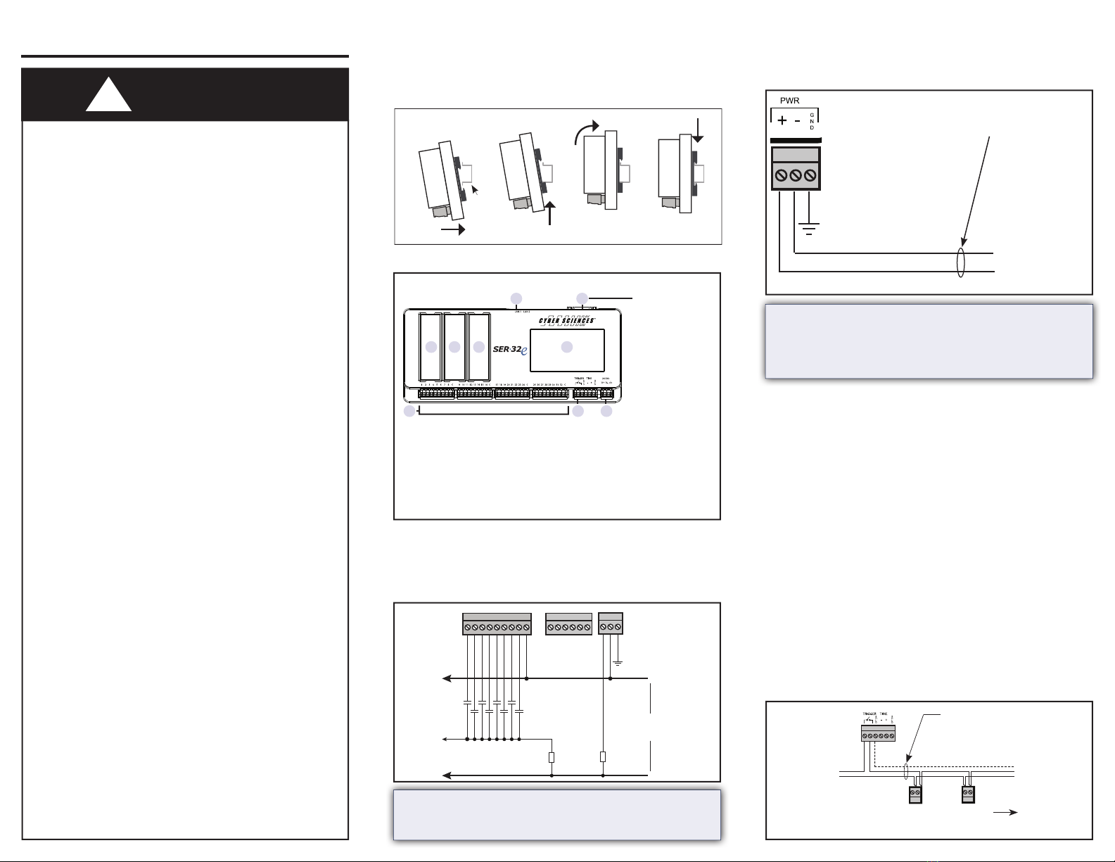
The CyTime SER-32e is mounted to a standard DIN rail
by engaging the bottom edge of the rail rst, pressing
up and rotating the unit into place.
Quick Start Guide
DIN
rail
Control Power
Wiring
Inputs
The SER requires a nominal 24 VDC, 7 VA control power
source.
Ground
(green-wire ground)
#18 AWG (minimum)
cable
–
+ 24 Vdc
#18 to #12 AWG
Note: 18 AWG (Belden 8760) shielded twisted pair cable is
recommended for all input and output connections.
Note: The common connection from the 24Vdc power supply
should not be connected to green-wire ground unless speci-
ed by local electrical codes.
The SER can be congured to receive legacy time pro-
tocols (IRIG-B or DCF77) using option wiring accessories
(EZC-IRIG-B or EZC-DCF77). For additional information,
see the SER-32e User Guide and EZC instruction bulletin.
When the master time source is PTP or NTP, the SER can
be congured to output legacy time protocols (IRIG-B,
DCF77, 1 per 10) using optional wiring accessories
(PLX-5V or PLX-24V). For additional information, see the
SER-32e User Guide and the PLX Instruction Bulletin.
The SER has 32 isolated digital inputs arranged in 4
groups of 8 inputs, each sharing a common return. A 24
VDC whetting source is required.
Time Sync OUT (IRIG-B, DCF77 or 1 per 10)
Trigger Output
The Trigger output can be used to initiate action in
other devices such as a waveform capture, annunciation
or control.
Time Sync IN (IRIG-B or DCF77)
HAZARD OF ELECTRIC SHOCK, EXPLOSION, OR
ARC FLASH
●Only qualied workers should install this
equipment. Such work should be performed
only after reading this entire set of instructions.
●NEVER work alone.
●Before performing visual inspections, tests, or
maintenance on this equipment, disconnect
all sources of electric power. Assume that all
circuits are live until they have been completely
de-energized, tested, and tagged. Pay particular
attention to the design of the power system.
Consider all sources of power, including the
possibility of backfeeding.
●Apply appropriate personal protective equip-
ment (PPE) and follow safe electrical practices.
For example, in the USA, see NFPA 70E.
●Turn o all power supplying the equipment
in which the device is to be installed before
installing and wiring the device.
●Always use a properly rated voltage sensing
device to conrm that power is o.
●Beware of potential hazards, wear personal
protective equipment, and carefully inspect
the work area for tools and objects that may
have been left inside the equipment.
●The successful operation of this equipment
depends upon proper handling, installation,
and operation. Neglecting fundamental
installation requirements may lead to
personal injury as well as damage to
electrical equipment or other property.
Failure to follow these instructions can
result in death or serious injury.
DANGER
!
25 26 27 28 29 30 31 32 C +-G
+
–
Fuse, 1A
(optional)
Fuse, 1A
(optional)
Monitored
Contacts
(typical for 32
Inputs) 24 Vdc
Control
Power
* Note: this shield connection is provided simply
as a convenient means for terminating the
cable shield; it is not connected internally within
the CyTime SER.
A B shield*
to additional
devices
Belden 8760 cable, or
equivalent
Digital input of power meter or other
compatible device
+
–
shield (optional)
24 Vdc
(100 mA max)
IRIG-B or DCF77 IN
(via EZC)
IRIG-B, DCF77 or
1per10 OUT (via PLX)
OR
1 2
3 4 5 6
7 8 9
1. Ethernet 6. Touchscreen
2. Time Sync IN or OUT 7. Inputs (32)
3. Expansion Module 8. Trigger OUT /
4. Expansion Module RS-485
5. Power Control Module 9. Control Power


