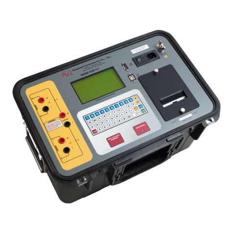
doble M4000 series User manual

Doble Engineering Company
85 Walnut Street
Watertown, Massachusetts 02472-4037
(USA)
PN 500-0110 72A-1230 Rev. F
July 22, 2005
M4000 Insulation Analyzer
User Guide

Copyright
©
2000
By Doble Engineering Company
All Rights Reserved.
This Manual is the sole property of the Doble Engineering Company (Doble)
and is provided for the exclusive use of Doble Clients under contractual
agreement for Doble Test Equipment and Services.
In no event does the Doble Engineering Company assume the liability for any
technical or editorial errors of commission, or omission; nor is Doble liable for
direct, indirect, incidental, or consequential damages arising out of the use or
inability to use this Manual.
Government Restricted Rights Legend: Use, duplication, or disclosure by the
U.S. Government is subject to restrictions as set forth in subparagraphs (c)(1)
and (c)(2) of the Commercial Computer Software - Restricted Rights Clause at
FAR 52.227-19.
This manual is protected by copyright, all rights reserved, and no part hereof
may be photocopied or reproduced in any form without prior written consent
of the Doble Engineering Company.
Copyright
©
2000
By Doble Engineering Company
All Rights Reserved.

72A-1230 Rev. F i
July 22, 2005
Preface
Structure of this Manual
This manual consists of 4 chapters and 4 appendices.
Chapter 1 “Introduction” introduces the functions and
architecture of the M4000 Insulation Analyzer, as well
as important safety considerations for its use.
Chapter 2 “M4000 Software” provides an overview of M4000
software and its installation.
Chapter 3 “Running M4000 Tests” describes procedures for
executing specimen tests.
Chapter 4 “M4100 Instrument Troubleshooting” provides initial
steps in troubleshooting problems and isolating a
problem to either the M4100 or M4200c.
Appendix A “M4000 Components Lists” describes accessories
included with the M4000 Insulation Analyzer.
Appendix B “Warranty” provides Doble warranty provisions
applicable to the M4000.
Appendix C “Error Messages” lists error message numbers and
descriptions.
Appendix D “Part Numbers” lists the M4000 Insulation Analyzer
part numbers.

ii 72A-1230 Rev. F
July 22, 2005
Conventions Used in this Manual
The following terms and typographical conventions are used in the manual:
Convention Description
Windows Refers to the Microsoft Windows operating system,
Version 98 or later.
Click Quickly press and release the left mouse button.
Double-click Quickly press and release the left mouse button twice
without moving the mouse.
Select Position the cursor on the desired option and click the
left mouse button once. Or, highlight the desired
option using the arrow keys and press ENTER. Or, press
ALT and the underlined letter.
Press Type a single keyboard key. For example, press ENTER.
FN+(appropriate key) Press and hold the FN key, and press (appropriate
key).
Bold Courier Text Indicates characters to be typed.

M4000 Insulation Analyzer User Guide
72A-1230 Rev. F 1
July 22, 2005
1. Introduction
Measurement Principles ..................................................................................................................... 1-1
Safety .................................................................................................................................................. 1-1
M4000 Components ........................................................................................................................... 1-2
M4100 Instrument ........................................................................................................................ 1-2
M4200c Controller ....................................................................................................................... 1-5
Third-Party Controller.................................................................................................................. 1-7
M4000 Software........................................................................................................................... 1-7
Optional M4150 And M4151 Field Calibration References........................................................ 1-7
Doble Standard Turns Ratio Capacitor ........................................................................................ 1-8
External Reference ....................................................................................................................... 1-8
M4300 Transport.......................................................................................................................... 1-8
Doble Test Assistant (DTA) Software ......................................................................................... 1-9
M4110 Leakage Reactance Interface ........................................................................................... 1-9
Operating with the M4300 Transport ............................................................................................... 1-10
Storage and Moving Mode.........................................................................................................1-10
Testing Mode.............................................................................................................................. 1-13
When Finished Testing............................................................................................................... 1-15
M4000 PC Cable ........................................................................................................................ 1-16
Transport, Storage and Shipping ...................................................................................................... 1-17
Transporting and Storing the M4000 ......................................................................................... 1-17
Shipping Instructions.................................................................................................................. 1-18
Safety Considerations....................................................................................................................... 1-19
Definitions.................................................................................................................................. 1-19
Safety Practices – General Rules ............................................................................................... 1-20
Clearances .................................................................................................................................. 1-20
Grounding................................................................................................................................... 1-21
Personnel Safety......................................................................................................................... 1-21
M4000 Connections ................................................................................................................... 1-22
M4000 Operation ....................................................................................................................... 1-23
M4000 Safety Features............................................................................................................... 1-23
Safety Precautions ...................................................................................................................... 1-25
Safety Precautions for Various Types of Apparatus .................................................................. 1-26
Safety Summary ......................................................................................................................... 1-28

272A-1230 Rev. F
July 22, 2005
2. M4000 Software
Upgrading or Installing M4000 Software........................................................................................... 2-1
Software Installation ........................................................................................................................... 2-1
M4000 Software ........................................................................................................................... 2-1
Doble Test Assistant (DTA) Software (Optional)........................................................................ 2-5
Optimization ....................................................................................................................................... 2-5
COM port Setting ......................................................................................................................... 2-5
Mouse Settings ............................................................................................................................. 2-5
Time/Date Format......................................................................................................................... 2-6
Introduction to M4000 Software......................................................................................................... 2-6
What’s New .................................................................................................................................. 2-6
The M4000 Program..................................................................................................................... 2-7
Icons.............................................................................................................................................. 2-7
Menu Bar ...................................................................................................................................... 2-8
Clipboard Test Mode .......................................................................................................................... 2-9
Menu Items ....................................................................................................................................... 2-11
Mode Menu................................................................................................................................. 2-11
Test Menu ................................................................................................................................... 2-11
Diagnostics ................................................................................................................................. 2-12
View Menu ................................................................................................................................. 2-12
Tools Menu................................................................................................................................. 2-12
Temperature Correction.................................................................................................................... 2-12
Configuration .................................................................................................................................... 2-13
System Configuration ................................................................................................................. 2-13
Clipboard Configuration............................................................................................................. 2-14
DTA Field Configuration ........................................................................................................... 2-16
Instrument Configuration ........................................................................................................... 2-18
Advanced Configuration............................................................................................................. 2-19
Using Help ........................................................................................................................................ 2-21
Contents...................................................................................................................................... 2-21
About M4000 For Windows....................................................................................................... 2-22
Printer Setup ..................................................................................................................................... 2-22
Printing.............................................................................................................................................. 2-22
3. Running M4000 Tests

M4000 Insulation Analyzer User Guide
72A-1230 Rev. F 3
July 22, 2005
Entering Clipboard Information ......................................................................................................... 3-1
Nameplate Information ................................................................................................................ 3-1
Administrative Information.......................................................................................................... 3-2
Test Conditions ............................................................................................................................ 3-3
Test Results Information .................................................................................................................... 3-4
Running Single and Multiple Clipboard Tests ................................................................................... 3-6
Raising Test Voltage .................................................................................................................... 3-7
Test Results .................................................................................................................................. 3-8
Clearing Test Results ................................................................................................................. 3-10
Saving Test Results .................................................................................................................... 3-11
Graphing Test Results ................................................................................................................ 3-11
External Reference/Source Test (Optional Software) ...................................................................... 3-12
Running A UST Test.................................................................................................................. 3-12
Running a GST-Guard Test........................................................................................................3-14
Leakage Reactance Test (Optional Software) .................................................................................. 3-16
DTA Mode........................................................................................................................................ 3-17
DTA Tests......................................................................................................................................... 3-17
DTA Data Manager .......................................................................................................................... 3-18
Preparing for a DTA Test ................................................................................................................. 3-19
Starting a DTA Test.......................................................................................................................... 3-19
DTA Icons and Function Keys ......................................................................................................... 3-24
Using A Resonator............................................................................................................................ 3-25
Operating Procedure of Type C Resonating Inductor................................................................ 3-26
General Description of Type C-1 Coupler - RIV Test Procedure .................................................... 3-28
4. M4100 Instrument Troubleshooting
Assigning A Trouble To The M4100 Instrument (Or The M4200c Controller)................................ 4-1
Quick Checks ............................................................................................................................... 4-1
Troubleshooting Resources .......................................................................................................... 4-2
Isolating Trouble .......................................................................................................................... 4-3
Avoiding Problems....................................................................................................................... 4-4
Detailed Troubleshooting Of The M4100 Instrument........................................................................ 4-5
Overview of M4100............................................................................................................................ 4-7
Overview of Individual Replaceable Components............................................................................. 4-9
Troubleshooting from Symptoms..................................................................................................... 4-12
Troubleshooting from Error Messages.............................................................................................4-16

472A-1230 Rev. F
July 22, 2005
Troubleshooting from Diagnostics ................................................................................................... 4-21
Running Diagnostics................................................................................................................... 4-21
System Status.............................................................................................................................. 4-23
Calibration Verification.............................................................................................................. 4-26
Field Recalibration ..................................................................................................................... 4-31
Subsystem Diagnostics............................................................................................................... 4-34
M4100 Component List.............................................................................................................. 4-38
Thermal Profile........................................................................................................................... 4-39
Communications Loopback Test ................................................................................................ 4-40
Running Other Tests ......................................................................................................................... 4-42
Checking the High Voltage Test Cable ...................................................................................... 4-42
Checking the Low Voltage Test Leads....................................................................................... 4-42
Checking M4100 Guard-to-Ground Insulation .......................................................................... 4-43
Checking Instrument Accuracy in the Field ............................................................................... 4-43
Voltage Verification ................................................................................................................... 4-44
Accessing M4100 Components ........................................................................................................ 4-46
Removing the Front and Top Covers ......................................................................................... 4-46
Removing the Card Cage Cover................................................................................................. 4-48
M4100 Internal Checks..................................................................................................................... 4-50
Fan Operation ............................................................................................................................. 4-50
Low-Voltage Power Checkout ................................................................................................... 4-51
Guard-to-Ground Shorting Problems ......................................................................................... 4-51
LVPS Fuses ................................................................................................................................ 4-52
W8/W9/W11 Cable Checkout.................................................................................................... 4-53
Orange Cable Checkout.............................................................................................................. 4-54
Transformer Checks ................................................................................................................... 4-54
W46 Cable Checkout.................................................................................................................. 4-55

M4000 Insulation Analyzer User Guide
72A-1230 Rev. F 5
July 22, 2005
Replacing M4100 Components ....................................................................................................... 4-56
Returning Replaced Components............................................................................................... 4-57
Removing and Replacing the Front Panel Assembly................................................................. 4-58
Replacing the Guard Front Panel Board .................................................................................... 4-61
Replacing the Amplifier Assembly ............................................................................................ 4-63
Replacing the Guard Mode Switch Board.................................................................................. 4-66
Replacing the Timing Board ......................................................................................................4-68
Replacing the DSP/CPU Board.................................................................................................. 4-70
Replacing the Safety Board........................................................................................................ 4-72
Replacing the Main Reference Assembly .................................................................................. 4-74
Replacing the Guard Board ........................................................................................................ 4-76
Replacing the Low Voltage Power Supply Board ..................................................................... 4-78
Replacing the Heater/Temperature Controller Board ................................................................ 4-80
Replacing the Optional Field Calibration Reference ................................................................. 4-82
Replacing the I/O Protection Board ........................................................................................... 4-83
Replacing the Transformer......................................................................................................... 4-85
Replacing the HV Pothead ......................................................................................................... 4-91
Replacing the Fan Filter ............................................................................................................. 4-93
Replacing the Fan....................................................................................................................... 4-94
Appendix A. M4000 Components Lists
M4000 Insulation Analyzer................................................................................................................A-1
Accessory Bag ....................................................................................................................................A-2
Documentation Bag ............................................................................................................................A-4
Appendix B. Warranty
RENTAL EQUIPMENT ....................................................................................................................B-1
PURCHASED EQUIPMENT ............................................................................................................B-1
Limited Warranty .........................................................................................................................B-1
Software Limited Warranty..........................................................................................................B-2
Limitations of Remedies ..............................................................................................................B-2
For Equipment Maintenance, Contact:.........................................................................................B-3
Appendix C. Error Messages
M4100 Instrument Run Time Error Messages ...................................................................................C-1

672A-1230 Rev. F
July 22, 2005
M4000 Firmware/Application Errors ................................................................................................ C-2
M4000 Communications Errors......................................................................................................... C-3
Appendix D. Part Numbers

72A-1230 Rev. F 1-1
July 22, 2005
1. Introduction
The M4000 Insulation Analyzer is used to determine the insulation quality of
high-voltage power apparatus in the field. This portable test set incorporates
automated Doble Testing with high accuracy and sensitivity, over a wide range
of values, and with minimal susceptibility to electrostatic interference and
noise.
Measurement Principles
The M4000 generates a 0-12 kV test signal with an internal sine wave
generator, a 3 kVA power amplifier and a step-up isolation transformer. The
M4000 then measures the voltage and current of the specimen and a reference
impedance by periodically sampling instantaneous values with an A/D
converter. The M4000 then calculates and reports test results by converting the
sampled data into vector (magnitude and phase) quantities and applying
conventional ac circuit theory. All reported results – including power loss,
power factor and capacitance – are derived from the vector voltage and
current.
The M4000 rejects interference through the judicious application of shielding,
line-synchronized reversal, and line frequency modulation (FM). The first two
techniques are similar to those employed in the earlier Doble M2H product
line. The FM technique involves running tests at sinusoidal frequencies 5% (or
even 10%, if necessary) above and below the line frequency and averaging the
results. The choice is user configurable.
The inevitable interference current component is removed from the sampled
data set before test results are calculated using synchronous detection. This is
a mathematical process that separates out a single frequency component in a
given signal. It is analogous to a bandpass filter centered at the test frequency.
Synchronous detection is also useful for removing harmonic distortion and
random noise in the test signal itself.
Safety
The M4000 is designed to drive grounded and ungrounded specimens at lethal
voltages and high power levels. Conventional ground-fault and current-
limiting schemes cannot be used to protect the operator under these test
conditions. Therefore, the M4000 implements special safety techniques to
minimize risk to the equipment operator.

M4100 Instrument
1-2 72A-1230 Rev. F
July 22, 2005
Both an operator and safety supervisor must be present when specimens are
tested. Each person holds a safety switch that directly controls the output of
the power amplifier through redundant electromechanical relays. In addition,
the control processor can vote to disable the dc supply to the safety relay coils,
thereby disabling the amplifier output if certain conditions are not met.
NOTE For greater safety details, see ”Safety Practices – General Rules”
on page 1-20.
M4000 Components
The M4000 Insulation Analyzer consists of the following components:
• M4100 Instrument
• M4200c Controller or Third-Party Controller
• M4000 Software
The following auxiliary components are optional:
• M4150 or M4151 Field Calibration Reference
• M4300 Transport
• Leakage Reactance Test Software
• External Reference Test Software
•DTASoftware
• M4110 Leakage Reactance Interface
• M4120 External Reference Module
• Doble Standard Turns Ratio Capacitor
• Safety Strobe
• Temperature and Humidity Probe
M4100 Instrument
The M4100 instrument supplies test voltage and test current to insulation
specimens. The M4100 instrument also contains measuring circuits to
determine the condition of the insulation under test, as well as direct control
safety circuits to ensure electrical safety of personnel and test apparatus.
The M4100 instrument has a time base generator that may be synchronized
either with the power system supplying power to the test instrument, or with
an internal crystal oscillator. This choice allows the test operator to select one
of two modes of test operation, Line Sync Reversal or Line Frequency
Modulation. When Line Sync Reversal Mode is selected, the time base is
synchronized to the power source and the test will use the standard Doble

M4000 Insulation Analyzer User Guide
72A-1230 Rev. F 1-3
July 22, 2005
polarity reversal technique to reverse the effects of electrostatic interference.
Selecting the Line Frequency Modulation Mode of operation will synchronize
the time base generator to the crystal oscillator. Two tests will be run for each
programmed test sequence. The first test is run at a frequency of 57 Hz and the
second test is run at 63 Hz. The measured test results of each test are combined
and averaged to give a 60 Hz equivalent test result. When operating in the 50
Hz frequency, the same technique will apply. The first test will run at 47 Hz,
and the second test will run at 53 Hz. This mode of test eliminates electrostatic
interference from measurement, by avoiding measurement at power line
frequency. It is also possible to select ± 10% of power line frequency as well.
Safety circuits have been designed into the M4100 instrument to ensure safety
of personnel. High voltage will not be supplied by the instrument if either of
the following circuits and conditions are not satisfied:
• The ground safety circuit verifies that the #6 bare copper safety
ground, which is attached from the instrument to the apparatus earth
ground, is at the same potential as the power supply ground.
• Two safety switches must be attached to the M4100 instrument front
panel and in the closed or depressed position prior to testing. One
switch is held by the M4000 Insulation Analyzer operator and the
second switch is held by a safety supervisor. The M4100 can be
configured to require both switches to be opened between test
sequences for the M4000 Insulation Analyzer to operate. Release of
one or both switches will terminate the test sequence and high voltage
potential.
A safety strobe light can be used in conjunction with the instrument and is
plugged into the front panel of the M4100. Whenever high voltage potential is
applied from the M4100, the safety strobe light will be energized and flashing.
Safety strobe connection will be required in order to operate the M4000
Insulation Analyzer, unless the default system configuration has been
modified to allow for the absence of a safety strobe. In this case, the strobe
connector can be removed from the M4100 front panel.

M4100 Instrument
1-4 72A-1230 Rev. F
July 22, 2005
Figure 1.1 Safety Strobe
Two optional items found on the M4100 front panel are the M4151 Field
Calibration Reference, which will be discussed below, and a Temperature and
Relative Humidity sensor. The Temperature and Relative Humidity Sensor
will process temperature and humidity readings at the time of test.
Front Panel
Figure 1.2 M4100 Instrument

M4000 Insulation Analyzer User Guide
72A-1230 Rev. F 1-5
July 22, 2005
M4200c Controller
Figure 1.3 M4200c Controller
• The M4200c Controller is the interface between the operator and the
M4000 Insulation Analyzer. The color display, control, data storage,
printing and communication functions are all provided by the M4200c
Controller. This component is covered in detail in a separate manual.
• The M4200c has been specifically designed and built to operate in
outdoor substations and other environments hostile to electronic test
equipment. The unit has been hardened to electrostatic discharge
(ESD) and radio frequency interference (RFI) to reduce or eliminate
their effects on internal electronic circuits.
• The outer case of the M4200c is made of ABS plastic over an
aluminum chassis that makes it rugged and suitable for transporting to
remote sites.
• The display is a six-inch by eight-inch color transflective liquid crystal
display (LCD) that runs in the VGA mode. The display has high
contrast in bright sunlight, and has backlight control for low ambient
light conditions. An LCD heater is installed to allow for use in cold
weather. An external monitor may be used in place of the LCD screen.
Access to the external display connector is found behind the access
door on the left side of the M4200c Controller.

M4200c Controller
1-6 72A-1230 Rev. F
July 22, 2005
• The keyboard is a standard notebook-type keyboard with a flexible
skin around the keys to prevent dirt and moisture from contaminating
the internal electronics and causing failure of the keyboard. An
external keyboard may be used in place of this keyboard. Access to the
external keyboard connector is to the right of the video connector
behind the access door on the left hand side of the M4200c Controller.
Figure 1.4 M4200c Controller External Connections
• The M4200c has a pointer device installed below the keyboard on the
front panel to allow for the use of mouse control of the display cursor.
A port on the left-hand side of the M4200c allows for the use of an
external, serial mouse.
• The M4200c has a built-in 200 dot per inch (dpi) graphic printer/
plotter. Paper for the printer/plotter is an uncoated thermal FAX paper
provided by Doble.
• The M4200c is equipped with an internal FAX/Modem board that may
be used to transfer data when used with the optional Doble Test
Assistant (DTA) program.
• The M4200c has a built in ethernet connection.
LAN Ext. Mouse Ext. Monitor Modem Ext. Keyboard
USB

M4000 Insulation Analyzer User Guide
72A-1230 Rev. F 1-7
July 22, 2005
• The M4200c has a built in USB port.
• Data may be stored on an internal hard drive or on a 3 1/2 - inch floppy
disk via the floppy disk drive located in the front of the controller.
Third-Party Controller
Certain PC’s using a Windows-based operating system available from other
suppliers can be used as a system controller in lieu of the M4200c controller.
These alternative machines can be used to control M4000 operations.
M4000 Software
Software provided with the M4200c or available to be loaded onto a Third-
Party Controller includes a program to run the M4000 Insulation Analyzer,
and if desired, the optional Leakage Reactance Test, External Reference Test,
and Doble Test Assistant (DTA) programs. For more information, refer to
Chapter 2.
Optional M4150 And M4151 Field Calibration References
The purpose of the M4150 and M4151 Field Calibration References are to
provide a means of obtaining System Status, Calibration Verification, and
Field Recalibration Tests of the M4100 instrument in the field. (For an
explanation of these tests, refer to ”Running Diagnostics” on page 4-21). The
Field Calibration Reference is mounted in the front panel of the M4100
instrument.
Figure 1.5 M4151 Field Calibration Reference

Doble Standard Turns Ratio Capacitor
1-8 72A-1230 Rev. F
July 22, 2005
Doble Standard Turns Ratio Capacitor
This is an optional small portable capacitor that can be energized at 10 kV for
performing turns ratio tests at high voltages with the M4000.
Figure 1.6 Doble Turns Ratio Capacitor
External Reference
This is an optional feature allowing the tester to test apparatus at their full
operating voltage using the M4000, providing a suitable external power source
and reference are provided by the user.
M4300 Transport
The M4300 Transport is an option for the M4000 Insulation Analyzer that
provides a means to move and store the M4000 system. It is also a platform for
the field, from which the M4000 can be easily used and operated. Refer to
”Storage and Moving Mode” on page 1-10 and ”Testing Mode” on page 1-13.
If a PC is to be substituted for the Controller, a support panel to be mounted on
the Controller support frame can be supplied.

M4000 Insulation Analyzer User Guide
72A-1230 Rev. F 1-9
July 22, 2005
Figure 1.7 M4300 Transport
Doble Test Assistant (DTA) Software
Optional Doble Test Assistant®(DTA) software provides standardized
apparatus test procedures and templates, data management, and optional
expert system software for insulation condition assessment. See Chapters 2
and 3 for further details.
M4110 Leakage Reactance Interface
This optional interface contains the circuitry necessary to convert the voltage
and current, measured during a Leakage Reactance test on a transformer, into
a form that can be measured by the M4100 Instrument. It also contains a
variac so that the proper test voltage can be obtained. The Leakage Reactance
test cannot be made without either this Interface or the M4130 Leakage
Reactance Module, and the accompanying software.

Storage and Moving Mode
1-10 72A-1230 Rev. F
July 22, 2005
When using this interface, the standard M4000 safety switch and safety strobe
are used. The necessary current and voltage cables are provided for connection
to the transformer, along with the necessary software, so that this becomes a
self-contained kit for this test. The user is only limited by the size of the variac
provided.
Figure 1.8 M4110 Leakage Reactance Interface
Operating with the M4300 Transport
The M4000 Insulation Analyzer is designed to be assembled on the M4300
Transport for storage, moving, and testing. When the M4000 is used with the
M4300 Transport, it can be set up in the following modes:
• Storage and Moving Mode
• Testing Mode
Storage and Moving Mode
The storage and moving mode will allow the user to transport and store the
M4000 Insulation Analyzer. The M4300 Transport is designed so that all the
components of the M4000 fit in a single, packaged unit (Figure 1.9).
This manual suits for next models
5
Table of contents
Other doble Measuring Instrument manuals
Popular Measuring Instrument manuals by other brands

enviromental express
enviromental express oakton PD250 instruction manual

Haehne
Haehne DMA2 Technical information and operating instructions

EUTECH INSTRUMENTS
EUTECH INSTRUMENTS FRETN100 Manuel d'instructions

ADTEK
ADTEK CPM-21 Operation manual

MSA
MSA ICM 2000 Plus Operation instructions

CoaguSense
CoaguSense Coag-Sense Prothrombin Time PT/INR Self-Test User's Manual