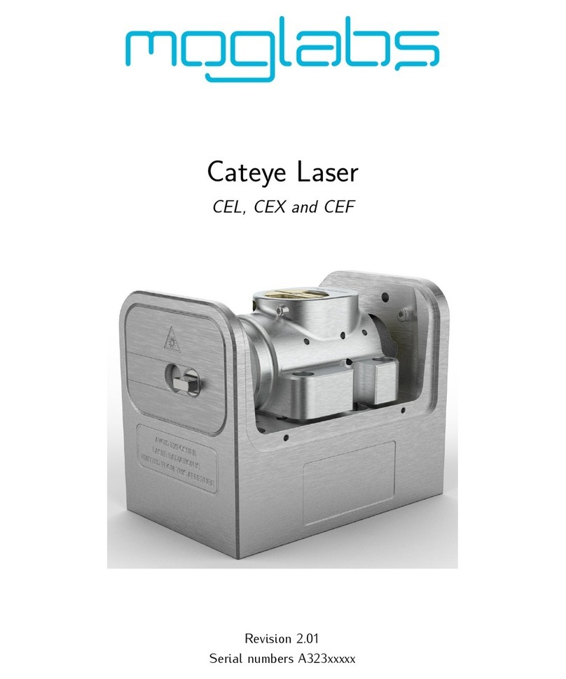
MOGlabs CEL User manual

External Cavity Diode Laser
CEL, CEX and CEF Cateye
Revision1.21

Limitation of Liability
MOGLaboratoriesPtyLtd(MOGLabs)doesnotassumeanyliabilityaris-
ingoutoftheuseoftheinformationcontainedwithinthismanual. This
documentmaycontainorreferenceinformationandproductsprotectedby
copyrightsorpatentsanddoesnotconveyanylicenseunderthepatent
rightsofMOGLabs,northerightsofothers. MOGLabswillnotbeliable
foranydefectinhardwareorsoftwareorlossorinadequacyofdataof
anykind,orforanydirect,indirect,incidental,orconsequentialdamages
inconnectionswithorarisingoutoftheperformanceoruseofanyofits
products. Theforegoinglimitationofliabilityshallbeequallyapplicable
toanyserviceprovidedbyMOGLabs.
Copyright
Copyright©MOGLaboratoriesPtyLtd(MOGLabs)2014–2022. No
partofthispublicationmaybereproduced,storedinaretrievalsystem,
ortransmitted,inanyformorbyanymeans,electronic,mechanical,pho-
tocopyingorotherwise,withoutthepriorwrittenpermissionofMOGLabs.
Contact
Forfurtherinformation,pleasecontact:
MOGLaboratoriesP/L
49UniversitySt
CarltonVIC3053
AUSTRALIA
+61399390677
MOGLabsUSALLC
41914thSt
HuntingdonPA16652
USA
+18142514363
www.moglabs.com

Preface
Diodelaserscanbewonderfulthings:theyareefficient,compact,lowcost,
highpower,lownoise,tunable,andcoveralargerangeofwavelengths.
Theycanalsobeobstreperous,sensitive,andtemperamental,particularly
externalcavitydiodelasers(ECDLs). Incombinationwithadvancedelec-
tronicssuchastheMOGLabsDLCexternalcavitydiodelasercontroller,the
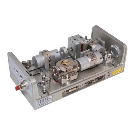
CEL “cateye”laserdescribedhereprovidesarobust,stable,acoustically
inert,lowlinewidthandhighlytunablelasersystem.
WehopethattheMOGLabsCELworkswellforyourapplication. Please
letusknowifyouhaveanysuggestionsforimprovementinthelaserorin
thisdocument,sothatwecanmakelifeinthelaserlabeasierforall,and
checkourwebsitefromtimetotimeforupdatedinformation.
MOGLabs,Melbourne,Australia
www.moglabs.com
i

ii

Safety Precautions
Safeandeffectiveuseofthisproductisveryimportant. Pleasereadthe
followinglasersafetyinformationbeforeattemptingtooperatethelaser.
Alsopleasenoteseveralspecificandunusualcautionarynotesbeforeusing
MOGLabslasers,inadditiontothesafetyprecautionsthatarestandard
foranyelectronicequipmentorforlaser-relatedinstrumentation.
CAUTION–USEOFCONTROLSORADJUSTMENTSOR
PERFORMANCEOFPROCEDURESOTHERTHANTHOSE
SPECIFIEDHEREINMAYRESULTINHAZARDOUSRADIATION
EXPOSURE
Laser output from the CEL can be dangerous. Please ensure that you
implementtheappropriatehazardminimisationsforyourenvironment,such
aslasersafetygoggles,beamblocks,anddoorinterlocks.MOGLabstakes
noresponsibilityforsafeconfigurationanduseofthelaser.Please:
•Avoiddirectexposuretothebeam.
•Avoidlookingdirectlyintothebeam.
•Notethesafetylabels(examplesshowninfigurebelow)andheed
theirwarnings.
•Whenthelaserisswitchedon,therewillbeashortdelayoftwosec-
ondsbeforetheemissionoflaserradiation,mandatedbyEuropean
lasersafetyregulations(IEC60825-1).
•TheSTANDBY/RUNkeyswitchmustbeturnedtoRUNbeforethelaser
can be switched on. The laser will not operate if the keyswitch
isintheSTANDBY position. Thekeycannotberemovedfromthe
controllerwhenitisintheclockwise(RUN)position.
iii

iv •Tocompletelyshutoffpowertotheunit,turnthekeyswitchanti-
clockwise(STANDBYposition),switchthemainspowerswitchatrear
ofunittoOFF,andunplugtheunit.
•WhentheSTANDBY/RUNkeyswitchisonSTANDBY,therecannotbe
powertothelaserdiode,butpowerisstillbeingsuppliedtothe
laserheadfortemperaturecontrol.
WARNING Theinternalcircuitboardandpiezoelectrictransducersareathigh
voltage during operation. The unit should not be operated with
coversremoved.
CAUTION AlthoughtheCEL isdesignedandpricedwiththeexpectationthat
theend-usercanreplacethediodeandchangethealignment,some
componentsarefragile. Inparticularthefilter,piezoactuator,and
outputcouplerareveryeasilydamaged. Pleasetakecareofthese
itemswhenworkinginsidethelaser.
Thefilterandoutputcouplerarehard-coatedandcanbecleaned
butgreatcareisneededaswithanyintracavitylaseroptics.
NOTE MOGLabsproductsaredesignedforuseinscientificresearchlabora-
tories.Theyshouldnotbeusedforconsumerormedicalapplications.
Label identification
TheInternationalElectrotechnicalCommissionlasersafetystandardIEC
60825-1:2007mandateswarninglabelsthatprovideinformationonthe
wavelength and power of emitted laser radiation, and which show the
aperturewherelaserradiationisemitted. Figure1showsexamplesof
theselabels,andfigures2and3showtheirlocationontheCELlaserand
large-chassisCEFversion.

v
AVOID EXPOSURE
LASER RADIATION IS
EMITTED FROM THIS APERTURE Aperture label engraving
Warning and advisory label
Class 3B
US FDA compliance
Model number: CEL
Serial number: A31907001
Manufactured: JULY 2019
Complieswith21 CFR1040.10,and1040.11 exceptfor
deviations pursuant to Laser NoticeNo.50, dated24 June2007
MOG Laboratories Pty Ltd, 49 University St
Carlton VIC 3053, AUSTRALIA
IEC 60825-1:2007
AS/NZS 2211.5:2006
INVISIBLE LASER RADIATION
AVOID EXPOSURE TO BEAM
CLASS 3B LASER PRODUCT
Wavelength
750 – 790 nm
Max Power
200 mW
Figure 1: WarningadvisoryandUSFDAcompliancelabels.

vi
Model number:
CEL
Serial number:
A31907001
Manufactured:
JULY 2019
Complieswith21 CFR 1040.10, and1040.11 exceptfor
deviationspursuantto Laser NoticeNo.50,dated 24 June2007
MOG Laboratories Pty Ltd, 49 University St
Carlton VIC 3053, AUSTRALIA
IEC 60825-1:2007
AS/NZS 2211.5:2006
INVISIBLE LASER RADIATION
AVOID EXPOSURETO BEAM
CLASS 3B LASER PRODUCT
Wavelength
750 – 790 nm
Max Power
200 mW
IEC 60825-1:2007
AS/NZS 2211.5:2006
INVISIBLE LASER RADIATION
AVOID EXPOSURE TO BEAM
CLASS 3B LASER PRODUCT
Wavelength
750 – 790 nm
Max Power
200 mW
Model number: CEL
Serial number: A31907001
Manufactured: JULY 2019
Complieswith21 CFR1040.10, and1040.11 exceptfor
deviationspursuantto Laser NoticeNo.50,dated24 June2007
MOG Laboratories Pty Ltd, 49 University St
Carlton VIC 3053, AUSTRALIA
Emission
indicator
Model number:
CEL
Serial number:
A31907001
Manufactured:
JULY 2019
Complieswith21 CFR1040.10,and1040.11 exceptfor
deviationspursuantto Laser NoticeNo.50,dated24June2007
MOG Laboratories Pty Ltd, 49 University St
Carlton VIC 3053, AUSTRALIA
Figure 2: Schematicshowing location oflaserwarninglabels compliant with
InternationalElectrotechnicalCommissionstandardIEC60825-1:2007,andUS
FDAcompliancelabel. AperturelabelengravedonthefrontoftheCEL laser
neartheexitaperture;warningadvisorylabelontherearandcompliancelabel
onside.

vii
IEC 60825-1:2007
AS/NZS 2211.5:2006
INVISIBLE LASER RADIATION
AVOID EXPOSURETO BEAM
CLASS 3B LASER PRODUCT
Wavelength
750 – 790 nm
Max Power
200 mW
IEC 60825-1:2007
AS/NZS 2211.5:2006
INVISIBLE LASER RADIATION
AVOID EXPOSURE TO BEAM
CLASS 3B LASER PRODUCT
Wavelength
750 – 790 nm
Max Power
200 mW
Model number: CEL
Serial number: A31907001
Manufactured: JULY 2019
Complieswith21CFR1040.10,and1040.11 exceptfor
deviations pursuantto Laser NoticeNo.50, dated24 June 2007
MOG Laboratories Pty Ltd, 49 University St
Carlton VIC 3053, AUSTRALIA
Emission indicator
Model number:
CEL
Serial number:
A31907001
Manufactured:
JULY 2019
Complieswith21 CFR 1040.10, and1040.11 exceptfor
deviationspursuantto Laser NoticeNo.50,dated24June2007
MOG Laboratories Pty Ltd, 49 University St
Carlton VIC 3053, AUSTRALIA
Figure 3: Schematic showing location of laser warning labels for the large-
chassisCEFversionofthecateyelaser.

Protection Features
MOGLabslasersincludesanumberoffeaturestoprotectyouandyour
laser.
Protection relay Whenthepowerisoff,orifthelaserisoff,thelaserdiodeisshorted
viaanormally-closedsolid-staterelayatthelaserheadboard.
Emission indicator TheMOGLabscontrollerwillilluminatetheemissionwarningindi-
catorLED immediatelywhenthelaserisswitchedon. Therewill
thenbeadelayofatleast2secondsbeforeactuallaseremission.
Interlock Itisassumedthatthelaserpowersupplyiskeyedandinterlocked
forsafety. Thelaser head boardalsoprovidesconnectionfor an
interlock(seeappendixB),ifusedwithapowersupplywhichdoes
notincludesuchaninterlock.
viii

RoHS Certification of
Conformance
MOGLaboratoriesPtyLtdcertifiesthattheMOGLabsExternalCavity
Diode Laser does not fall under the scope defined in RoHS Directive
2002/95/EC,andisnotsubjecttocompliance,inaccordancewithDIREC-
TIVE 2002/95/EC Out of Scope; Electronics related; Intended application
is for Monitoring and Control or Medical Instrumentation.
MOGLaboratoriesPtyLtdmakesnoclaimsorinferencesofthecompliance
statusofitsproductsifusedotherthanfortheirintendedpurpose.
ix

Extending laser diode and
piezo lifetime
Atnight,switchtostandby:
1. IfusingtheCELtoseedanamplifier,firstturnofftheamplifier.
2. Switchthelaserdiodecurrentoff.
If using a MOGLabs DLC controller, don’t adjust the current, just
switchthetoggleup(off).
3. SwitchfromRUNtoSTANDBY.
ForaMOGLabsDLCcontrollerinstandbymode,thetemperaturecontroller
willcontinuetooperate,sothelaserisreadyforquickstartupthenext
day.Butthelaserdiodecurrentandpiezovoltagewillbezero,extending
theiroperatinglife.
Inthemorning,switchbackon:
1. SwitchfromSTANDBYtoRUN.
2. Switchthelaserdiodetoggledown(on).
Youdon’tneedtoadjustthecurrent,justwaitafewminutesforthe
diodetemperaturetoequilibrate.
YoushouldswitchyourMOGLabsDLCintoSTANDBY modeatnightsand
weekendsandwheneverthelaserisnotbeingusedformorethanafew
hours.Mostlasersneedtooperateonly40hoursduringa168hourweek;
thusswitchingtostandbymodecanextendthediodeandpiezolifetime
byafactoroffour. x

Contents
Preface i
Safety iii
Protection Features viii
RoHS Certification of Conformance ix
Extending laser diode & piezo lifetime x
1 Introduction 1
1.1 Externalcavity.......................... 2
1.2 Piezo-electricfrequencycontrol . . . . . . . . . . . . . . . . 3
1.3 Temperatureandcurrent. . . . . . . . . . . . . . . . . . . . . 3
2 First light 5
2.1 Standby/Run........................... 5
2.2 Current............................... 5
2.3 Temperature............................ 6
3 Operation and Optimisation 9
3.1 Power............................... 9
3.2 Wavelength............................ 9
3.3 Mode-hops............................ 10
3.4 Scanning.............................. 11
3.5 Faradayisolator......................... 12
3.5.1 Faradayisolatoralignment. . . . . . . . . . . . . . . 13
4 Troubleshooting 17
4.1 Scanningadjustment . . . . . . . . . . . . . . . . . . . . . . . 17
4.1.1 BIASoptimisation . . . . . . . . . . . . . . . . . . . . 18
xi

xii Contents
4.2 Filteradjustment......................... 19
4.3 Thresholdoptimisation. . . . . . . . . . . . . . . . . . . . . . 21
4.4 Fibrecouplingadjustment. . . . . . . . . . . . . . . . . . . . 24
4.4.1 Reversebeam: usingavisualfaultlocator. . . . . . 25
4.4.2 Mirroradjustment . . . . . . . . . . . . . . . . . . . . 25
A Specifications 29
A.1 CELmechanical(Rev8) . . . . . . . . . . . . . . . . . . . . . 31
A.2 CELmechanical(Rev9) . . . . . . . . . . . . . . . . . . . . . 32
A.3CEFmechanical......................... 33
B Laser head board 35
B.1 B1045/1046headboard . . . . . . . . . . . . . . . . . . . . . 36
B.1.1 RFcoupling....................... 36
B.2 B1047/B1240headboards. . . . . . . . . . . . . . . . . . . . 38
B.2.1 SMAinput......................... 39
B.3 Headboardconnectiontocontroller . . . . . . . . . . . . . . 40
References 44

1. Introduction
Semiconductorlaserdiodesarecompact,efficientandlow-cost,butusu-
allyhavepoorwavelengthcontrol,linewidthandstability. Theaddition
ofanexternalfrequency-selectivecavityallowscontroloftheoperating
wavelengthoverafewnmrange,withsub-MHzlinewidthandstability.
TheMOGLabsCEL(seeFig.1.1)ismachinedfromasolidaluminiumblock,
sothatthelaserisstable,robust,andinsensitivetoacousticdisturbances.
Thecavityishermeticallysealedforadditionalsuppressionofenvironmen-
talfluctuationsanddrift.
TheMOGLabsCEL isa“cat-eye”design(seeFig.1.2),inwhichanex-
ternalcavityisformedbetweentherearreflectingsurfaceofthesemi-
conductordiode,andacat-eyereflectoratseveralcentimetresfromthe
Figure 1.1: TheMOGLabsCELcateyelaser.
1

2Chapter 1. Introduction
diode [1–3]. Rather than the customary diffraction grating of Littrow-
configurationECDLs,ahighefficiencyultranarrowfilterisusedtoselect
asingleexternalcavitymode. Withouttheneedforilluminatingalarge
areaofagratingforfeedback,acat-eyeretroreflectorandpartiallytrans-
mittingoutputcouplercanbeusedtoformtheexternalcavity.Thecateye
reflectorisinherentlyself-aligning,sothatthelaserisextremelyinsen-
sitivetomechanicaldisturbance,andalsoensureshighfeedbackcoupling
efficiencyandconsequentlynarrowlinewidth.
DIODE FILTER LENS 1 LENS 2
LENS PZT
OC
Figure 1.2: Schematicofacateyeexternalcavitydiodelaser(ECDL).Theex-
ternalcavity,formedbytherearfacetofthelaserdiodeandtheoutputcoupler
(OC),determinesthelaserfrequency. Onelongitudinalcavitymodeisselected
byanultranarrowintracavitybandpassfilter.Acateyereflectorisformedbythe
outputcouplerandintracavitylens1.
Theoutputbeamfromalaserdiodeiscollimatedwithahighnumerical
aperture(NA)lensandincidentonthefilter.Thefiltertransmissionwave-
lengthdependsontherotationangle. Transmittedlightisback-reflected
bythecateyelens/output-couplercombinationwhichefficientlycouples
lightbackintothelaserdiode.Lens1focuseslightontheOCandlens2
re-collimatesthelaserbeam.Moredetailscanbefoundinreferences[1–3].
1.1 External cavity
Semiconductorlaser diodesnormallyhave ahigh reflectivity rearfacet
andafrontfacetwithreflectivityofonlyafewpercent. Thediodecavity
iscalled the intrinsic or internal cavity. Theexternal cavity isformed
bytheOCandthedioderearfacet,andwhentheexternalfeedbackis
greater than that of the front facet, the external cavity determines the

1.2 Piezo-electric frequency control 3
lasingwavelength.Theexternalcavityistypicallyabout40mmlongfrom
rearfacetofsemiconductortooutputcoupler,givingacavitymodespacing
(FSR)ofc/2L=4GHz.
Thelaserdiodeandcollimatinglensareheldrigidlyinafocusingtube.
The filter is fixed to a bearing-mounted rotation assembly with a fine
threadscrewtoadjusttheangle. Thewavelengthadjusterisopposedby
aspring-loadedscrew,andthetwocanbelockedagainsteachotherto
furtherreducetheeffectsofmechanicalvibration.Thefilterangleisused
forcoarsewavelengthandmodeselection,withinthegainbandwidthof
thelaserdiode.
1.2 Piezo-electric frequency control
Smallchangestothelaserfrequencyareachievedbycontrollingtheexter-
nalcavitylengthwithapiezoelectricactuator.FortheMOGLabsCEL,the
frequencychangeisabout20GHzoverthefull150Vrangeofthepiezo.
Thebandwidthislimitedbymechanicalresonances,typically25kHz.
1.3 Temperature and current
Thelaserfrequencyisalsodependentontemperatureandinjectioncur-
rent; thesensitivitiesare typically3MHz/µA and 30GHz/K [5]. Thus,
low-noisestable electronics, suchasthe MOGLabsDLC externalcavity
diode laser controller, are essential (see Ref. [6]) to achieve sub-MHz
linewidthandstability.
AnimportantaspectofanECDListemperaturecontrolofthecavity,since
thelaserfrequencydependsonthecavitylengthandhenceonthether-
mal expansion coefficient of the cavity material [4]. The cavity can be
machinedfrommaterialswithlowthermalexpansioncoefficientbuteven
thenthepassivestabilityisinadequateforresearchapplications. Active
feedbackofthecavitytemperatureandpiezocavitylengthprovideflex-
ibleandstablecontrol. TheMOGLabsCEL usesanegativetemperature
coefficient(NTC) thermistortosensethecavitytemperatureandPeltier
thermoelectriccooler(TEC)toheatandcoolthecavitymaterial.

4Chapter 1. Introduction

2. First light
Mount your laser to an optical table using the screws provided. Your
laserhasbeencarefullytunedtothespecificationsgiveninyourlaser
testreport. Pleasemakesureasyoucontinuewiththismanual,thatthe
diodeinjectioncurrent,temperatureandpiezooffset(FREQUENCY)match
thoseofthetestreport.
ItisassumedthataMOGLabsDLCcontrollerhasbeenprovidedwithyour
laser.Ifathirdpartycontrollerisused,pleasesetacurrentlimitaccording
tothemaximumsafeoperatingcurrentstipulatedinyourtestreport.
For longer wavelength lasers, an IR upconversion card or CCD camera
withoutIRfiltercanbeveryhelpful. Commonlow-costsecuritycameras,
computerUSB cameras,andhomemovieorstillcamerasarealsogood
options,althoughtheyoftenhaveinfraredfilterswhichmayneedtobe
removed.
2.1 Standby/Run
PleasefirstcheckthattheMOGLabsDLChasbeensettothecorrectmains
supplyvoltagebyinspectingtheredvoltageselectorabovetherearpanel
IECpowerinlet.Thenturnthemainpowerswitchon.Makesurethatthe
laserdiodecurrentsupply((CURRENT)knob)isturnedfullyanti-clockwise,
andthattheOFF/MODswitch,andthattheSLOWandFASTlockswitches
areoff(up),andthenturnthekeyswitchfromSTANDBYtoRUN.TheLED
statusindicatorshouldbeyellowindicatingthatthethermistorandTEC
elementsareconnected.
2.2 Current
TurnthelaserdiodeCURRENTadjusttozero(fullyanti-clockwise). Note
thatitisnotrecommendedtoturnthecurrenttozerowhenturningoffthe
laser:thesoft-startfunctionoftheDLCensuresthatthecurrentisramped
5

6Chapter 2. First light
upslowlyandsafelytotherequiredcurrent.Whenfirstaligningthelaser
toyourexperiment,itisimportanttosetthelaseroutputpowertoalow
valueforsafety.
Adjustthediodecurrentto5–10mAandcheckthatthediodevoltage
(VOLTAGEselectiononmaincontrolknobonDLC)isthesameaslistedinthe
diodedatasheet.Ifindoubt,pleasecontactMOGLabsbeforecontinuing.
Thelaserthresholdcurrentisdefinedasthecurrentatwhichtheoutputis
1mW.AdjustCURRENTtoachieve1mWoutput,andifthethresholddiffers
fromthatinthetestreportbymorethan10mApleaserefertosection4.3.
Abovethreshold,thelaserpowervs. injectioncurrentiswellapproximated
byalinearcurvefunction(seeFig.2.1).Initiallythecurrentshouldbeset
abovethreshold,butwellbelowthemaximumoperatingcurrent,untilthe
laserisfullyalignedwithyourexperiment.
2.3 Temperature
TheoptimumtemperaturehasbeensetbyMOGLabsandshouldnotre-
quireadjustment. Oncethediodecurrentisset,allow5minutesforthe
temperaturetoreachequilibrium. Whenthelaserisnotneededforex-
tendedperiods, for exampleovernight, turn thelaser diodeoff andthe
keyswitchtoSTANDBY.In standbymode, the temperature controllerre-
mainsactive,sothatstableoperationcanbeachievedmorequicklythan
whentheDLCispoweredoff. ItisnotnecessarytochangetheCURRENT
settingwhenturningthelaserdiodeonandoff.
Other manuals for CEL
1
This manual suits for next models
2
Table of contents
Other MOGlabs Measuring Instrument manuals