Cyber Sciences CyTime EM-100 User manual

CyTimeTM Event Manager
EM-100
Quick Start Guide
Cyber Sciences, Inc. (CSI)
229 Castlewood Drive, Suite E
Murfreesboro, TN 37129 USA
Tel: +1 615-890-6709
Fax: +1 615-439-1651
The service marks, CyTime, and the Cyber Sciences stylized logo are trademarks
of Cyber Sciences. All other trademarks are the property of their respective
owners.
HO-EM-02
March -2020
For More Information on the CyTime Event Manager
Visit: www.cyber-sciences.com
Software Setup
The CyTime Event Manager must be connected to the
system network for it to recognize the Sequence of Event
recorders on that network.
Step 1: Log into the static IP address associated with
the device. (The default IP address is: 169.254.1.10)
Step 2: The default User Name is: ‘admin’. The default
Password is:‘csi_(numeric portion of serial number).
Step 3: Navigate to the‘Setup’ page (gure 6). Enter
the IP credentials of your network, and hit ‘Apply’. The
CyTime Event Manager will then re-boot. Once the unit
has re-booted, log into the unit. Return to the setup
screen to continue the setup process.
Figure 6. Setup Page
Figure 7. System Screen
For more detailed information about the CyTime Event Manager, refer to
the Event Manager Instruction Bulletin (IB-EMS-01), found at:
www.cyber-sciences.com/our-support/tech-library.
EMS-100
CyTime Event Manager
Network
Step 4: Select the ‘Time’ button on the left side of the
‘Setup’ page to set up the time clock. Select the proper
time synch options and protocols, then select the
‘Apply’ button.
Step 5: The CyTime Event Manager must locate and
communicate with all the Sequence of Event Recorders
(SERs) on the network. There are 3 ways in which to
identify the SERs on the Event Manager. First, make sure
you’re on the ‘Setup’ screen.
1. ‘Auto Discover’ - Select the ‘Auto Discover’ tab, this
selection will automatically identify any SERs located on
the network. Type in an IP range, and select ‘Add Route
to List’.
2. Select the ‘Devices’tab. Here the user can manually
set up each SER on the network by entering it’s corre-
sponding IP address.
3. Select the ‘Devices’tab. Select the ‘Import’ button,
and upload a .csv le with a list of unit IP addresses.
Step 6: Once the SER devices have been located on the
network, you can go to the ‘System’ page. Here you will
have a visual representation of all the SER devices on
the network. (gure 7).
Figure 5
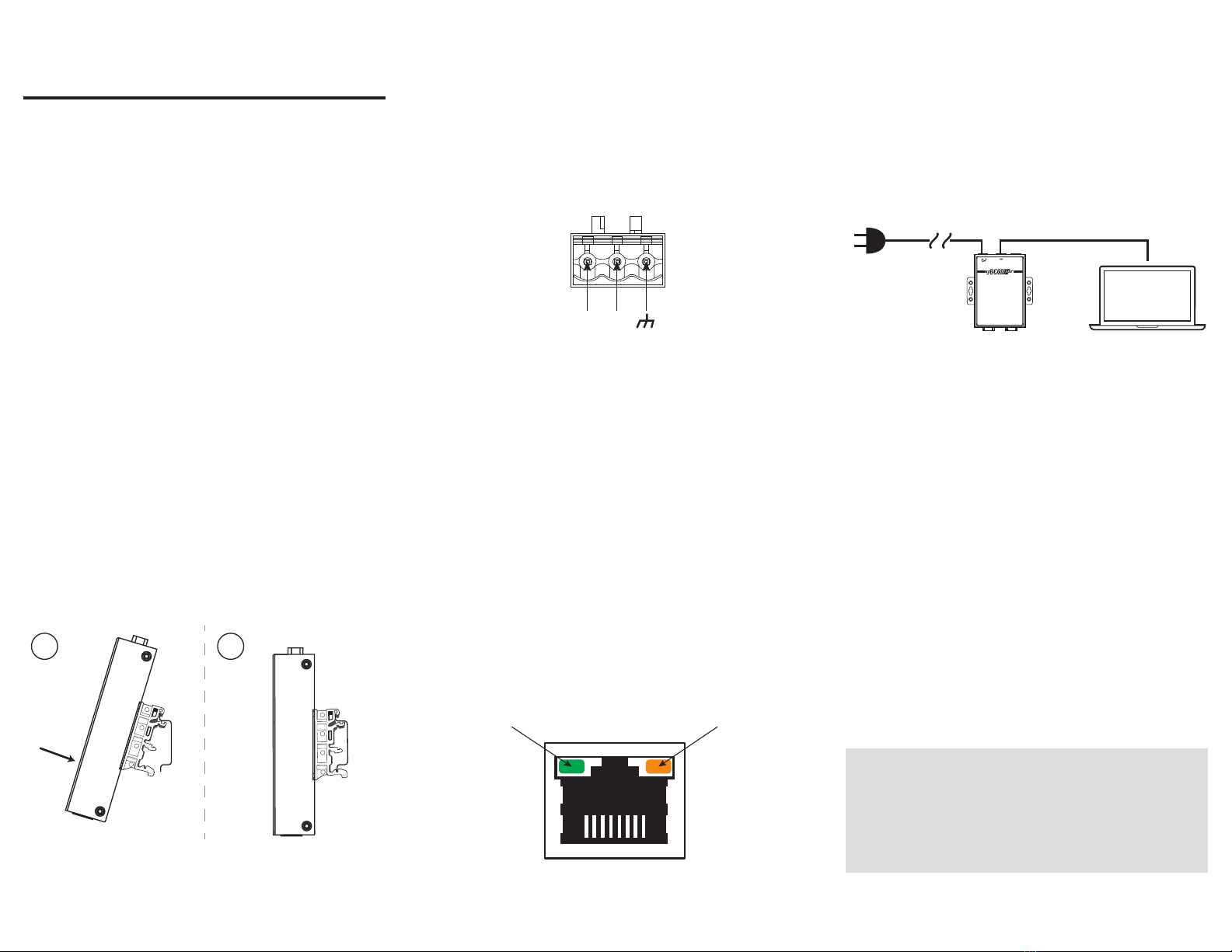
Connecting the Power
Connect 9-48 VDC control power to the Event
Manager’s input terminal block. The Power LED will
glow a solid ‘green’.
The terminal block is suitable for 12 - 30 AWG
(3.3 to 0.05mm2)wire
Input Rating: 9 to 48 VDC, 4W
Grounding: Run the ground connection from the
terminal block connector to the grounding surface prior
to wiring the power.
Ethernet: The Ethernet port is located on the top of
the unit. The LED indicator in the upper left corner
glows a solid green when the computer establishes a
connection with a 100 Mbps Ethernet network. The LED
indicator in the upper right corner glows a solid orange
when the computer establishes a connection with a
1000 Mbps Ethernet network. (gure 3)
The CyTime Event Manager is mounted to a standard
DIN rail by engaging the top edge rst, then locked into
place as shown:
1. Start by engaging the upper edge of the
DIN-mounting brackets with the top of the DIN rail
as shown (gure 1, step 1)
2. Then push the bottom of the unit until the bottom
latch of the DIN mount snaps into place (gure 1,
step 2)
To uninstall, pull down on the lower DIN mounting clip
and pull the bottom of the unit towards you. (reverse of
the installation)
The CyTime Event Manger is a single point
of reference for multiple sequence of event
recorders, providing an overall view of the
diagnostic health of your critical power system.
The CyTimeTM Event Manager provides the ability to
view and monitor input/output (I/O) status from
multiple Sequence of Event Recorders (SERs) in one
easy to read web interface.
The Event Manager allows the user to consolidate
events from all downstream SERs pertaining to a single
incident, providing powerful event reconstruction
analysis. Setup of the CyTime Event Manager is simple,
and takes only a few minutes.
Quick Start Guide
Installation
DIN Rail
DIN Rail
1 2
V+ V-
Direct Connection to PC:
1. Connect the Cytime Event Manager LAN1 Port to
your PC, using a standard Ethernet patch cable.
(Special crossover cable is not required)
2. Set PC to use static IP address of: 169.254.1.11
3. Apply power to the Event Manager
4. Open a standard web browser, such as CHROME
5. Type the default IP address of the Event Manager
(169.254.1.10) into the web browser
6. Enter the default user name (admin) and password
(csi_unit serial number) and click the ‘Login’ button to
access the home page
7. Click the ‘Setup’page tab, then click‘Network’. Change
the network settings to those provided by your network
administrator and click‘Apply’ to save. The Event
Manager will then reboot.
8. Disconnect the Ethernet patch cable and connect the
Event Manager to the local area network
9. Restore your PC to its previous network settings.
TIP: Obtain the desired settings from
your network administrator for:
-IP Address
-Subnet Mask
-Default Gateway
100 Mbps Indicator 1000 Mbps Indicator
EMS-100
CyTime Event Manager
Ethernet Cable
LAN 1
CyTime Event
Manager
PC
Power
Figure 1
Figure 2
Figure 3
Figure 4


