CyClone 866F User manual

© 2006-2011 All Rights Reserved
Ver. 2.4, Apr.’11
MOTORCYCLE SECURITY
ADVANCED MOTORCYCLE SECURITY
866F
TM

Thank you for purchasing this CYCLONE
866F Motorcycle Security System. The
866F is a state of the art device that will
provide you with years of trouble free
service if used properly. Please famil-
iarize yourself with the content of this
Owner’s Guide to get the most out of
your new system. We trust you will enjoy
using the product.

© 2006-2011 ALL RIGHTS RESERVED.
NOTICE! Although reasonable efforts have been taken to ensure accuracy in this
Owner’s Guide, FreyMoto Industries shall not be held liable for any errors, omis-
sions, property damage, loss or injury resulting from the use of this information.
All product specifications and features are subject to change without notice.
TABLE OF CONTENTS
Limited Lifetime Warranty................................... 1
Technical Specifications ................................... 2
Alarm Unit ............................................. 2
Status LED ............................................. 2
Transmitter ............................................ 2
System Overview.......................................... 3
Hardware ............................................. 3
Options ............................................... 3
Included Items ......................................... 3
Main Features Explained ................................... 4
Installation ............................................... 5
Before You Begin ....................................... 5
Connecting & Mounting the Alarm Unit .................... 6
After Installation Testing ................................. 8
Shock Sensor Adjustments ............................... 9
System Operation ......................................... 4
Transmitter Functions................................... 11
Feature Programming .................................. 14
Transmitter Learning ................................... 17
Troubleshooting .......................................... 18
Quick Reference Guide ................................... 19

1
© 2006-2011 ALL RIGHTS RESERVED.
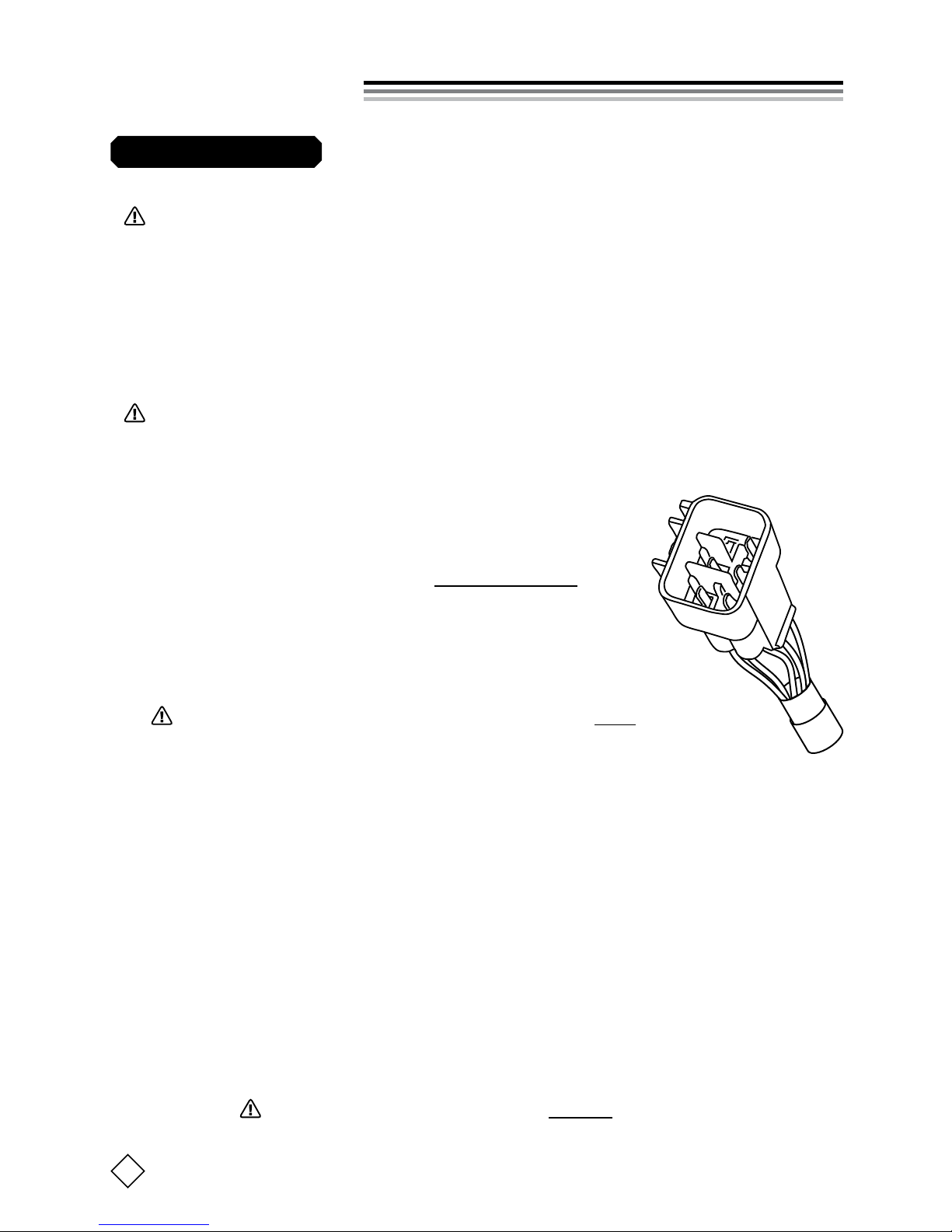
The CYCLONE 866F system alarm unit and transmitter are backed by a lim-
ited lifetime warranty against defective components and/or improper prod-
uct assembly to the original purchaser for as long the vehicle is owned by
that same purchaser, contingent upon proper product installation. All prod-
uct warranties become void if the CYCLONE 866F system was not installed
properly or the system is moved to another vehicle. All other parts and/or
accessories that connect to CYCLONE 866F systems, including the internal
backup battery, are warranted for one (1) year from the original date of pur-
chase. Any damage caused to the alarm system by internal backup battery
failure is covered only for one (1) year from the original date of purchase.
(Transmitter batteries are not covered under this warranty.)
During the warranty period, FreyMoto will repair or replace, at its sole dis-
cretion, any system component that is found defective in material or as-
sembly during the warranty period, provided that the product is returned to
FreyMoto with a clear and legible copy of the original purchaser’s receipt.
Any malfunction or damage to your CYCLONE 866F system that results
from water, electronic shorts, normal wear-and-tear, accidents, improper use,
neglect, faulty wiring, charging or changing the bike’s battery without rst
disconnecting Cyclone’s main wiring harness, incorrect installation, improper
mounting, opening the alarm unit case without written approval to do so
from FreyMoto, alteration or repair outside FreyMoto or its certied dealers
immediately voids this warranty.
This warranty is limited to defective parts only and does not provide any
compensation whatsoever for damages associated with the CYCLONE 866F
system or its accessories. This warranty does not cover installation labor,
product removal and/or reinstallation fees. This warranty is valid for the
original purchaser only and may not be transferred to another party. Frey-
Moto makes no warranty against theft or vandalism of the vehicle in which
the CYCLONE 866F system was installed. This warranty shall not be inter-
preted as an insurance policy against loss, nor shall FreyMoto be liable any
in way for such loss, nancial or otherwise.
WARNING! DO NOT ATTEMPT TO INSTALL THIS CYCLONE 866F PRODUCT YOUR-
SELF UNLESS YOU HAVE SPOKEN TO FREYMOTO IN ADVANCE TO LEARN WHAT
IS REQUIRED. YOUR WARRANTY IS VALID WITHOUT PROFESSIONAL INSTALLA-
TION, HOWEVER PROFESSIONAL INSTALLATION IS HIGHLY RECOMMENDED.
Limited Lifetime Warranty

2
CYCLONE 866F OWNER’S GUIDE
Technical Specifications
Operating Voltage:
Current Consumption:
Int. Battery Charging:
Int. Batt. Siren Duration
:
LED Flashing (Armed):
Operating Temp.:
Siren Blast Volume:
Siren Chirp Volume:
Housing:
Alarm Unit
Transmitter
TRANSMITTER NOTES:
•Even though the transmitter is waterproof, it is not advised to swim or
surf or dive with the transmitter, or press buttons underwater. If water
does get inside, immediately remove the batteries and allow to thor-
oughly dry out for 24 hours.
•Avoid leaving in direct sunlight for extended periods, and avoid leav-
ing near sources of intense heat.
•There are no screws used to hold the case together. To open, you may use
a at head screw driver, but note that excessive force may dent the plastic.
12Vdc (8v min.; 15v max.)
Armed or Disarmed = 4.9mA (@8.0~13.0vdc, AVG.);
Full Siren Blast = 270mA; SLEEP = 1.7mA
(
Immob. Off
)
Approx. 3~7 hours (while IG=ON, Temp. = 0~65°C)
1 hour (battery used only when 12v line is cut)
1 flash every 2 sec. (
LED is off when Disarmed/SLEEP
)
-20°C to +65°C (
limited by specifications of int. batt.
)
120dB @ 30cm/1ft. (105dB when driven by int. batt.)
110dB @ 30cm/1ft. (“Soft Chirp”)
Water-resistant (not “waterproof”)
RF Output:
Digital Code:
Batteries:
Transmit Range:
Batt. Life:
Housing:
303.875MHz (SAW filter)
66-bit Rolling Code (anti code grabbing)
Two CR1616, 3V Lithium cells
15m / 50ft. (typical in-city use)
1 year avg. @ 6 presses per day
Waterproof (submergible to 2 meters)
Status LED
Light Color:
Housing:
Blue
Waterproof (intended for outside-bike use)

CYCLONE 866F OWNER’S GUIDE
3
QTY DESCRIPTION DIMENSIONS (mm)
1Alarm Unit 58 x 83 x 28
1Transmitter 32 x 52 x 14
12-Sided Tape (for Alarm Unit) 42 x 1.2
2Wire Ties (for Alarm Unit) 250 (length)
1Mini Phillips (+) Head Screw Driver 42 (length), 3 (head)
1Universal Installation Harness 1500 (wire length)
1LED 20 (body diameter)
1500 (wire length)
System Overview
• World’s smallest all-in-one security system for motorcycles.
• Built-in Digital Tilt Sensor (3° alarm trigger)
• Built-in 2-stage Shock Sensor (separate adjustments for 1st/2nd stages)
•
Built-in High Power 120dB Piezo Siren
(selectable 10s or 30s blast duration)
• Built-in Backup Battery (activates siren if Armed & main power disrupted)
• Built-in Starter Immobilizer Relay (25A “switching”)
• Waterproof System Status LED (cool blue illumination)
• Waterproof 2-button rolling code RF transmitter (266 codes)
• Water-resistant Alarm Unit Housing
Hardware
Included Items
Options
• Pro Install Kit (bike-specific kit that makes installation faster and easier)
• Spare/Replacement 2-Button Transmitters
• Pager Output for adding 3rd party paging or tracking systems.

© 2006-2011 ALL RIGHTS RESERVED.
4
Main Features Explained
• Digital Tilt Sensor
When armed, system records bike inclination on two separate axis. If bike is
then tilted ±3° or more on either axis, the siren will be triggered. Note that the
siren may trigger even when bike has not been tilted due to the shock sensor.
• 2-Stage Shock Sensor
When armed, system can be set to trigger Warning Chirps and/or Full Siren
Blast based on the level of shock to the bike. Sensor 1st and 2nd stage triggers
are user-adjustable, and either setting or both can be turned completely off.
• Starter Immobilizer
Used to cut ignition or fuel lines when system is Armed (optional in Sleep).
• Panic Siren
Allows siren to be activated via transmitter to alert others in an emergency.
• Sleep Mode
Shuts down most functions to conserve power. Useful to prevent battery
drain when bike not used for extended periods. Also acts as a Valet mode.
• Silent Mode
Disables full siren blast and Warning chips, but allows Conrmation chirps.
Useful when using an optional paging system without alerting the thief.
• Manual Disarm
Allows you to disarm the system if you lose your transmitter or its battery dies.
(See bottom of page 11 for details.)
• Auto Arm
NOTE: CYCLONE will never Auto Arm while the Ignition is on.
Enabled by default. When enabled, Arms 5 min. after the ignition goes off.
You can also program which sensors are to be enabled for Auto Arm (pg. 14).
• Sector Bypass System (SBS)
Prevents siren from becoming a public nuisance. Shock, tilt or ignition sensors
will be individually bypassed if they trigger 5 times. You can disable this feature.
• Siren Trigger Memory
When you disarm, system informs you (via siren chirps and LED ashes) if
the siren went off in your absence.

5
© 2006-2011 ALL RIGHTS RESERVED.
I ns ta l l at i on
WARNING! Never route security system wires in a way that would im-
pede safe operation of the vehicle in which you are installing. Ensure the
operator of the vehicle cannot become tangled in security system wires or
otherwise be hindered in a way that could cause a trafc accident. Take
time to ensure all wiring is connected, mounted and covered so that electri-
cal shorts will not occur. As the installer, you are responsible to verify the
safety of your work.
Before You Begin
POINTS TO CONSIDER:
• This system is only intended for use in vehicles with 12v batteries.
• The 5-pin Alarm Unit main wiring connector
(pictured at right) which mates with the included
Installation Harness is waterproof but the other
two (smaller) connectors are not waterproof. Pro-
tect the smaller 2-pin connectors from water.
• If you need to disconnect or charge your bike’s bat-
tery, FIRST disarm then disconnect main wiring har-
ness at the connector AND THEN disconnect the battery.
Failure to disconnect the Cyclone harness rst could result
in damage to Cyclone’s speaker or other alarm components!
• When operating the 866F, if you see smoke or detect some abnormal
operation, immediately discontinue using the system and consult with
the vendor who sold you the CYCLONE system.
• In cases where the bike is not driven for an extended period (greater
than 2 weeks) or in the event the battery voltage is already very low,
it is strongly suggested to either use SLEEP mode or start the engine
from time to time to ensure the battery does not die. You may also wish
to check the battery voltage now and then if you have other 3rd party
electronics installed.
• If the battery dies or the voltage level drops very low, the 866F may not
have adequate voltage to function properly. In this case, you will not be
able to start the engine (due to the immobilizer) until the battery is re-
charged. Disconnect Cyclone’s harness before charging your battery!

6
CYCLONE 866F OWNER’S GUIDE
1. Ensure the bike’s battery is connected and the Installation Har-
ness is properly installed.
2. Plug the Installation Harness connector into the 5-pin Alarm
Unit main wiring connector. Note that the full alarm blast will go
off when the connection is made. Press button-1 on the transmitter (for
about 1 sec.) to stop the siren sound. The siren will then chirp 3 times
to conrm the system is disarmed. (If you later need to disconnect the
vehicle battery, remember to rst disconnect the Alarm Unit main wiring
connector and then you may proceed with disconnecting the battery.)
3. Consider a mounting location for the 866F alarm unit some-
where inside the seat. ALWAYS PROTECT THE ALARM UNIT
FROM WATER! Keep in mind that your mounting location may impact
the range of the transmitter. If you later nd the transmitter range
to be unacceptable, you will need to relocate the 866F alarm unit. For
this reason it may be best to avoid afxing the 2-sided tape or the wire
ties until you have conrmed that the transmitter range is acceptable.
(Included tape is useful for at-surface mounting, while the wire ties are
for mounting the alarm unit on a support bar.)
IMPORTANT! The installation described here does not include details
of connecting the Universal Installation Harness. Please consult the CY-
CLONE Installation Guide for a detailed wiring diagram and further in-
structions. Once the Universal Installation Harness is installed, you may
then continue the installation according to the following 4 steps.
Connecting & Mounting the Alarm Unit
CAUTIONARY POINTS:
• Although the 866F alarm unit is water-resistant, it must NEVER be
submerged in water. Your installation location must NEVER allow wa-
ter to collect around, spray onto, or ow over the alarm. Install only
where protected from the outside elements, such as within the seat. WA-
TER DAMAGE IS NOT COVERED UNDER WARRANTY.
• Do not leave the 866F mounted in locations with condensing humidity, high
temperatures, and/or a high concentration of dust or airborne particles.
I ns ta l l at i on

7
Proper Mounting Tips. Mounting the 866F alarm unit on its side (with
the siren facing to the side instead of straight up) may cause sensitivity
problems for the onboard tilt sensor. Prior to mounting, it is recom-
mended that you rst test the operation of the tilt sensor to conrm it
will work in your intended mounting position. To help you decide an
appropriate mounting position, please consider Fig. 1 below.
PERPENDICULAR TO GROUND
+45°
-45°
GROUND
LEVEL
+45°
-45°
GROUND
LEVEL
NEVER MOUNT WITH
SIREN FACING DOWN
Positioning the alarm unit for maximum tilt sensitivity
FIG. 1
As shown, the tilt sensor achieves maximum sensitivity when the siren
is mounted face-up. Sensitivity declines rapidly for tilt angles outside
the ±45° shown (on two axis).
For some bikes, vertical mounting may be the only means of installing
the alarm unit. In this case the tilt sensor may still work, but the sen-
sitivity will be adversely affected. This may or may not be acceptable to
the user. However, you must avoid mounting the alarm unit face down
because it may cause the tilt sensor to false-trigger the siren.
4. Now it’s time to connect the Status LED. Note
that there are two “2-pin” connectors at end of the
alarm unit harness. The larger of the two plugs
is for connecting to an optional paging system. The
smaller connector is the one you plug into the LED
connector.
I ns ta l l at i on
CONNECTING & MOUNTING THE ALARM UNIT

8
CYCLONE 866F OWNER’S GUIDE
After Installation Testing
SHOCK SENSOR. When light shocks are administered to the bike, the
siren should generate 2 chirps. Harder shocks should trigger the full siren
(10 or 30s). If the factory default shock sensitivity is undesirable, adjust-
ments can be made by removing the rubber cap on the alarm unit and
adjusting the two POTs with the included screw driver — don’t twist too
hard! See “Shock Sensor Adjustments” on the next page for details.
IGNITION SENSOR. Switch ON the Ignition and the siren should blast
for 10 or 30 sec. If the Ignition remains ON, the siren should blast again
after a 45 second delay (LED ashes on/off 30 times—the highest Manual
Disarm Code). If SBS is set to ON, then the siren will cycle on and off up
to 5 times and then stop. With SBS off, the siren will cycle on and off an
unlimited number of times, as long as the ignition switch is turned on.
IMMOBILIZER. When the 866F is Disarmed, the internal relay should
switch closed when IG is turned on (WHT & GRN wires are shorted). The
relay remains switched for 20 sec. after IG is turned off. When Armed,
the relay will switch open when IG is turned on to prevent engine starting.
AUTO ARM. If you don’t want Cyclone to Auto Arm 5 minutes after you
turn off IG, please see pg. 14. (Also see “Auto Arm Sensor Enable” on pg.14.)
TILT SENSOR. With Cyclone Armed, tilt the bike on two axis (see diagram
below) and ensure the siren blasts for 10 or 30 sec. (program preset). After
an 8 sec. delay, the siren should go off again if the bike remains tilted.
(NOTE: After tilting, it may take up to 3s for the siren to go off.)
I ns ta l l at i on
After connecting, run the LED to a suitable location on the bike, prefer-
ably near the ignition keyswitch (for visibility). The circular LED body
is waterproof, so you are relatively free to mount it anywhere, so long as
the 2-sided tape on the bottom can adhere to the mounting surface.

CYCLONE 866F OWNER’S GUIDE
9
BACKUP BATTERY. If you have at least 3 hours, turn on the Ignition and
allow Cyclone’s internal battery to charge. When charged, you should be
able to disconnect the Cyclone’s main 5-pin harness and hear the siren go
off (only when Armed & IG is off). (Siren will go off for up to 1 hour when
the battery is fully charged. A full charge could take up to 7 hours.) To stop
the siren, reconnect the main wiring harness and Disarm. (If the siren
went off until the battery died, it will go off again when power is connected.)
I ns ta l l at i on
Shock Sensor Adjustments
Sensitivity POTs. Remove the rubber cap, located just above the siren
speaker on the front of the Alarm Unit. You will then see two small holes
for accessing the shock sensor adjustment potentiometers (POTs). See
Fig.3 on the next page. ALWAYS put the rubber cap back on properly or
water could destroy the electronics! Such is NOT covered under warranty!
Screw Driver. Adjustments can easily be made using the included mini
Phillips (+) screw driver. (Don’t twist too hard or you will break the POTs!)
Note the arrow on the side of the screw driver handle. This arrow can help
you be more precise in your adjustments by indicating what sensitivity
level you are at, with respect to the illustrations in Fig. 2 below.
FULL TRIGGER ADJUSTMENT
(hard shock detection)
OFF MAX
WARNING TRIGGER ADJUSTMENT
(light shock detection)
OFF MAX
100°
225°
270°
ADJUSTABLE
RANGE
Shock sensor factory default settings for Full & Warn triggers
FIG. 2
When you insert the screw driver into the adjustment holes, try to align
the arrow on the handle in the same position as the arrows shown above in
Fig.2. If you nd the shock setting is different from the factory default, or
if you twist by mistake, simply turn both POTs to the far left OFF position,
then align the arrow on the screw driver to the OFF position, and then you
can adjust as appropriate. In this way, the arrow on the screw driver han-
dle will show you precisely where you are in the 270° adjustment range.
0° 270° 0° 270°

10
I ns ta l l at i on
Adjust “Warn Trigger” First. It is important to ad-
just the Warn Trigger before the Full Trigger. This
is because the Warn Trigger adjustment denes the
“maximum sensitivity level” of the Full Trigger. If
you turn the Warn Trigger completely OFF, for exam-
ple, the Full Trigger is also automatically set to OFF.
Conversely, the higher (closer to MAX) you set the
Warn Trigger, the greater range of control you have
over the Full Trigger. Simply put, the Full Trigger
can never be more sensitive than the Warn Trigger.
This is illustrated graphically in Fig. 4 below.
Warn TriggerFull Trigger
Sensitivity POTs
FIG. 3
FULL
OFF
MAX Sensitivity
WARN
OFF
MAX
(225°) 83%
SETTING
SETTING
37% (100°)
Sensitivity
FULL
OFF
MAX Sensitivity
WARN
OFF
MAX10%
SETTING
SETTING
100%
Sensitivity
FACTORY DEFAULT SETTINGS EXAMPLE SETTINGS
Relationship between Warn & Full shock sensor adjustment ranges
FIG. 4
In Fig. 4 above, you can see that the “factory default settings” (also shown
in Fig. 2) allow a wide range of adjustment for the Full Trigger, without
making the Warn Trigger overly sensitive. In the “example settings” bar
graph shown, the Warn Trigger is set to 10% of Max. And even though
the Full Trigger is set to 100% of Max in this example (POT turned all the
way to the right), the adjustable range of the Full Trigger is very narrow
because it’s Max sensitivity is dened by the Warn Trigger setting. To get
more sensitivity out of the Full Trigger, you must rst set the Warn Trig-
ger sensitivity higher.
The 866F shock sensor digitally lters out “environmental vibrations” (e.g.,
large truck driving nearby, wind, rain, jackhammers, etc.) in order to mini-
mize false triggers. However, please note that setting the Warn Trigger to
Max may cause the 866F to detect these otherwise “harmless” vibrations.
SHOCK SENSOR ADJUSTMENTS

CYCLONE 866F OWNER’S GUIDE
11
11
System Operation
Transmitter Functions
ARMING (Also see “Auto Arm” on pages 15-16)
• With Tilt Sensor
and
Shock Sensor Enabled
Ensure IG key is turned off. Press Btn-1 on the transmitter
for about 1 second and then release. (Note that the 866F
will Arm automatically 5 minutes after IG is switched off.)
If Arming was successful, the siren will chirp 1 time, and
the LED will ash 1 time; then 5 seconds later, the system
Status LED will start ashing continuously and both sen-
sors will become active.
• With Tilt Sensor
or
Shock Sensor Enabled
By default, pushing Btn-2 to Arm enables only Tilt and dis-
ables Shock. You can disable Tilt and enable Shock by chang-
ing the “Single Sensor” setting (see page 14, Feature No.3).
Pushing Btn-2 results in 1 siren chirp and 1 LED ash,
and then 5 sec. later the LED will ash continuously and
your Single Sensor choice will become active.
NOTE: During the rst 5 seconds after arming, the sensors are not yet
active. Please avoid tilting or shaking the bike during this time.
DISARMING
With the Ignition key off, press either transmitter but-
ton for about 1 second and then release. If Disarming
was successful, and if the siren was not triggered in your
absence, the siren will chirp 3 times and the Status LED
will ash 3 times. See Table-1 for details on the different
siren chirps and LED ashes produced after Disarm.
Manual Disarming (useful if the transmitter is lost or battery dies)
Turn IG on and the full siren blast should go off. During the 10s or 30s
siren blast, turn IG off. When the siren blast stops, you have 8 sec. to
turn on IG again. Keep your hand on the Ignition key and count the
number of Status LED ashes. When the number of ashes matches
your Disarm Code (see pages 14 & 16), turn IG off. The siren should
then chirp 3 times, indicating the system is now disarmed.
Push Button-1
Push Button-2
Push Either
Button
NOTE: Ignition = “IG” in this guide.

12
TRANSMITTER FUNCTIONS
PANIC SIREN
With IG key off, press both transmitter buttons for about
1 second. The siren will then go off for 10s or 30s. Push
either button to stop the siren. When the siren sequence
stops, Cyclone will arm itself.
SILENT MODE
Stops siren triggers but allows Arm/Disarm conrmation
chirps. Useful with an optional paging system, alerting
you to theft attempts without the thief knowing.
Activate.Disarm and within 20 sec. turn on IG, then
press transmitter Btn-1 (about 3 sec.) until the si-
ren chirps 1 time. Turn off IG. Press Btn-1 to Arm.
Deactivate.Disarm and within 20 sec. turn on IG, then
press Btn-1 until the siren chirps 2 times, then turn off IG.
SLEEP MODE
This mode allows you to conserve vehicle battery power
by reducing the electric current consumption of the 866F.
This feature is useful when you will not be riding the bike
for extended periods. All security features are disabled by
default. You can enable the Starter Kill Immobilizer for
greater security (avg. current consumption < 2mA).
TIP: Sleep Mode also acts as “Valet Mode,” useful to disable
security features when sending the bike in for maintenance.
Activate Sleep.Disarm Cyclone, and within 20 sec. turn on IG and
press Btn-2 (about 3 sec.) until you hear 3 siren chirps in rapid succes-
sion. The 3 chirps conrm that Sleep Mode is activated. Turn off IG.
System Operation
Push Btn-1
for 3 sec.
Push Btn-2
for 3 sec.
Push Both
Buttons
NOTE. Within 20 sec. of activating Sleep Mode, if you turn IG off
and then press a transmitter button, you will enable the Starter Kill
Immobilizer in Sleep Mode. This will cause the status LED will ash.
See next page for details on Enabling/Disabling the Immobilizer.

TRANSMITTER FUNCTIONS
13
ENABLE Starter Kill Immobilizer. While in Sleep Mode, turn on
IG for 3 sec, then Turn off IG and within 20 sec. press either
transmitter button (about 1 sec.) until the siren chirps 1
time. The status LED will now ash continuously. (If IG
goes on with the Immobilizer on, the siren won’t trigger.)
DISABLE Starter Kill Immobilizer. Turn on IG and
wait 3 sec. Within 20 sec. press either transmitter button
(about 1 sec.) until the siren chirps 3 times. The status LED
will stop ashing. (To then disabled Sleep Mode, see below.)
Deactivate Sleep.Turn on IG and wait 3 sec.
Within 20 sec.
press but-
ton-2 (about 3 sec.) until you hear 5 siren chirps. The 5 chirps conrm
that Sleep Mode is now deactivated. You can now turn off IG.
(If you
hear only 3 chirps, it means you merely Disabled the Immobilizer. Turn on
IG and press Btn-2 again (3sec.) until you hear 5 chirps to Deactivate Sleep.)
LOST TRANSMITTER WHILE IN SLEEP. If you lost your only transmitter,
please start by purchasing a replacement from your Cyclone dealer.
Next, ensure IG is off, and then Disconnect Cyclone’s main harness
(noting that the siren may blast due to the backup battery), wait a few
seconds, then reconnect the harness. Sleep Mode is now deactivated.
Now use Manual Disarming (pg. 11) to Disarm. After Disarming, quick-
ly perform Transmitter Learning steps 2, 3 & 4 as described on page 17.
TABLE-1 Siren & Status LED Response to Changes in System State
ACTION or STATE SIREN STATUS LED
Arming 1 chirp 1 flash
Disarming (nothing triggered) 3 chirps 3 flashes
Disarming (Shock triggered) 3 + 1 chirps 3 + 1 flashes
Disarming (Tilt triggered) 3 + 2 chirps 3 + 2 flashes
Disarming (Ignition triggered) 3 + 3 chirps 3 + 3 flashes
Armed —
Short flash every 2s
Warn Trigger 2 chirps 2 flashes
Full Trigger 10s or 30s Flashes for 10/30s
Panic Siren 10s or 30s Flashes for 10/30s
Sleep Mode + Immobilizer Enabled disabled
Short flash every 2s
System Operation
Push Either
Button

14
CYCLONE 866F OWNER’S GUIDE
System Operation
Feature Programming
TABLE-2 Feature Selection Menu
No. Feature Description Selection Chirps
1Auto Arm Sensor Enable
(tied to No. 3 “Single Sensor” below)
Both Sensors 2
Single Sensor 1
2Shock Sensor “Full Trigger” ON 2
OFF 1
3Single Sensor
(for Btn-2 Arming & Auto Arming)
Tilt 2
Shock 1
4Duration of Full Siren Blast 30 sec. 2
10 sec. 1
5Sensor Bypass System (SBS) ON 2
OFF 1
6Auto Arm ON 2
OFF 1
7Manual Disarm Code 66
8Rest Settings to Factory Default Press Btn-2 until siren chirps 8
FACTORY DEFAULT SETTINGS ARE BOLD & HIGHLIGHTED ABOVE
1) Arm and then Disarm Cyclone.
2) Within 20s of Disarming, turn on the Ignition.
3) Within 5s of turning on the Ignition, press both transmitter buttons (at
the same time) until the Status LED lights solid (press for about 5s). (If
you hear 1 or 3 chirps, you’ve entered Silent or Sleep Modes by accident.)
4) Press button-1 the same “No.” of times as the feature you want to change
in Table-2. The siren will chirp and LED will ash the same “No.” of times
as the feature you chose. You now have 20s to change that feature.
5) Press button-2 to toggle the feature “Selection.” The siren will chirp and
LED ash according to the new Selection (see “Chirps” column below).
6) To program another feature, repeat Steps 4 & 5. To exit Feature Pro-
gramming, turn off the Ignition. The LED will then ash according to the
number of your Manual Disarm Code, and then the siren will chirp 3 times.

FEATURE PROGRAMMING
15
System Operation
Description of Programmable Features
NOTE: When you select any of the 8 programmable features, the siren will
chirp the same number of times as the feature you just selected, and the
Status LED will also ash the same number of times. When exiting the
Feature Selection Menu, the Status LED will ash the same number of
times as the Manual Disarm Code and then the siren will chirp 3 times.
1. Auto Arm Sensor Enable.Allows you to choose either a single sensor
or both sensors to be active when the 866F automatically Arms. You
can choose your preferred “Single Sensor” in Feature No. 3 (see below).
2. Shock Sensor “Full Trigger.” When set to OFF, even hard shocks
produce only Warning Chirps. Of course, you could just turn off the
shock sensor Full Trigger (10/30s siren blast) simply by turning the sen-
sitivity POT all the way to the left (see pages 9-10). But this program-
mable feature allows you to disable the Full Trigger while keeping your
desired Full Trigger level set on the POT. This is useful if you some-
times wish to disable the Full Trigger and then later re-enable it. (SBS
still limits “hard shock” triggers—see Feature No. 5 below.)
3. Single Sensor. Allows you to choose either the Tilt sensor or the Shock
sensor to become active during these two conditions: (1) Auto Arm and
(2) Button-2 Arming. (This feature is tied to feature No. 1 above.)
4. Duration of Full Siren Blast. You can program the siren to go off
for either 10s or 30s. The Full Siren Blast goes off during a Shock Sen-
sor Full Trigger, Ignition Switch Trigger, Digital Tilt Trigger, Panic Si-
ren mode, and when the power is cut to the system while Armed (siren
sounds via Cyclone’s internal backup battery).
5. Sensor Bypass System (SBS). SBS prevents the 866F from becoming
a public nuisance. With SBS on, the system will individually bypass the
Tilt sensor, Shock sensor (Full Trigger only), or the Ignition sensor after
each sensor triggers 5 times. For example, if the Tilt sensor triggers 5
times, SBS will disable it but the Shock and Ignition sensors remain ac-
tive (until they too individually trigger 5 times). If noise pollution is not
an issue for you, SBS can be turned off.
6. Auto Arm. Set to ON by default. When programmed ON, Cyclone
will Arm itself automatically 5 minutes after the Ignition goes off.
(Turning the Ignition off is what activates the Auto Arm timer. Cyclone
will not Auto Arm at all if you merely Disarm with the transmitter.)

16
CYCLONE 866F OWNER’S GUIDE
System Operation
7. Manual Disarm Code. Manual disarming is useful if your transmitter
is lost or the battery dies. The factory default code is set to: 6. This fea-
ture allows you to set your own code. (30 possible code choices)
When you select this feature with transmitter Button-1, the siren will
chirp 7 times and the Status LED will ash 7 times. Now push Button-2
and the Status LED will then light solid for 10 seconds and then start
ashing slowly, up to 30 times. You must program your code during the
time that the LED ashes 30 times.
When the LED ashes the same number of times as the code you wish to
set, immediately turn off the ignition. The Status LED will then blink
the same number of times as the code you just programmed, and the siren
will chirp 3 times, and this will auto-exit the Feature Selection Menu.
For example, let’s say you wish to set your secret code to “1.” In this
case, you would enter the Feature Selection Menu and select feature No.
7 using transmitter Button-1 (the LED will blink 7 times to conrm).
Now press Button-2 and the LED will glow solid for 10 seconds. When
the 10 sec. is nished, the LED will turn off and then blink once — now
quickly turn off the Ignition. If you turned off the Ignition in time, the
LED will then blink once (to conrm your new code) and the siren will
chirp 3 times.
8. Reset Settings to Factory Default. If you have altered the settings in
the Feature Selection Menu, this feature will allow you to restore all set-
tings to their factory default, as shown in Table-2 on page 14.
When you choose Feature No. 8, the siren will chirp 8 times and the Sta-
tus LED will ash 8 times. After the 8 chirps nish, press and hold trans-
mitter button-2 until you hear 1 siren chirp (press for about 5 seconds).
If you heard the single chirp, all Cyclone feature settings are now reset.
The LED will now ash the same number of times as your Manual Dis-
arm Code, and then the siren will chirp 3 times to indicate Cyclone has
exited from Feature Programming.
Auto Arm TIPS: (1) Cyclone won’t Auto Arm while the Ignition is ON.
(2) If you like Auto Arm ON but somtimes want to Disable it, simply
Arm & Disarm after you turn off the Ignition. (3) Don’t forget that you can
program 1 or 2 sensors to be enabled during Auto Arming (Feature No.1).

CYCLONE 866F OWNER’S GUIDE
17
17
System Operation
Transmitter Learning
Transmitter Learning is useful if you wish to purchase an optional remote
for your 866F system, or if you lose your existing remote and require a
replacement. The 866F can store up to 3 transmitters total in memory.
When you learn new transmitters, all previously learned transmitters will
be deleted from memory for security. Therefore, each time you initiate the
learn process, you must re-learn all your transmitters.
Transmitter Learn Procedure:
1. Arm and Disarm the system. (If you lost all your remotes, you’ll need
to start by purchasing a new remote. With your new remote ready, ensure
IG is off, then kill power to Cyclone and restore power after a few seconds.
Next, use Manual Disarming as described on page 11, and then proceed
to Step-2 below.)
2. Within 20 sec. of Disarming, turn the Ignition key on and off 10
times. The Status LED will blink 10 times and then light solid on for
10 seconds. (If the Ignition is turned on at this stage, you will exit out of
transmitter learn, and the previously learned transmitters will remain
in memory.)
3. During the 10 sec. that the Status LED is lit solid, press and re-
lease button-1 on the rst transmitter you wish to learn. Previ-
ously learned transmitters will now be deleted, and the siren will chirp
1 time, and the Status LED will dim 1 time. REPEAT this step for all
other transmitters you wish to learn. You have 15 sec. to learn each
transmitter.
4. After all transmitters are learned, turn Ignition on and off. (Or
wait 5 seconds.) The Status LED should then blink the same number of
times as your Manual Disarm Code, and the siren should chirp 3 times.
NOTE. If you lost your transmitter while Cyclone was in Sleep Mode,
please refer to the “LOST TRANSMITTER WHILE IN SLEEP” note on
page 13.
Other manuals for 866F
1
Table of contents
Other CyClone Motorcycle Accessories manuals