Cyndar Electronic Technology XD-TOF-25 User manual

XD-TOF-25Lidar sensor operating instructions
·Product specification description
·Product operating instructions
·Product communication methods and protocols
Single-line Lidar Product Manual Series

Sensing the world ·Leading the change
1
Table of Contents
1 ............................................... 2
2...................................... 3
2.1 .............................. 3
2.2 ................................ 5
2.3 ................. 7
2.4 ................................ 9
2.5 .................................... 9
3 ................................ 11
4...................................... 13
4.1 .................................. 13
4.2 ................... 14
4.3 ................................ 39
4.4 ................................... 33
About
Product description
Equipment Specifications
Working principle
Influence of object surface on measurement
Ranging error ....
Area alarm ....
Equipment appearance
Device connection
Main interface
Device connection and communication
Operation routine
Client application
..
..
..
..
..

Sensing the world ·Leading the change
2
1
Follow all specified safety instructions and guidelines.
When using, please observe the local work safety regulations and general
Device profile.
This operating instruction provides important information about how to use lidar.
First, to ensure the safe operation of lidar, the following conditions must be met:
About
safety regulations.
Before starting any operation on the device, please read these instructions
carefully to familiarize yourself with the lidar sensors and their functions.
These operating instructions are intended to solve the technical personnel's guid-
ance on mechanical installation, electrical installation, commissioning, configura-
tion and maintenance, and are suitable for XD-TOF-25 lidar sensors.
This operating instruction contains the following information about XD-TOF-25:
product description. First, the basic parameters of XD-TOF-25 are provided, the
working principle of the device is given, and the requirements for the space
environment under different maximum ranging capabilities are proposed.
device installation. The main interfaces of the device and their respective
functions are listed in detail; a general operation specification for outputting
target distance information within the detection range and the communica-
tion protocol of XD-TOF-25 are proposed: the network port is connected to the
"TCP/IP" protocol The terminal outputs the distance information of the target
object in the scanning area. The user can convert the target distance informa-
tion into more intuitive information according to actual needs.

Sensing the world ·Leading the change
3
2
2.1
0.05-25m
905nm
I
≤66ms
0.33°
1.0mm
Ethernet
-10°~50°
DC
9-30V
< 3W
≤8W
10
Interface I
Interface II
※
XD-TOF-25
Product description
Equipment Specifications
Table 2-1 XD-TOF-25 equipment specification list
Parameter
Detection distance
Light source wavelength
Laser class
Minimum response time
Angular resolution
Output resolution
Interface
Operating temperature
Radar module
Voltage
Power consumption
(Heating module is off)
Heating module function
Programmable alert area
Support zone shape Convex polygon
Table 2-2 XD-TOF-25 device interface
Ethernet port
Power input/Digital
I/O/RS232
M8 connector D-code 4 holes
M8 connector type A code 5 holes
In the test version prototype, the RS232 interface is not yet open. This feature is
expected to be fully opened in the next version of the product

Sensing the world ·Leading the change
4
IP67
1 GB 7247.1-2012
GBT_17626.6-2008
GBT_17626.6-2008
GBT_17626.8-2006
40%、70%、80%、120% GBT_17626.29-2006
GBT_17626.2-2006
GBT_17626.4-2008
GBT_17626.5-2008
GB_9254-2008
GB_17626.3-2006
GBT_2423.10-2008
GBT_2423.5-1995
IP67 GB4208-2008
GB 4793.1-2007
500VAC GB 4793.1-2007
Table 2-3 Environmental adaptability parameters
Chassis protection level
Laser radiation safety level
Conduction CE
Conduction CS
Power frequency magnetic field
Voltage drop
Electrostatic discharge
Electrical fast-shift pulse train
Surge
Radiation RE
Radiation RS
Vibration
Shock
Enclosure rating
Electrical insulation
Dielectric strength
Level
A grade industrial grade
Level 3 10V/M
Level 5 100A/M
Level 2 4KV
Level 4 4KV
Level 2 1000V
A grade industrial grade
Level 3 10V/M
10-55Hz, 1.5mm double
amplitude, 2h each in X,
Y, and Z axes
150m/s² for 11ms
100VAC, not less than 1MΩ

Sensing the world ·Leading the change 5
2.2
0
10
20
30
-10
-20
-30
270°
Schematic diagram of the range measurement principle of the lidar sensor
XD-TOF-25
XD-TOF-25
Working principle
XD-TOF-25 is a scanning photoelectric lidar sensor. The emitted laser beam is reflected and
deflected by a mirror fixed on a rotating motor and scans the surrounding environment at a
fixed frequency. As shown in Figure 2-1, XD-TOF-25 has a two-dimensional sector area with
a scanning range of 270°. The maximum scanning distance is determined by the specific
model of the product. In each specific direction, XD-TOF-25 calculates the distance between
the obstacle and the radar at this angle by emitting a laser pulse with a short pulse width
outward and thinking the time between the pulse and the radar traveling to the obstacle. The
principle is shown in Figure 2-2.
Picture 2-1 Scanning area of lidar sensor
Fire pulse
Reflected pulse
Obstacle
Figure 2-2
The XD-TOF-25 lidar sensor emits laser pulses through a laser diode, and after related processing, it becomes a
Gaussian distributed circular spot and emits at a certain divergence angle. The beam exit diameter is 8mm. As the
detection distance increases, Figure 2-3 visually shows the beam divergence process, and Figure 2-4 shows the curve
of the spot size at different distances.
Figure 2-3 Laser pulses gradually diverge

Sensing the world ·Leading the change
6
D = 3mm + 0.010rad × U(mm)
0 10
515 2520
100
200
300
400
Beam Size(mm)
Distance(m)
Laser beam diameter at different detection distances
The relationship between the spot diameter D and the detection distance U is:
Figure 2-4
As shown in Figure 2-6, when the object to be measured at a specific distance is larger than the spot size of the
laser, the object to be tested can be stably detected. When the object under test is smaller than the laser spot size
at this distance, the smaller the area of the object under test that occupies the area of the laser spot, the easier the
object will be missed. Whether it is missed or not depends on the ratio of the measured object to the spot size,
the tilt angle of the object itself, the reflectivity of the object itself, etc. We will give the reflectivity requirements
for stable detection of objects in Figure 2-8. You can calculate the equivalent reflection according to Figure 2-6
and Equation 2-1 based on the object's inclination, the area of the object and the actual reflectivity of the object
The rate is compared with the curve shown in Figure 2-8.
Object projection area
Spot diameter
Laser exit direction
Object normal
Figure 2-5 Calculation of equivalent reflectance
Equivalent reflectance calculation: where η is the equivalent reflectivity of the object, is the
projection of the object in the radar exit direction, is the spot size, θ is the angle between the
surface normal of the object and the radar exit direction, and η is the reflection of the object itself
rate,
e
o
beam
o
S
S

Sensing the world ·Leading the change
7
= cos
o
oe
beam
S
S
-------------------------(2-1)
2.3
×θ×
ηη
Determined by the optical properties of the material
Object to be measured
Laser spot Laser spot
Object to be measured
Stable detection of objects Difficult to detect objects
Figure 2-6 Objects that are easily detected and objects that are not easily detected
With the increase of the laser transmission distance, the farther the distance between adjacent scanning mea-
surement points, in order to ensure that the scanning area does not break, a sufficient number of laser pulses
are needed to ensure angular resolution. The existing angular resolution of XD-TOF-25 is 0.33°. There are
811 laser pulses for each pair of two-dimensional plane scans. As shown in Figure 2-7
Figure 2-7
Influence of object surface on measurement
When the laser is incident on most surfaces, the radar will receive the echo signal in the form of diffuse
reflection in all directions. The stronger the reflection capability, the easier the radar will receive the echo
signal. The reflection characteristics of the laser will change with the surface material, structure and color.
Surfaces with high reflectivity (white, reflected light) can be detected better than surfaces with low reflectivity
(black, absorbed light).

Sensing the world ·Leading the change
8
0 10
515 2520
Distance(m)
10
15
20
25
30
35
5
Target Remissiom(%)
Scanning Range
Shows the reflectance characteristics of some common materials for your reference:
3%
4%
14%
20%
55%
68%
75%
87%
90%
130%
150%
200%
According to the definition of the standard reflectivity board in the national standard, we select objects with a
reflectivity of 3%-1000% (specular reflector) to calibrate the radar test capability. As the detection distance
increases, the minimum reflectivity of the detectable object surface changes. The minimum detectable reflec-
tance curve of XD-TOF-25 series products is shown in Figure 2-8: the vertical axis of the curve is the mini-
mum detectable reflection Rate (equivalent reflectance), the abscissa is the corresponding distance.
Table-2-2
Table 2-2
Figure 2-8
Material name
Black cloth
Black rubber
Opaque black plastic
Clean rough board
Newspaper
Cardboard box
Human palm
Opaque white plastic
White drawing paper
Unpolished white metal surface
Glossy light metal surface
Matte surface stainless steel
Common material reflectivity
Reflectivity

Sensing the world ·Leading the change
9
2.4
0.05-10m 10-15m 15-25m
20mm 20mm 35mm
15mm 20mm 30mm
Ranging error within different detection distances
1mm 1h
2mm 2h
3mm 3h No echo can be detected in this observation direction, and there is no
object that can be identified within the range.
4-50mm 4h-32h
50mm-500mm 32h—1F4h
500mm-
25000mm
1F4h—61A8
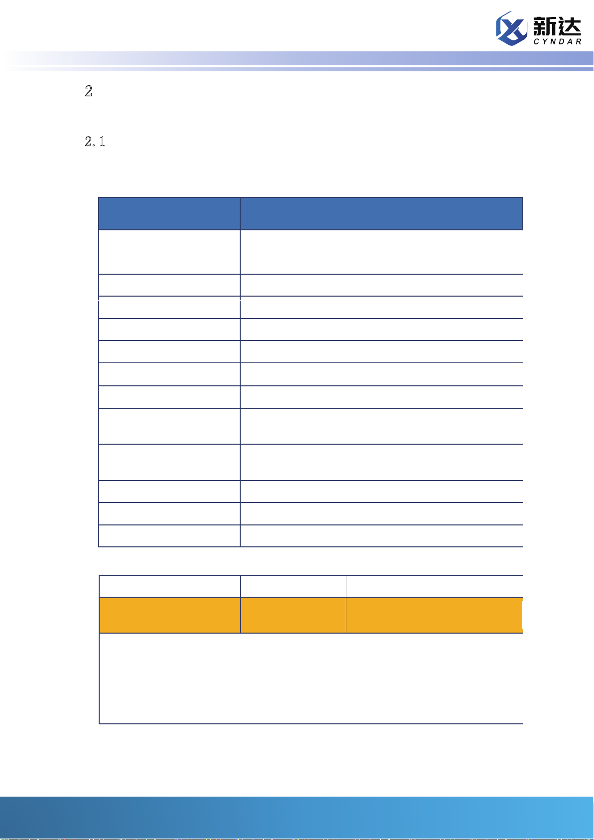
Ranging and scanning performance
In this section, we will introduce the working mode, scanning mode and ranging performance of
XD-TOF-25 series in detail.
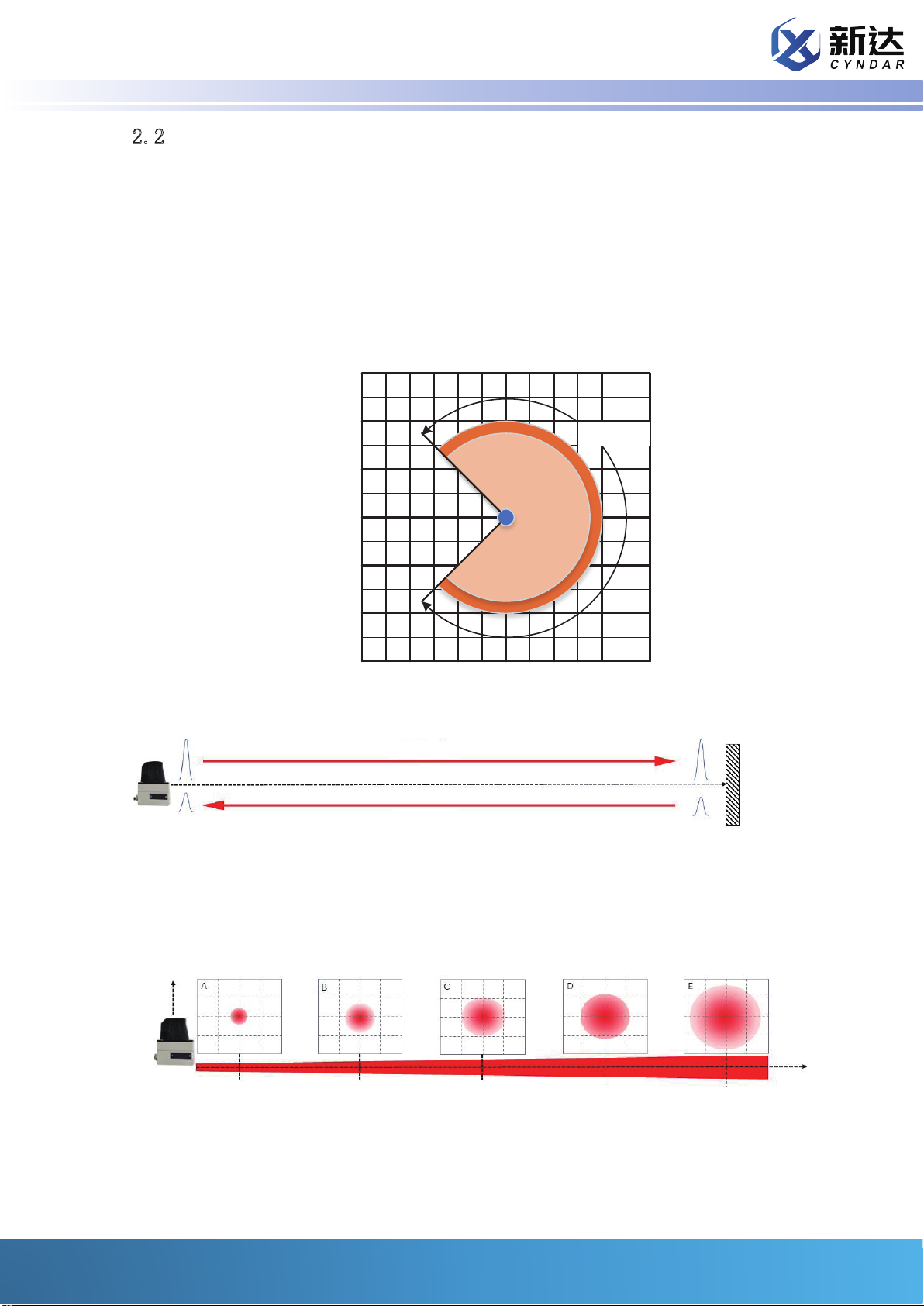
Within the measuring range, XD-TOF-25 can accurately measure the distance between the
object within the maximum range and the specified zero point. The measurement value
includes ranging error; in the process of continuous use, the measurement error at the same
detection distance presents a normal distribution. The following table gives the measurement
error of the statistical result at different detection distances and its standard deviation (specific
error And measurement).
Table 2-3 Ranging error within different detection distances
Ranging range
Ranging error
Standard deviation
of error distribution
The output range of XD-TOF-25 is 50mm-25000mm (the actual output is hexadecimal ASCII code,
1mm corresponds to 1h, ASCII code 30 30 30 31, 25000mm corresponds to 61A8h, ASCII code is 36
32 40 38, the specific format and details please (Refer to the section on data communication in
Section 4 Device Connection). For the ranging interval of 1-25000mm, our class has the following
division:
Table 2-4
Radar output Hex Significance
There are objects with too low reflectivity in this direction, the system cannot accurately identify
There are objects with too high reflectivity in this direction, the system cannot accurately identify
The diameter of the radar optics indicates that there is an object in the
observation direction, but the radar cannot clearly measure the
distance. Appeared in extremely special occasions, this option is to
avoid some physical conditions that we cannot understand that cause
the radar to fail to give accurate range values.
There is a certain fluctuating distance, with a maximum test relative
error of 5%. (Refer to test report)
Stable ranging distance, for normal reflectivity objects no more than
3cm ranging error

Sensing the world ·Leading the change
10
2.5
Area alarm
Within the measurement range, XD-TOF-25 integrates two different area alarm methods.
Method one:
Set through the client application TCPClient of XD-TOF-25; users can link with radar through
TCPClient and set any polygonal alarm area. When foreign objects invade the alarm area, TCP-
Client will flash the red icon and trigger an alarm bell.
Figure 2-9
TCPClient can set the alarm threshold, that is, the number of intrusion points allowed in the
alarm area. When the value is set to 0, any object that enters the area will trigger an alarm.
Method two:
Set the alarm area through the network TCP/IP protocol, and realize the external area alarm
through the digital I/O pin of the device. The digital I/O pin voltage is the same as the external
power supply voltage; when there are no abnormal objects in the alarm area, the digital I/O level is
lowered, and when foreign objects invade the alarm area, the digital I/O level is raised.
The protocol for setting the alarm area by TCP/IP is shown in 4.2 STEP13.

Sensing the world ·Leading the change
11
3
Equipment appearance
The overall dimensions and overall installation diagram are as follows. Unmarked units default to millimeters.
Figure 6 Overall installation effect

Sensing the world ·Leading the change
12
As shown in the figure, the front of the device is the status indicator, the horizontal center line is
the plane where the laser scanning optical axis is located, and the laser is emitted through the
infrared protective cover. Please pay attention to the maintenance of the protective cover during
use. Once the infrared transmission shield is seriously polluted and affects the realization of the
device function, please consider replacing the new infrared transmission shield. There are four
screw holes for installation and positioning at the bottom and the rear. You can complete the
scanning of the plane you need by fixing in different positions according to actual needs.
There are four interfaces below. The first picture shows the two necessary connection ports. For
the sake of safety protection level, we have equipped the four interfaces with protective caps
Of the four interfaces, two are more commonly used. The first one on the left is a power inter-
face, which is connected to a DC power supply of 12-30V (typical value is 24V); the first one is a
network port connection, and the initial function supports direct output of point cloud data
showing detectable objects in a 270° two-dimensional plane, You can convert the space target
distance information output by the device into the information you need according to actual
needs. At the same time, two other interfaces are reserved for your choice. You can view the
detailed description of the two interfaces in the "Device Connection" section.

Sensing the world ·Leading the change 13
4
4.1
The main view of the plane where the two interfaces are located is as follows:
Device connection
Main interface
Figure 7 Device external interface
The two interfaces from left to right are: network interface, I/O interface, data interface
and power interface. More detailed information is listed in the table below.

Sensing the world ·Leading the change 14
1
23
4
1 RX+
2 RX-
3 TX+
4 TX-
1
2
4
3
5
1 DR
2 RS232R
3 RS232T
4 GND
5 VCC
4.2
In order to complete the connection of the device and output the distance information
Adapted power cord and network cable.
Terminal equipped with TCP/IP protocol.
Interface
Net-
work
port
Power
supply
and I/O
inter-
face
Icon Pin Signal Features
Receiver
Receiver
Transmitter
Transmitter
Area alarm output (brown)
232 receive (white)
232 send (blue)
Power ground (black)
Positive power supply (gray)
Device connection and communication
of the target object in the scanning area to facilitate the conversion of subsequent
information, at least the following accessories are required:
9-30V DC power supply (typical value is 24V)
XD-TOF-25 lidar sensor
The device connection and the output of the target distance information in the detection
range will follow the following main steps (we have attached simple routines to help you
conduct quick and easy communication development. All routines do not include the
specific processing of data, excluding header files , Define, clear and other operations,
you need to design according to the actual situation).
STEP1: Place the XD-TOF-25 lidar sensor in a suitable position so that it can scan the area you
need.

Sensing the world ·Leading the change 15
STEPA4: Connect the network cable and set the relevant parameters of the client, refer to Table 4-2
IP 192.168.1.111
255.255.255.0
192.168.1.1
2111
TcpClient tcpClient = new TcpClient();
_tcpClient = tcpClient;
string ip = 192.169.1.111; //
int port = 2111; //
tcpClient.Connect(ip, port);
You can prefer the basic information setting of XD-TOF-25 series network through commands.
<STX>sWN{SPC}EIIpAddr{SPC}C0{SPC}A8{SPC}00{SPC}02<ETX>
02 73 57 4E 20 45 49 49 70 41 64 64 72 20 43 30 20 41 38 20
30 30 20 30 32 03
<STX> 02
sWN 73 57 4E
20
EIIpAddr 45 49 49 70 41 64 64 72
20
43 30
20
XD-TOF-25
STEPA2: The connection of the main interface. Network port connection: Use the appropriate
network cable to complete the connection to the TCP terminal of the protocol terminal through
TCPclient; use the appropriate power cable to complete the connection between the XD-TOF-25
lidar sensor and a suitable DC power supply.
STEPA3: DC power supply output power supply. At this time, the status display on the front of the
device lights up. When the green OK display light is on, the XD-TOF-25 lidar sensor starts to scan
within the scanned area.
Table 4-2 Basic information of device network connection
Subnet mask
Gateway
Port
(Routine 1) Connect with the device
Radar ip
Radar port
Set the IP command to: (set to 192.168.0.2)
Instruction
Actual sending
instruction (Hex)
Header
Data content
Space(SPC)
Space(SPC)
C0h (hexadecimal,
corresponding to 192)
Space(SPC)

Sensing the world ·Leading the change 16
41 38
20
30 30
20
30 32
<ETX> 03
<STX>sWN{SPC}Elgate{SPC}C0{SPC}A8{SPC}00{SPC}01<ETX>
02 73 57 4E 20 45 49 67 61 74 65 20 43 30 20 41 38 20 30 30
20 30 31 03
<STX> 02
sWN 73 57 4E
20
Elgate 45 49 67 61 74 65
20
43 30
20
41 38
20
30 30
20
30 31
<ETX> 03
Footer
The command to set the gateway is: (set to 192.168.0.1)
Instruction
Actual sending
instruction (Hex)
Header
Data content
Space(SPC)
Space(SPC)
Space(SPC)
Space(SPC)
Space(SPC)
C0h (hexadecimal,
corresponding to
192)
A8h (hexadecimal,
corresponding to
168)
00h (two-byte hexa-
decimal, correspond-
ing to 0)
01h (two-byte hexa-
decimal, correspond-
ing to 2)
Footer
A8h (hexadecimal,
corresponding to
168)
Space(SPC)
Space(SPC)
00h (two-byte hexa-
decimal, correspond-
ing to 0)
02h (two-byte hexa-
decimal, correspond-
ing to 2)
The command to set the subnet mask is: (set to 255.255.254.0)

Sensing the world ·Leading the change 17
<STX>sWN{SPC}EImask{SPC} FF{SPC}FF{SPC}FE{SPC}00<ETX>
02 73 57 4E 20 45 49 6D 61 73 6B 20 46 46 20 46 46 20 46 45
2030 30 03
<STX> 02
sWN 73 57 4E
20
EImask 45 49 6D 61 73 6B
20
46 46
20
46 46
20
46 45
20
30 30
<ETX> 03
STEP5:Log in to the device as a client sending commands
02
Refer to specific instruction content or data including content
03
<STX>sMN(SPC)SetAccessMode(SPC)03(SPC)F4724744<ETX>
Header
Data content
Actual sending
instruction (Hex)
Instruction
Footer
Space(SPC)
Space(SPC)
Space(SPC)
Space(SPC)
Space(SPC)
FFh (two-byte hexadec-
imal, corresponding to
255)
FFh (two-byte hexadeci-
mal, corresponding to
255)
FEh (two-byte hexadec-
imal, corresponding to
254)
00h (two-byte hexadeci-
mal, corresponding to 0)
Before officially starting communication, the communication format of XD-TOF-25 is
first introduced. The communication method of XD-TOF-25 is composed of hexadeci-
mal byte ASCII codes, and its formats include:
Table 4-3 Communication data packet format
Packet format
Start header: <STX>
Packet content
End trailer: <ETX>
Hexadecimal ASI code
Command name Signs and status Data (populated as appropriate) Signs and status
The application requests to log in to the client to log in to the radar communication (if this process is not
performed or the login password is incorrect, the radar will refuse to execute all commands related to
modifying the configuration). The radar login password defaults to F4724744 at the factory. The login
password can be based on the instructions Modified, but this function is not open for the time being.
The command to log in to the device is:
Instruction

Sensing the world ·Leading the change 18
02 73 4D 4E 20 53 65 74 41 63 63 65 73 73 4D 6F 64 65 20 30
3320 46 34 37 32 34 37 34 34 03
<STX> 02
sMN 73 4D 4E
20
SetAccessMode 53 65 74 41 63 63 65 73 73 4D 6F 64 65
20
30 33
20
46 34 37 32 34 37 34 34
<ETX> 03
If the command is successfully sent and the login is successful, you will receive the following feedback from the radar:
<STX>sAN(SPC)SetAccessMode(SPC)1<ETX>
02 73 41 4E 20 53 65 74 41 63 63 65 73 73 4D 6F 64 65 20 31 03
If the login command fails to be sent successfully, you will receive the following feedback:
<STX>sAN(SPC)SetAccessMode(SPC)0<ETX>
02 73 41 4E 20 53 65 74 41 63 63 65 73 73 4D 6F 64 65 20 30 03
byte[] loginlidar ={ 0x02, 0x73, 0x4D, 0x4E, 0x20, 0x53, 0x65, 0x74, 0x41, 0x63, 0x63, 0x65, 0x73,
0x73, 0x4D, 0x6F, 0x64, 0x65, 0x20, 0x30, 0x33, 0x20, 0x46, 0x34, 0x37, 0x32, 0x34, 0x37, 0x34,
0x34, 0x03 }; //Radar login instruction
clientStream.Write(loginlidar, 0, loginlidar.Length);//Send login instruction to radar
if (clientStream.CanRead)
{
byte[] loginanswer = new byte[1024]; //Open up cache
StringBuilder myCompleteMessage = new StringBuilder(); //Receive result variable
int numberOfBytesRead = 0;
do
{
numberofBytesRead = clientStream.Read(loginanswer, 0, loginanswer.Length);
//
myCompleteMessage.AppendFormat("{0}",Encoding.ASCII.GetString(myReadBuffer, 0,
numberOfBytesRead));
//Write all the information stack read by the network port to the receiving result variable
Header
Actual sending
instruction (Hex)
Data content
Footer
Space(SPC)
Space(SPC)
Space(SPC)
03 (Client login
status bit)
F4724744 (Client
login password)
(Routine 2) Log in to the device
Read TCPIP communication receive buffer

Sensing the world ·Leading the change 19
}
while (clientStream.DataAvailable); //If the data does not arrive, the loop is received
string result = myCompleteMessage.ToString();
string[] split = result.Split(new char[] { ' ' });//
loginresult.Text = split[3];//
STEP6:Read device name (can be omitted)
The application can ask for the radar device name::
<STX>sRN{SPC}LocationName<ETX>
02 73 52 4E 20 4C 6F 63 61 74 69 6F 6E 4E 61 6D 65 03
<STX> 02
sRN 73 52 4E
20
LocationName 4C 6F 63 61 74 69 6F 6E 4E 61 6D 65
<ETX> 03
<STX>sRA{SPC}LocationName{SPC}D{SPC}FocusRayLidar<ETX>
02 73 52 41 20 4C 6F 63 61 74 69 6F 6E 4E 61 6D 65 20 31 33 20 46 6F 63
75 73 72 61 79 4C 69 64 61 72 03
byte[] devicename = { 0x02, 0x73, 0x52, 0x4E, 0x20, 0x4C, 0x6F, 0x63, 0x61, 0x74, 0x69, 0x6F,
0x6E, 0x4E, 0x61, 0x6D, 0x65, 0x03 }; //Radar interrogation equipment name
clientStream.Write(devicename, 0, devicename.Length);//Send login instruction to radar
if (clientStream.CanRead)
{
byte[] nameanswer = new byte[1024]; //Open up cache
StringBuilder myCompleteMessage = new StringBuilder(); //Receive result variable
int numberOfBytesRead = 0;
do
{
numberofBytesRead = clientStream.Read(nameanswer, 0, nameanswer.Length);
//Read TCPIP communication receive buffer
You can continue to operate the acceptance information in myCompleteMessage to determine further operations. The
following continues to extract key instruction information, which may contain ETX, STX, you need to further elaborate
processing
Divide the received character string into N character string arrays with spaces.
The third part is the device login result information +ETX, the first byte is the login result information
:
::
Instruction
Header
Actual sending
instruction (Hex)
Data content
Footer
Space(SPC)
If the command is successfully sent, you will receive the following feedback
from the radar (the initial name of the radar is named FocusRayLidar):
(Routine 3) Read the device name
Table of contents
Popular Accessories manuals by other brands

Vega
Vega VEGACAP 63 operating instructions

Master
Master BCF 230RB User and Maintenance Book

XD COLLECTION
XD COLLECTION P322.22 Series manual

Avery Weigh-Tronix
Avery Weigh-Tronix ZM401 Service manual

PCB Piezotronics
PCB Piezotronics M261A01 Installation and operating manual

Micro Motion
Micro Motion CMF Series instruction manual