Cyrus MR3 User manual

UserInstructions
CyrusMR3

MUTE
-+
-+
MUTE
1
2
3
X-pander
1
MUTE LOCK
23CD TU
MR3
L
R
MADE IN ENGLAND
CD TU CD TU Z1 Z2 Z3
OUTPUT
INPUT
Z1 R-CH Z1 L-CH
AERIAL
MC-BUS
OUT
IN
PRECISION
ELECTRONIC
INSTRUMENT
CAUTION:REPLACE WITH
SAME TYPE FUSE.
ATTENTION: UTILISER UN
FUSIBLE DE RECHANGE DE
MEME TYPE
FUSE: T1A/250V
230V-50/60Hz @ 200W
MUTE
-+
MUTE
1
2
3
X-pander
MUTE
-+
MUTE
1
2
3
X-pander
Zone 2 Zone 2
Zone 3 Zone 3
Zone 1
Zone 1
FM7 FM7
CD Player CD Player
Amplifier
TU
TU TUZ2 Z2
Z3 Z3
CD
CD CD
Z1 R-CH Z1 R-CHZ1 L-CH Z1 L-CH
Zone 3 Amp Zone 3 Amp
Zone 2 Amp Zone 2 Amp
Fig 3
Fig 1 Fig 2
Fig 4 Fig 5
Cyrus MR3
a
a
1)
i
h
a
b
bc
d
e
f
g
b
c
c
d
d
efghi 1)
1!1@1#1$
1) i h g f
e

IN
IN
OUT
OUT
Power
Pre
Fig.7a Fig.8a
Fig.8b
Fig.9a
Fig.9b
Fig.9c
Fig.9dFig.7b
Cyrus MR3
Cyrus III
IN IN
ININ
IN IN
ININ
IN IN
ININ
IN
IN IN
ININ
OUT OUT
OUTOUT
OUT OUT
OUTOUT
OUT OUT
OUTOUT
OUT
OUT OUT
OUTOUT
Zone 1 Zone 1
Zone 1Zone 1
Zone 2 Zone 2
Zone 2Zone 2
Zone 3 Zone 3
Zone 3Zone 3
CD Player CD Player
CD PlayerCD Player
MR3 MR3
MR3MR3
FM7 FM7
FM7FM7
Power Power
PowerPower
Cyrus IIIi
XPA XPA
XPAXPA
Fig.6a
Fig.6b
Fig.6c
Fig.6d
IN
IN
OUT
OUT
Power
aCa7

Cyrus MR3 User Instructions
1
GB
GB
IMPORTANT! Read before operating this equipment!
WARNING: To reduce the risk of electrical shock do not remove any unit covers
or panels. There are no user serviceable parts in this product.
WARNING: To reduce the risk of electric shock, do not expose this equipment to
rain or moisture.
HEED WARNINGS: All warnings on the product and in the operating
instructions should be adhered to.
READ ALL THE INSTRUCTIONS: All the safety and operating instructions
should be read before the product is operated.
RETAIN INSTRUCTIONS: The safety and operating instructions should be
retained for future reference.
FOLLOW INSTRUCTIONS: All operating and use instructions should be
followed.
CLEANING: Unplug this product from the mains before cleaning. Do not use
liquid or aerosol cleaners. Use a damp cloth for cleaning.
WATER AND MOISTURE: Do not use this product near water - for example,
near a bath tub, wash bowl, kitchen sink, or laundry tub, in a wet basement; or
near a swimming pool and the like.
HEAT: The product should be situated away from heat sources such as
radiators, stoves, or any other products (including amplifiers) that produce heat.
VENTILATION: Slots and openings in the cabinet are provided for ventilation, to
ensure reliable operation of the product and to protect it from overheating and
these openings must not be blocked or covered. The openings should never be
blocked by placing the product on a bed, sofa, rug or similar surface. This
product should not be placed in a built-in installation such as a bookcase or rack
unless proper ventilation is provided or the manufacturer's instructions have been
adhered to.
OBJECT OR LIQUID ENTRY: Never push objects of any kind into this product
through openings as they may touch dangerous voltage points or short-out parts
that could result in a fire or electric shock.
ACCESSORIES: Do not place this product on an unstable cart, stand, tripod,
bracket, or table. The product may fall, causing serious injury to a child or adult,
and serious damage to the product. Use only with a cart, stand, tripod, bracket or
table recommended by the manufacturer, or sold with the product. Any mounting
of the product should follow the manufacturer's instructions, and should use a
mounting accessory recommended by the manufacturer.
ATTACHMENTS: Do not use attachments not recommended by the product
manufacturer as they may cause hazards.
POWER SOURCES: This product should be operated only from the type of
power source indicated on the marking label. If you are not sure of the type of
power supply to your home, consult your product dealer or local power company.
For products intended to operate from battery power, or other sources, refer to
the operating instructions.
OVERLOADING: Never overload wall outlets, extension cords, or integral
convenience receptacles. This can result in an increased risk of fire or electric
shock.
POWER CORD PROTECTION: Power supply cords should be routed so that
they are not likely to be walked on or pinched by items placed upon or against
them, paying particular attention to cords at plugs, convenience receptacles, and
the point where they exit from the product.
LIGHTNING: For added protection for this product during a lightning storm, or
when it is left unattended or unused for long periods of time, unplug it from the
wall outlet and disconnect the antenna or cable system. This will prevent
damage to the product due to lightning and power-line surges.
CAUTION! POLARISED CONNECTOR (CANADA and USA):
To prevent electrical shock, match wide blade of plug to wide slot, fully insert.
Do not alter or remove this plug if it does not fit your mains power socket. Have a
suitable socket installed by a competent electrician.
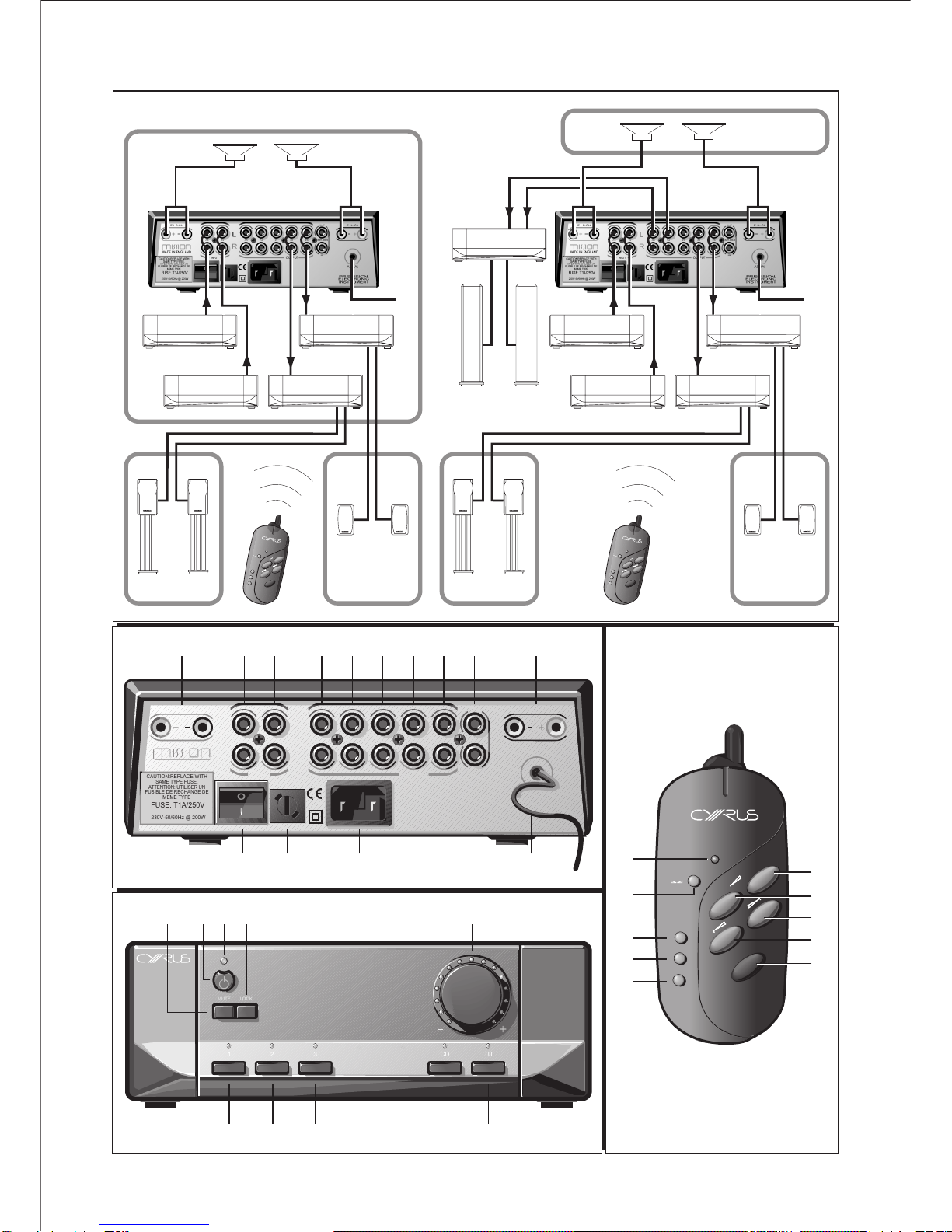
POWER SUPPLY:
The moulded IEC connector of the AC cord supplied plugs into the power
inlet r on the rear of the unit.
The mains fuse sis on the rear panel next to the power switch. It must
only be replaced as follows:
U.K. / Europe 230V T1A 20mm
N. America / Far East - 115V T2A 20mm
The mains supply requirement for your Cyrus MR3 is marked on a label
on the rear panel. Before connecting, check that this voltage is the same
as your mains supply.
230V Products: Voltage Range 220V-240V
115V Products: Voltage Range 110V-120V
If you move to an area with a different mains voltage, contact your local
Cyrus distributor to have your product converted.
NOTE FOR UK CUSTOMERS:
The Cyrus MR3 is supplied with a power cable terminated by a fused 13A mains
plug. This plug should not be removed but if it is removed, dispose of it safely
and do not re-use it. To connect a new 13A plug, proceed as follows: Connect
the brown wire to the terminal marked L or coloured red. Connect the blue wire to
the terminal marked N or coloured black. The internal plug fuse should be 5A.
SERVICING:
Do not attempt to service this product yourself as opening or removing covers
may expose you to dangerous voltage or other hazards. Refer all servicing to
qualified service personnel.
CONDITIONS REQUIRING SERVICE: Unplug this product from the wall outlet
and refer servicing to qualified service personnel when:
•When the power supply cord or plug is damaged.
•If liquid has been spilled, or objects have fallen into the product.
•If the product has been exposed to rain or water.
•If the product has been dropped or damaged in any way.
•If the product does not operate normally by following the operating
instructions. (Adjust only those controls that are covered by the
operating instructions. Improper adjustment of other controls may result
in damage requiring extensive work by a qualified technician to restore
the product to its normal operation).
•When the product exhibits a distinct change in performance.
REPLACEMENT PARTS: When replacement parts are required, be sure the
service technician has used replacements specified by the manufacturer or have
the same characteristics as the original part. Unauthorised substitutions may
result in fire, electric shock, or other hazards.
SAFETY CHECK:Upon completion of any service or repairs to this product, ask
the service technician to perform safety checks to determine that the product is in
proper operating condition.
MOVING THE PRODUCT: A product and cart combination
should be moved with care. Sudden stops, excessive force,
and uneven surfaces may cause the product and cart to
overturn.
CAUTION: The exclamation mark is to draw your attention
to important instructions and safety procedures in this
manual.
ATTENTION: The lightning flash warns you of the risk of
electrical shock presented by components inside this
p
roduct. Unauthorised
p
ersonnel must not o
p
en this unit.

User Instructions Cyrus MR3
2GB
GB
Welcome to the world of Cyrus!
Congratulations on your choice of Cyrus Hi-fi products. Our state-of-the-art
design technology and outstanding quality of manufacture has won countless
awards around the world. We are confident that you will derive great pleasure
from owning a product from one of the most recognised and respected
manufacturers of hi-fi equipment.
Please read these instructions carefully before commencing installation. They
provide full guidance to help you install your Cyrus MR3 safely and correctly.
Preparations for Installation
Before installing the Cyrus MR3 check that the following items are included in
the accessory box.
•Warranty Card (with instruction manual)
•AC Mains Cable
•Remote Control Handset
•2 AAA Batteries
•4 Loudspeaker plugs
•2 MC-Bus phono cables
After removing these items, please retain the packaging.
Install the Cyrus MR3 in a well ventilated location away from sources of high
temperature, dust or humidity. Never stand the MR3 under another unit or on
any surface likely to hamper its cooling or ventilation.
Choosing equipment to partner the MR3
All Cyrus CD players and the FM7 tuner are suitable as sources for the MR3.
All Cyrus power amplifiers are suitable for MR3 installations. In most cases
the XPA will be the preferred choice due to its ability to switch on
automatically when music is present.
The MR3 will also fully integrate with an existing Cyrus system including
Cyrus IIIi or Cyrus aCA7 amplification. For systems based around the Cyrus
III or Cyrus Pre amplifiers, certain considerations must be made when wiring
in MC-Bus control. See ‘MC-Bus connections’ section for more detail.
Installation (Refer to Fig.3)
Key to the rear panel drawing
1. Zone 1 LS Output (R.Ch) 8. Line Output - Zone 3
2. CD Input 9. MC-BUS Connection
3. Tuner Input 10. Zone 1 LS Output (L.Ch)
4. CD Output 11. Remote Control antenna
5. TU Output 12. IEC Mains Connector
6. Line Output - Zone 1 13. AC Power Fuse
7. Line Output - Zone 2 14. AC Power Switch
Positioning the Remote Antenna
Position the antenna 1! straight out behind the unit, or facing vertically upward
or sideways. Keep the antenna (especially the tip) as far away from metal
surfaces and cables as possible.
Do NOT wrap the antenna under the unit.
Do NOT shorten or extend the antenna cable.
When used in a HARK or other equipment rack, the Cyrus MR3 should be
placed on the top shelf to give maximum range.
Connecting inputs to the MR3 (Refer to Fig.1)
Using a suitable phono interconnect:
1. Connect a CD Player to the CD input bon the rear panel
2. Connect a tuner to the TU input con the rear panel
Connecting a CD player and Tuner through the
MR3 to an Existing Cyrus system (Refer to Fig.2)
If the MR3 is to be added to an existing system, the CD and tuner outputs
must be connected from the MR3 to the main system amplifier as follows-
1. Connect the CD input of the amplifier to the CD OUT socket d.
2. Connect the Tuner input of the amplifier to the TU OUT socket e.
This enables a single CD player and Tuner to be shared by the MR3 and the
main system.
Connecting speakers directly to Zone 1 outputs
The MR3 includes an internal power amplifier for Zone 1. The Zone 1
speakers may therefore be connected directly to the MR3 power amplifier if
preferred as follows-
1. Connect the cables to the speakers and run them back to the rear panel
of the MR3. Make sure that the left and right cables can be identified,
also the wires from the red (+) speaker terminals. Most speaker cables
will have a stripe or mark to show the (+) terminal.
2. Strip 10mm of insulation from the ends of the speaker cables.
3. Screw the cables securely into the speaker plugs. Make sure that the
red plugs are connected to the wires from the red (+) speaker terminals.
4. Plug the cables into the Zone 1 speaker sockets a,pof the MR3.
Connecting power amplifiers (Zones 1,2,3)
External power amplifiers are necessary for Zones 2 and 3 and optional to
increase performance in Zone 1.
These power amplifiers are most easily located near to the main MR3 unit
with long speaker cable to the extension zones. If preferred, long
interconnects can be run to remote power amplifiers which are located in the
remote zone, then short speaker cables run locally to the speakers. For this
type of installation, special long input interconnects are necessary and the
installation should be made by a specialist dealer.
To connect the power amplifiers, proceed as follows-
1. Connect a stereo phono interconnect between each Zone output
f,g,hand a power amplifier input.
2. Connect the cables to the speakers and run them back to the rear panel
of the power amplifier. Make sure that the left and right cables can be
identified, also the wires from the red (+) speaker terminals. Most
speaker cables will have a stripe or mark to show the (+) terminal.
3. Connect the speaker cables to the speaker output terminals of the
power amplifier, observing polarity and channel orientation.
MC-BUS CONNECTIONS (See Fig.6)
NOTE:- MC-Bus connections must be made to communicate remote
commands from the MR3 to the CD player and FM7.
An MC-Bus loop is established by connecting single phono cables from the
MC-Bus output of each unit to the MC-Bus input of another in a chain.
Complete the loop by returning the MC-Bus output of the final component to
the MC-Bus input of the first.
Fig.6a shows an MC-BUS system loop of MR3, Cyrus CD player, FM7 and a
Cyrus Power (where used). The Standby control of the MR3 will switch on or
off all connected Cyrus units.
Fig.6b shows the MC-Bus connections extended to include the ‘main system’
Cyrus amplifier, Cyrus IIIi or Cyrus aCA7.
Figs.6c/d show systems with Cyrus III or Cyrus Pre amplifiers. The MC-Bus
connections of these amplifiers cannot be wired into the same MC-Bus loop
as the MR3 system.

Cyrus MR3 User Instructions
3
GB
GB
Operating the MR3 from the front panel
Key to the front panel drawing (Refer to Fig.4)
1. Mute key 6. Tuner select
2. Standby key 7. CD select
3. Standby light 8. Zone 3 select
4. Lock 9. Zone 2 select
5. Level Control 10. Zone 1 select
Power Control (Refer to Fig.4)
The mains power switch tis located on the rear panel. This switch should
normally be left on. If the unit is left unattended for long periods it should be
switched off or the product disconnected from the mains power supply.
When power is applied, the STANDBY key bis used for power control. The
Standby light cshows green when the MR3 is operating and glows red when
in standby mode.
When the MR3 is switched on from Standby, all Zones are set to MUTE (zero
volume level). A red light at the extreme left of the LEVEL control eindicates
MUTE. (See Fig.7b)
Selecting a Zone from the front panel
Press a Zone selector key h- p.
The selected zone is now operational. A red light above the Zone key
indicates that the Zone is under front panel control.
NOTE:- If a zone selector is pressed while the MR3 is set to Standby, the unit
will switch on.
Muting and Unmuting a Zone
1. Press the MUTE key a............................................ The Zone will mute.
2. Press the MUTE key again or adjust level.............. The Zone will restore.
Selecting an Input
Press the CD key gto select the CD input
Press the TU key fto select the tuner input.
Level Control (Refer Fig.7a)
Use the LEVEL control eto set the volume in the selected Zone.
The Level control of the MR3 adjusts volume and balance. A light ring around
the knob indicates the level. When the volume is at minimum the first indicator
on the light ring will be RED. As the volume increases, a GREEN light moves
clockwise around the ring.
Balance is adjusted using the remote handset. (See Page 4)
To set the maximum level in a Zone: (see Fig.8)
The maximum level in any Zone can be set from the front panel. This is useful
where low powered speakers are in use or where high volume levels could
cause nuisance.
1. Select a Zone and hold the Zone key down.
The level display changes to a continuous light ring. ............................ (Fig.8a)
2. Keep holding the zone key and adjust the volume to the required level.
3. Release the Zone key.
The display will now show a single light. This indicates the maximum
allowable volume in the selected Zone...................................................(Fig.8b)
When the volume in this Zone is adjusted the level control will function
normally until the maximum preset level is reached. When this level is
reached the light on the level control will flash .
Lock – Cyrus CD Players and FM7 Tuner Only
When using a multi room system, the same source is often playing in more
than one Zone. To avoid possible difficulties, a Cyrus CD Player or FM7 can
be functionally ‘locked’ from the front panel of the MR3.
When the system is locked the handset will not be able to change tracks on a
Cyrus CD player or alter preset stations on the FM7. Other handset functions
are unaffected.
1. Press the LOCK key d
The lights above the CD and TU keys change from red to yellow.
Press LOCK to restore normal operation.

User Instructions Cyrus MR3
4GB
GB
THE CYRUS X-PANDER RF HANDSET
Key to the X-pander drawing (Fig.5):
1. Balance key 6. Track / Preset Down
2. Indicator light 7. Mute / Standby key
3. Volume +(Up) key 8. Zone 1 select key
4. Volume -(Down) key 9. Zone 2 select key
5. Track / Preset Up key 10 Zone 3 select key
Setting up RF channels on the MR3
To avoid any interaction between neighbouring MR3 installations, the MR3
offers a choice of four RF channels for remote commands.
As delivered, the MR3 main unit is set to Channel Zero. This will not normally
need alteration. At installation and when the batteries are replaced, the X-
pander remote control must also be set to channel 0 to ensure communication
between the two units..
Inserting the Batteries and setting RF channel 0 for
the X-pander remote control
CAUTION:- Inserting the batteries in the X-pander handset forms part of the
RF Channel setup procedure- avoid touching the handset buttons when
inserting the batteries.
1. Remove the battery compartment cover.
2. Hold the handset by the edges and insert the supplied AAA batteries
into the battery compartment. Observe polarity markings on the
batteries and battery compartment.
3. Replace the cover.
4. Press the mute key.
Changing the MR3 RF Channel setting
1. Switch the MR3 off at the rear panel power switch.
2. Wait 30 seconds for the internal memory to discharge.
3. Hold down the key shown in the list to select a new RF channel and
switch the power on.
Standby......................Select channel 0
Zone 1........................Select channel 1
Zone 2........................Select channel 2
Zone 3........................Select channel 3
4. The MR3 will run its set-up routine and the indicator above the key will
flash three times before the MR3 enters Standby mode. The RF
Channel is now reset.
Caution: If the RF Channel is changed at the MR3, the X-pander remote
control must also be changed to the same channel number. Failure to do this
will mean that the handset will not be able to communicate with the MR3 main
unit.
Changing the X-pander RF Channel setting
1. Remove the battery compartment cover.
2. Remove the batteries and wait two minutes for the internal memory to
discharge.
3. Hold the handset by the edges and insert the supplied AAA batteries
into the battery compartment. Observe polarity markings on the
batteries and battery compartment.
4. Replace the cover.
The first key pressed will now set the RF channel as follows-
Mute ...........................Select channel 0
Zone 1........................Select channel 1
Zone 2........................Select channel 2
Zone 3........................Select channel 3
The RF channel setting will now be stored by the remote control.
Handset Indications
The X-pander has two features to indicate normal functioning.
1. When a handset button is pressed, the Indicator light bflashes to show
that a command has been sent.
2. You will also hear a ‘beep’ from the speakers so that you know you are
in the correct Zone.
3. When the MR3 receives a command from a remote Zone, the indicator
on the front panel above the relevant Zone key will flash.
Selecting or Changing a Zone
Press once on the required Zone key h, i, p
If you are in the correct Zone you will hear a short beep.
If the system is in STANDBY, this operation will also bring the MR3
installation out of Standby mode.
Changing the Source
Press and hold down the appropriate Zone key h, i
, p
for about three
seconds. The source will change from CD to Tuner or vice versa.
You will hear a single beep followed by a double beep.
Volume Adjustment
Press the + key cto increase the volume level.
Press the - key dto reduce the volume level.
There is no beep with these operations.
Channel Balance Adjustment
1. Press the balance key aonce ................................................. Single Beep
2. Press the + key cto shift the balance to the right.
Press the - key dto shift the balance to the left.
3. Press the balance key aonce ................................................. Single Beep
The new balance setting is now stored.
NOTE:- The front panel display will change during balance setting (see Fig.9)
To reset the Channel Balance to ‘central’:
Press and hold the balance key adown for a few seconds
A single beep is followed by a double beep
Muting a Zone
Press the Mute key g...................................................................... Single Beep
The sound in your Zone is now muted.
To unmute a Zone:
Press the Mute key again or............................................................Single Beep
Press the + key c................................................................................. No Beep
The volume will restore at its original level prior to muting.
Setting the System to Standby
Press and hold the MUTE key gdown.
A single beep is followed by a double beep.
Remote Operation of Cyrus Source Components
When the MR3 is connected to Cyrus source units in an MC BUS loop,
remote operation of those sources is possible (See Page 4).
Cyrus dAD3, dAD1, dAD7 and Discmaster
•Press the next key eto go to the next track.......................... Single Beep
•Press the previous key ffor the previous track....................Single Beep
Pressing either key will start a dAD3 or dAD1 if it is not playing.
Cyrus FM7
•Press the next key efor the next station............................... Single Beep
•Press the previous key ffor the previous station.................Single Beep
Current FM7s are fully compatible. Earlier FM7s can be updated to use this
feature. (See Page 5 for details).
Note: Pressing the next or previous keys in LOCK mode will produce no
response, however you will hear a low beep.

Cyrus MR3 User Instructions
5
GB
GB
TROUBLESHOOTING GUIDE
If your MR3 is not operating properly, disconnect the power and carefully
check all connections using the notes in this handbook. If problems persist,
the checklists below may help.
If you are in any doubt, consult your dealer.
Remote control not working (front panel control OK)
Mismatch between RF channels of
handset and MR3
Check RF channel setting
Handset batteries flat Replace batteries
No Sound
MR3 switched off or in Standby Switch on
MR3 or handset set to incorrect
Zone
Select the correct Zone
Incorrect Input Selected Select correct input
System amplifiers are not powered Switch on all system amplifiers
Source not playing Operate source
No sound from one loudspeaker
BAL control at extreme limit Centralise Balance
Loudspeaker defective Check loudspeaker, replace fuses
Faulty Loudspeaker connection Check cables and connections
Volume of source changes without any command
A second MR3 is in use nearby Change RF channels
The volume will not go loud enough
Set the maximum Zone level setting higher
Handset not operational or partially operational
Handset set to the incorrect Zone Select the correct zone
Sound suddenly disappears
The system has been set to Standby from another zone
Mute has been selected from another zone
Next/Previous keys not working
The MR3 is set to LOCK mode Switch off LOCK
FM7 preset selection will not function from remote control
The FM7 may be an early production unit. An upgrade is available to add this
feature, see ‘software upgrades’ below.
Discmaster/dAD7 will not play start
See ‘software upgrades’ below.
Software upgrades for FM7, dAD7, Discmaster
Remote operation of Cyrus CD Players and Tuners is carried out via the
handset operating through the MC-BUS loop.
Cyrus FM7 Tuner
Units with serial numbers higher than those in the series listed below are fully
compatible.
UK ...............................HCU01231 EUROPE ...................HCS01027
TAIWAN ......................HCT00108 CANADA ...................HCC00127
Earlier FM7 units:
Software updates are available to add next/previous preset commands when
used with the MR3.
Cyrus dAD7, Discmaster:
Software updates are available to add the ‘autoplay’ command which will
initiate CD play when next/previous keys are selected from the X-pander.
Consult your Cyrus dealer for information and conversion costs for these
upgrades.
Cyrus dAD1, dAD3 and dAD3Q CD players
Are fully compatible and support the ‘autoplay’ command.
WARRANTY
Specifications
Power Supply
Voltage:....................................................... As plate on rear of unit
Power consumption .................................... (120W)
Safety Requirements .................................. EN 60065
EMC compliance......................................... EN55013 & EN55020
Enclosure
Dimensions (WxHxD).................................. 215 x 75 x 365mm
Weight......................................................... 4.6Kg
Material ....................................................... Die cast chassis
Audio Performance
Inputs
Input Sensitivity (all line inputs) .................. 200mV
Input Impedance ........................................ 33kΩ
Line Outputs
Output voltage (all line outputs) .................. 380mV
Output Impedance ...................................... 100Ω
Channel separation (stereo) ....................... >70dB
S/N ratio, 500mV i/p (max.vol. A Wtd.)....... 100dBr
THD+N, 500mV i/p (1kHz, -6dBFS)............ 0.004%
Zone 1 Power amplifier
Power output (1kHz//8Ω)............................ 32W
THD+N 32W (20kHz//8Ω) .......................... <0.06%
Frequency response (-3dB) ........................ 8Hz, 70kHz
Cyrus reserves the right to change all specifications without notice. E &OE
The warranty card enclosed should be completed by the Dealer and
the purchaser and returned to CYRUS or its Distributor within 8 days
of purchase. No Dealer or Distributor may vary the terms of this
warranty which is personal to the original Purchaser and is not
transferable.
Please retain the sales receipt as proof of purchase.
Warranty claims must wherever possible be made through the Dealer
from whom the equipment was purchased.
This warranty excludes:
•Damage caused through neglect, accident, misuse, wear and
tear, or through incorrect installation, adjustment or repair by
unauthorised personnel. Any unauthorised servicing will result in
loss of guarantee.
•Liability for damage or loss occurring in transit to or from the
purchaser.
•Consequential damage, loss or injury, arising from or in
conjunction with this equipment.
Equipment for attention under warranty should be consigned return
carriage paid. If returned equipment is found to comply with the
published specification, MISSION reserves the right to raise a charge.
The above conditions do not affect your statutory rights as a
consumer.
Table of contents
Other Cyrus Stereo System manuals