cytiva Monitor ALP-900 User manual

Table of Contents
1Introduction ........................................................................................................ 3
1.1 About this manual ......................................................................................................................................... 4
1.2 Important information ................................................................................................................................. 5
2 Safety instructions ............................................................................................. 7
3 Instrument description ...................................................................................... 8
3.1 Instrument ........................................................................................................................................................ 9
3.2 Modules ............................................................................................................................................................. 11
4 Installation .......................................................................................................... 14
4.1 Attaching the movable air sensor ........................................................................................................... 15
4.2 Calculate accumulated air ......................................................................................................................... 17
5 Maintenance ....................................................................................................... 18
5.1 Maintenance program ................................................................................................................................. 19
5.2 Cleaning ............................................................................................................................................................ 20
6 Troubleshooting ................................................................................................. 21
6.1 Before calling Cytiva support .................................................................................................................... 22
6.2 Troubleshooting guide ................................................................................................................................. 23
7 Reference information ....................................................................................... 26
7.1 Technical specifications .............................................................................................................................. 27
7.2 Health and Safety Declaration Form ...................................................................................................... 28
Index ........................................................................................................................... 30
Table of Contents
2 Monitor ALP-900 User Manual 29265903 AB

1 Introduction
About this chapter
This chapter contains important user information, descriptions of safety notices and
intended use of the ALP-900 (Air, Level, Pressure transmitter) monitor.
In this chapter
Section See page
1.1 About this manual 4
1.2 Important information 5
1 Introduction
Monitor ALP-900 User Manual 29265903 AB 3

1.1 About this manual
Purpose of this manual
The User Manual provides you with the information needed to operate and maintain
the ALP-900 monitor in a safe way. It does not provide information about the use of the
parent system that the monitor may be incorporated into.
Scope of this manual
The User Manual covers the ALP-900 monitor. The illustration below shows the
ALP-900 system.
Typographical conventions
Software items are identified in the text by bold italic text.
Hardware items are identified in the text by bold text.
In electronic format, references in italics are clickable hyperlinks.
1 Introduction
1.1 About this manual
4 Monitor ALP-900 User Manual 29265903 AB

1.2 Important information
Read this before operating the
product
All users must read the following documents in their entirety before installing,
operating or maintaining the product:
•this User Manual, 29265903
•the Operating Instructions manual of the parent system.
Always keep this User Manual and the Operating Instructions at hand when operating
the product.
Do not operate the product in any other way than described in the user documenta-
tion. If you do, you may be exposed to hazards that can lead to personal injury and you
may cause damage to the equipment.
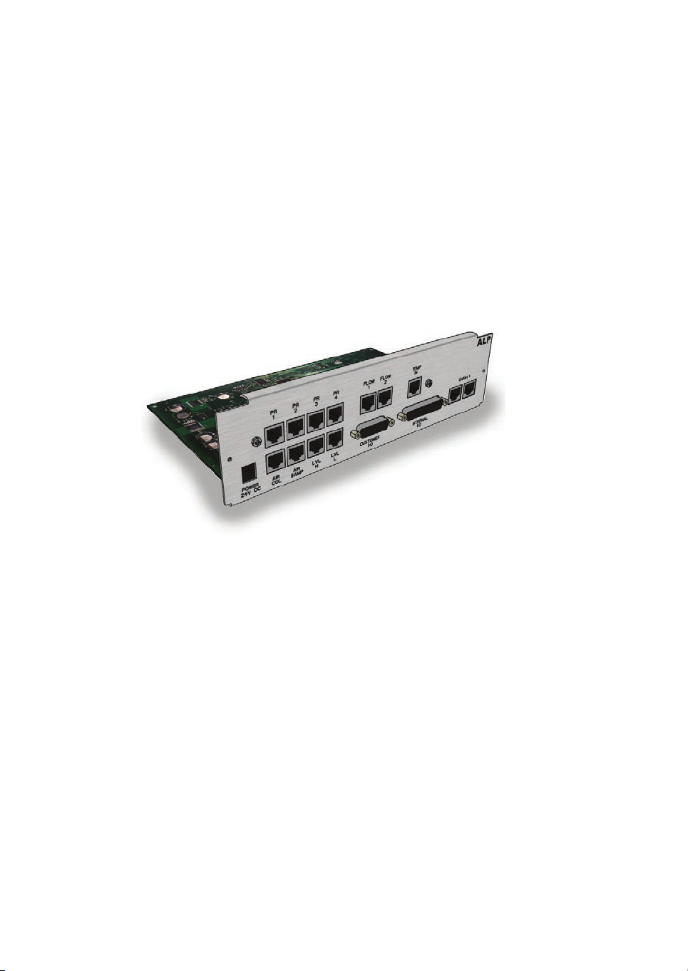
Intended use of the product
ALP-900 is a high precision multi-purpose monitor designed to detect air, measure and
supervise pressure and temperatures, handle level signals from the air trap and
internal and external I/O signals. It is used in ÄKTAprocess™, BioProcess™ and
UniFlux™ systems.
The instrument is delivered pre-installed in the parent system with all electrical
connections prepared inside the electronics cabinet. ALP-900 monitor has no user
interface for the operator, it is controlled entirely via the system control software.
Prerequisites
In order to operate ALP-900 in the way it is intended:
•The user should understand the concepts of liquid chromatography.
•The user must read and understand the Safety Instructions chapter in this manual
and in the Operating instructions manual of the parent system.
Safety notices
This user documentation contains safety notices (WARNING, CAUTION, and NOTICE)
concerning the safe use of the product. See definitions below.
1 Introduction
1.2 Important information
Monitor ALP-900 User Manual 29265903 AB 5

WARNING
WARNING indicates a hazardous situation which, if not avoided,
could result in death or serious injury. It is important not to proceed
until all stated conditions are met and clearly understood.
CAUTION
CAUTION indicates a hazardous situation which, if not avoided,
could result in minor or moderate injury. It is important not to
proceed until all stated conditions are met and clearly understood.
NOTICE
NOTICE indicates instructions that must be followed to avoid
damage to the product or other equipment.
Notes and tips
Note: A note is used to indicate information that is important for trouble-free and
optimal use of the product.
Tip: A tip contains useful information that can improve or optimize your proce-
dures.
1 Introduction
1.2 Important information
6 Monitor ALP-900 User Manual 29265903 AB

2 Safety instructions
About this chapter
This chapter describes safety precautions, labels and symbols that are attached to the
equipment.
Important
WARNING
Before installing, operating or maintaining the product, all
users must read and understand the entire contents of this
chapter to become aware of the hazards involved.
Safety precautions
Refer to the safety instructions described in the manual of the parent system.
Follow the instructions provided to avoid injury to the operator or other
personnel, damage to the product, or to other equipment in the area.
NOTICE
The ALP-900 safety module that monitors the pump/operating
pressure is a protection for the system and NOT the column.
2 Safety instructions
Monitor ALP-900 User Manual 29265903 AB 7

3.1 Instrument
Introduction
This section gives an overview of the ALP-900 monitor.
ALP-900 monitor
The ALP-900 monitor detects air, and measures and supervises pressure and tempera-
tures in ÄKTAprocess, BioProcess and UniFlux systems.
The ALP-900 module has air, pressure and temperature monitoring modules.
•The air module monitors signals from two air sensors.
•The pressure module monitors signals from up to four pressure sensors.
•The ALP-900 also monitors temperature in the electronics cabinet and the liquid
temperature in the system.
If any of the monitored parameters reaches a critical limit, the ALP-900 will shut down
the pumps independently of the system control software.
ALP-900 functionality
The following table describes examples of how ALP-900 functionality options may be
used in a parent system. The examples provided are for illustrative purposes only and
may vary according to the configuration of the individual system.
Parent system ALP-900 functionality
ÄKTAprocess •Air detection
•Pressure measurement and surveillance
•Temperature measurement and surveillance
UniFlux •Pressure measurement and surveillance
•Temperature measurement and surveillance
BioProcess •Pressure measurement and surveillance
3 Instrument description
3.1 Instrument
Monitor ALP-900 User Manual 29265903 AB 9

Illustration of ALP-900
The illustration below shows the ALP-900 monitor.
3 Instrument description
3.1 Instrument
10 Monitor ALP-900 User Manual 29265903 AB

3.2 Modules
Introduction
This section gives an overview of the modules of the ALP-900 monitor.
Illustration of connectors on ALP-900
The illustration below shows the locations and gives brief descriptions of the connec-
tors on ALP-900.
1
23
7
8
9
4
5
6
Part Function
1 Pressure sensor connector
2Flow meter connector (future option for BioProcess
systems)
3 Temperature sensor IN connector
4UniNet 1 connector
5Internal I/O connector
3 Instrument description
3.2 Modules
Monitor ALP-900 User Manual 29265903 AB 11

Part Function
6Customer I/O connector
7 Level sensor connector (LVL Hi and LVL Lo)
8 Air sensor connectors (AIR COL and AIR SAMP)
9 Power connector
Air sensors
ÄKTAprocess and BioProcess systems are equipped with two air sensors. ALP-900
monitors the signals from these air sensors.
1. The first sensor (AIR COL) is permanently installed before the column valve
block(s). The purpose of this sensor is to protect the column(s) from air in the liquid
flow. When the AIR COL is enabled (default) and air is detected, this sensor will set
the system to PAUSE and an error will be indicated. For more information, refer to
the manual of the parent system.
2. The second sensor (AIR SAMP) is movable and can be inserted after any inlet. A
typical application for this sensor is to indicate when a sample is finished. When the
movable sensor is not used it should be placed in a recessed holder in the system
frame, above the inlets. For more information, refer to Section 4.1 Attaching the
movable air sensor, on page 15.
Level sensors
ALP-900 monitors the signals from two capacitive level sensors (High and Low),
installed in the air trap. The signals from these sensors monitor the liquid level in the air
trap.
This function is not used when the parent system is ÄKTAprocess.
Pressure sensors
The ALP-900 monitor can register pressure signals from up to four pressure transmit-
ters. Two pressure sensors are mandatory for ÄKTAprocess and BioProcess systems.
•One pressure sensor is located before the air trap.
•One pressure sensor is located before the column 1 valve block.
If a sample pump is included in the parent system, a third pressure sensor is located
after the sample pump.
If a fourth sensor is included in the parent system, it is located after the column valve
blocks.
For ÄKTAprocess and BioProcess systems configured with pressure control valves
(PCV), pressure sensors are located before the pressure control valves. For systems
configured with two pumps, pressure sensors are located between the pumps and the
PCVs. These sensors are monitored by an additional ALP-900 monitor.
3 Instrument description
3.2 Modules
12 Monitor ALP-900 User Manual 29265903 AB

Temperature sensors
ALP-900 monitors the following two temperature signals:
•One signal monitors the temperature in the electronics cabinet. The temperature is
registered by a sensor that is mounted inside ALP-900. If the temperature in the
electronics cabinet exceeds 40°C a warning is sent to system control software.
•The second signal monitors the temperature in the process liquid by feedback from
the pre-column pH and conductivity monitor, pH/C-902, from the temperature
sensor in the conductivity cell CE-101.
Pressure and temperature
surveillance
A surveillance function will turn off the flow if the temperature and/or pressure exceeds
the limits for the tubing type and size in question. Refer to the manual of the parent
system for information about the pressure and temperature limits.
Note: For ÄKTAprocess and BioProcess: Maximum accepted system pressures
may only be set by Cytiva service engineers.
For other systems: Maximum accepted system pressure can also be set to
match the pressure rating on that system.
Customer I/O connections
An external 15-pin D-sub connector is available on ÄKTAprocess and BioProcess
systems, for programmable general purpose DC signals, both inbound and outbound.
The signals may be used for many different purposes, for example to control an
external valve and to receive state readings in return from the valve. Instrument read-
ings may be transmitted to general process control systems and external alarms can
be controlled.
Refer to the manual of the parent system for information about the location of the
customer I/O connector and mapping between the pins and signal types. For more
information about suitable applications and technical solutions, contact Cytiva
customer service.
3 Instrument description
3.2 Modules
Monitor ALP-900 User Manual 29265903 AB 13

4 Installation
About this chapter
The instrument is delivered pre-installed in the parent system with all electrical
connections prepared inside the electronics cabinet. The air and pressure sensors are
also mounted in the correct positions.
This chapter describes how to use the movable air sensor connected to the ALP-900. It
also describes how the ALP-900 calculates the volume of accumulated air.
In this chapter
Section See page
4.1 Attaching the movable air sensor 15
4.2 Calculate accumulated air 17
4 Installation
14 Monitor ALP-900 User Manual 29265903 AB

4.1 Attaching the movable air sensor
Introduction
This section describes how to use the movable air sensor. Refer to the manual of the
parent system for more information about the movable air sensor.
Requirements
To be able to detect air before it enters the system certain minimum tubing lengths are
required. The table below describes the specified tubing diameters, length and
maximum flows that are required for the AIR SAMP air sensor to function properly.
Tubing diameter (mm) Maximum flow rate
(L/hr)
Minimum tubing
lenght (m)
6.00 180 0.71
10.00 600 0.85
22.00 1800 0.53
Attaching the movable air sensor
Follow the instructions below to use the movable air sensor.
Step Action
1The movable air sensor may be optionally placed on any inlet.
2Place the movable air sensor (AIR SAMP) on a horizontal flow path (e.g. on
the inlet).
3Rotate the connector, so that it is vertical, as marked on the air sensor.
4 Installation
4.1 Attaching the movable air sensor
Monitor ALP-900 User Manual 29265903 AB 15

Step Action
Note:
The air sensor connector may face either upwards, downwards, left or right.
Downwards is recommended to minimize the risk for ingress of liquid into the
connector when disconnecting it. If the sensor is oriented in any other angle it
may not detect small bubbles properly.
4 Installation
4.1 Attaching the movable air sensor
16 Monitor ALP-900 User Manual 29265903 AB

4.2 Calculate accumulated air
Introduction
This section describes how to calculate the accumulated air volume that goes into the
column during a run.
Accumulated air
An approximation of the accumulated air volume that passes the air sensor before the
column can be calculated to keep track of how much air goes into the column during a
run.
The calculation of accumulated air is started when a new run is started and stopped
when the system is set to END. When the system is set to RUN again the accumulated
air is set to zero and a new accumulated air volume is calculated for this run.
4 Installation
4.2 Calculate accumulated air
Monitor ALP-900 User Manual 29265903 AB 17

5.1 Maintenance program
Periodic maintenance
Refer to the manual of the parent system for information about maintenance of the
ALP-900 monitor.
5 Maintenance
5.1 Maintenance program
Monitor ALP-900 User Manual 29265903 AB 19

5.2 Cleaning
Cleaning before planned
maintenance/service
To ensure the protection and safety of service personnel, all equipment and work areas
must be clean and free of any hazardous contaminants before a Service Engineer
starts maintenance work.
Please complete the checklist in the On Site Service Health and Safety Declaration
Form or the Health and Safety Declaration Form for Product Return or Servicing,
depending on whether the instrument is going to be serviced on site or returned for
service, respectively.
Copy the form you need from Section 7.2 Health and Safety Declaration Form, on page
28.
5 Maintenance
5.2 Cleaning
20 Monitor ALP-900 User Manual 29265903 AB
Table of contents
Other cytiva Transmitter manuals
Popular Transmitter manuals by other brands

Beyerdynamic
Beyerdynamic AD 808 operating instructions

Magnetek
Magnetek Flex VUE product manual

Honeywell
Honeywell PWTA40 Series installation instructions

Burkert
Burkert 8225 Operating instructions manual

RKI Instruments
RKI Instruments 65-2340RK Operator's manual

Xylem
Xylem MJK SuSix Installation and user manual