Brähler Systems INFRACOM ICen IV User manual
INFRACOM®
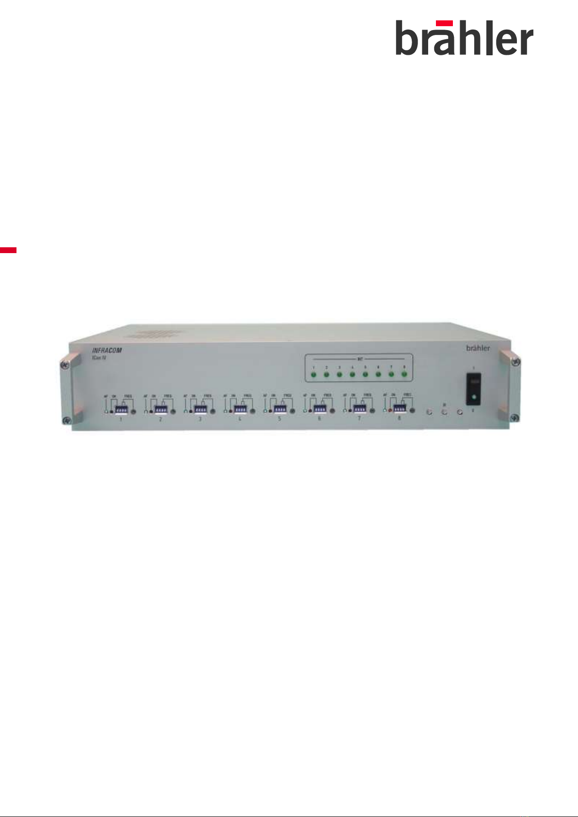
Compact Transmitter ICen IV
Operating instructions
Version 1.00

ICen IV
INFRACOM®
2Copyright by Brähler ICS
Printed in Germany
If you have questions about this manual please contact:
Brähler ICS Konferenztechnik
International Congress Service AG
P.O. Box 32 64
53627 Königswinter, Germany
Wahlfelder Mühle 3
53639 Königswinter, Germany
T +49 (0)2244 930-0
You will find further information about our products on the internet at:
www.braehler.com
© 2010
BRÄHLER ICS AG, Königswinter
All rights reserved, especially (also partly) the translation, reprint, reproduction through copying or
other similar methods.
BRÄHLER ICS reserves the right to make changes without notice.
INFRACOM® and DIGIMIC® are registered trademarks
Operating instructions INFRACOM, BGE-ICenIV.doc

INFRACOM® ICen IV
Copyright by Brähler ICS 3
! CAUTION !
DANGER OF ELECTRIC SHOCK
DO NOT OPEN DEVICES
Do not open housing with mains cable connected.
Maintenance operations may only be done by
qualified personnel.
Our equipment and installations have been built and tested according to the latest state of the art.
Under normal conditions, they do not require any special maintenance.
However, please be aware of the following:
secure and stable position of the installation
sufficient ventilation - never operate equipment near heat sources such as heating radiators
etc.
power connection - install all power cables to avoid damaging
connecting cables - avoid trip-traps
liquids - avoid penetration of liquids into the housing
exclusively operate equipment via wall sockets that are connected to ground according to the
relevant specifications and regulations
Warning: Never expose equipment to rain or humidity
Please be also aware of the fact that rough handling of the equipment, such as strong bumps or
vibrations, may result in damages. Inappropriate handling and storage, i.e. handling and storage
not in conformity with the operating instructions, may as well lead to equipment damages.

ICen IV
INFRACOM®
4Copyright by Brähler ICS

INFRACOM® ICen IV
Copyright by Brähler ICS 5
Content
1. About this manual ................................................................................. 6
Symbols............................................................................................................................ 6
2. Important remarks ................................................................................. 7
For customers in the EU and in the USA ................................................................................ 7
For customers in the United Kingdom ................................................................................... 7
Safety .............................................................................................................................. 7
Installation....................................................................................................................... 7
Cleaning........................................................................................................................... 7
Repacking......................................................................................................................... 8
General ............................................................................................................................ 8
Important information........................................................................................................ 8
3. Short description ................................................................................... 9
3.1 System function ........................................................................................................... 9
3.2 Use ............................................................................................................................ 9
3.3 Compact transmitter ICen IV .........................................................................................10
4. Installation and starting up .................................................................. 12
4.1 Connecting the OR-IN socket.........................................................................................12
4.2 Connecting the OR-OUT socket ......................................................................................12
4.3 Connecting LINE-OUT sockets........................................................................................12
4.4 Connecting RF-LINK socket ...........................................................................................12
4.5 Connecting radiator sockets ..........................................................................................13
4.6 Connecting A36 sockets................................................................................................13
4.7 Connecting mains power...............................................................................................13
5. Starting Up.......................................................................................... 14
5.1 Tuning input/output levels ...........................................................................................14
6. OPERATION.......................................................................................... 15
6.1 LED AF and ON on front side .........................................................................................15
6.2 Infrared test diodes .....................................................................................................15
6.3 Interpreter LED ...........................................................................................................15
6.4 Overview ....................................................................................................................16
6.5 Technical Data ICen IV .................................................................................................17
6.6 Optional accessories ....................................................................................................18
7. Applications ........................................................................................ 19
7.1 Special Application: Extension to a 16 channel system System ...........................................22
Troubleshooting....................................................................................... 23
Service form............................................................................................ 25
Contact ................................................................................................... 27
ICen IV
INFRACOM®
6Copyright by Brähler ICS
1. About this manual
Symbols
The following symbols and fonts are used in this manual:
Indicates an important note, which has to be followed to guarantee that the functions of the
unit, the security of any data or your health are not put at risk
Indicates additional information, remarks and tips
Describes activities that must be performed in the shown order
Words in bold letters require your special attention.

INFRACOM® ICen IV
Copyright by Brähler ICS 7
2. Important remarks
For customers in the EU and in the USA
Our equipment has been tested and complies with the requirement of the CE test. This guarantees
the protection against harmful interferences, when the equipment is operating in a commercial
environment. If the unit is not proper installed to this user manual it may causes radio
interferences. Any changes or modifications not explicit approved in this manual could void your
authority to operate this equipment.
For customers in the United Kingdom
The wires in the main lead are coloured in accordance to the following codes:
Green-and-yellow: Earth
Blue: Neutral
Brown Live
If the colours of the wires in the mains lead of this unit are not corresponding with the coloured
markings of the terminals in your plug, so please proceed as follows:
The green-and-yellow wire must be connected to the plug terminal marked with the letter E, with
the safety earth symbol or with green-and-yellow colour. The blue wire must be connected to the
terminal marked with the letter N or with black colour. The brown wire must be connected to the
terminal marked with the letter L or with red colour.
The equipment must be connected to earth!
Safety
Check that the operating voltage of the unit is identical with the voltage of your local mains power.
If a voltage conversion is required, consult your BRÄHLER ICS dealer or qualified personnel.
Should any liquid or solid object fall into the cabinet, unplug the unit and have it checked by
qualified personnel before it will be used again. Unplug the unit from the wall outlet or set the Main
Power switch to OFF if it is not used for several days. To disconnect the cord, pull it out holding the
plug. Never pull the cord itself.
Installation
Allow adequate air circulation to prevent internal heat accumulation. Do not place the unit on a
surface (rugs, blankets, etc.) that may block the ventilation holes.
Do not install the unit in locations near heat sources such as radiators or air ducts, nor in places
exposed to direct sunlight, excessive dust or humidity, mechanical vibration or shock.
To avoid condensation do not install the unit where the temperature may increase rapidly.
Cleaning
To keep the surface of the housing in a proper condition, periodically clean it with a soft cloth.
Large staining may be removed with a cloth lightly dampened with a mild detergent. Never use
organic solvents such as thinners or abrasive cleaners since these might damage the surface.
ICen IV
INFRACOM®
8Copyright by Brähler ICS
Repacking
Save the original shipping box and packing material. For maximum protection, re-pack the unit as
originally packed from the factory.
If not supplied with the equipment, a complete transportation and storage box system is available
from BRÄHLER ICS. We recommend using this system for long-term protection and care.
General
Please keep this manual together with the INFRACOM® Compact Transmitter ICen IV. If you hand
on the units to third parties, please include this manual.
Please read the manual carefully, taking special care when you see this symbol as it
indicates important information!
This product is conform to the rules of the following European directive:
2004/1008/EG
Council directive to the alignment of the rules of rights of all member states about the
electromagnetic compatibility, modified through RL 91/263/EWG, 92/31/EWG and 93/68/EWG of
the council. Further information is available on request.
The warranty will expire, if you cause defectives through inappropriate use or handling of
the unit.
Important information
The unit should not be used at the maximum volume setting. Adjust the volume to a more
suitable level.
High sound pressure levels will damage your hearing!

INFRACOM® ICen IV
Copyright by Brähler ICS 9
3. Short description
INFRACOM®is a system for the wireless transmission of sound using infrared light. By far the
most important application is in simultaneous interpretation installations, where it is combined with
interpreter consoles of model DOL7.
3.1 System function
The INFRACOM®system consists of several components:
The central component is the Compact Transmitter ICen IV. The inputs are signals from several
audio channels (for instance, several different language channels with simultaneous interpretation).
It converts them into the appropriate FM signals for wireless transmission.
Infrared radiators transmit the information carried by the audio channels in the form of frequency-
modulated infrared light.
Within the radiator's area, receivers are used to pick up the information transmitted in the form of
infrared light signals. These receivers are about the size of a pack of cigarettes. Headphones are
plugged in to listen to their audio output. Receivers can be moved at will anywhere within the area
that is fully illuminated by the radiators. They can be switched to receive up to 32 channels.
Whenever the INFRACOM®system is used as a simultaneous interpretation installation it is
operating in combination with one or several interpreter consoles. The various languages are fed
into the appropriate outgoing channels. The interpreter consoles also include a number of functions
that are essential to ensure the uninterrupted transmission of simultaneous translation.
These consoles are installed inside sound-proofed interpreter booths.
Interpreters sit inside these booths and use headphones to listen to the original sound, which is
normally called the floor channel. At the same time they speak their translation into an outgoing
channel.
Wherever we have a combination of a Microphone system and DOL7 interpreter consoles it is
INFRACOM’s job to transmit several audio channels wireless to the auditorium.
The purpose of the DOL7 interpreter console is to feed in the various languages (i.e. the
interpreter’s voice output) onto the appropriate outgoing channel.
3.2 Use
In combination with a microphone management system (such as CDS200, AUTOMIC), the system
can provide the best communication facilities for organized events that need several languages.
Each and every participant (a term often used is "delegate") can use the microphone system to
speak, and what he or she says will be translated simultaneously so that other delegates will be
able to listen to it in one of the languages. This technique permits direct communication in several
languages even at very large scale events.
It is a simple matter to set up the INFRACOM®system in such a way that it is protected against
eavesdropping from outside. Since all information is transmitted in the form of light waves, it is
possible to use opaque material as necessary to limit the area to which it is to be transmitted. Dark
curtains drawn across windows, for instance, are enough to shield a room reliably from the outside
world.
Although the INFRACOM®system is most commonly used in combination with an interpretation
system and microphone-management system, it is also possible to use it for other purposes.
During organized events, for instance, it is possible to use infrared light to transmit information to
individual participants wearing receivers without disturbing anyone else present.
Another example might be museums applications. There it is possible to provide information on
individual exhibits by means of infrared light radiated only to a limited area in front of the particular
exhibit. Visitors listen to the information with receivers and headphones.
ICen IV
INFRACOM®
10 Copyright by Brähler ICS
These particular operating instructions deal with the combination of INFRACOM systems and
DOL7 (simultaneous interpretation installations). When used with this interpreter console the
Channel 8 is used as a so-called CALL-channel. With this channel (CALL) messages can be given
directly to the technician or speaker. Regarding operation of the DOL7 we refer to the separate
manual for the DOL7 interpreter console.
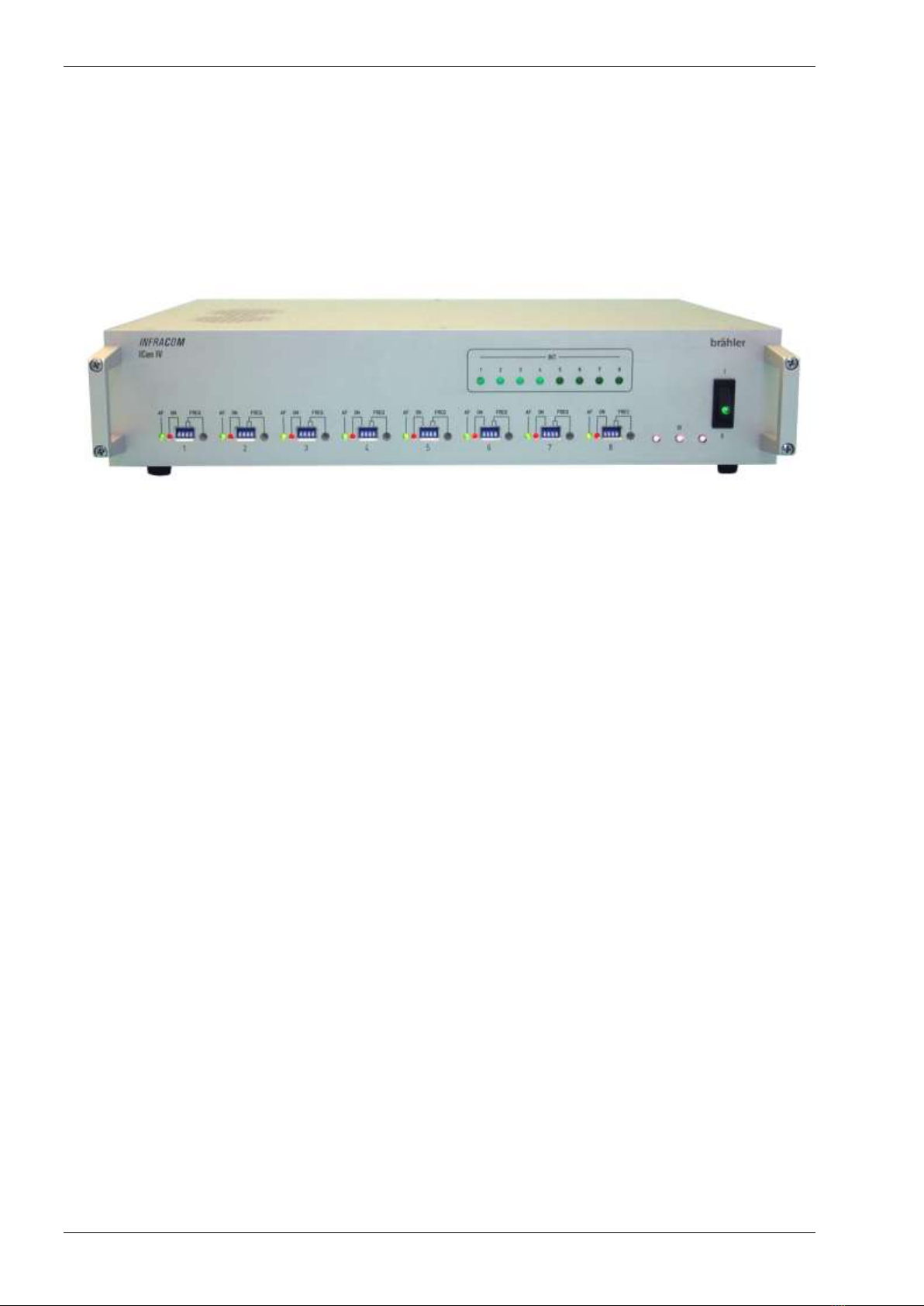
3.3 Compact transmitter ICen IV
Front View
The INFRACOM® Compact Transmitter ICen IV is part of the INFRACOM® system, which serves
the wireless language distribution by means of infrared light.
The sound signal is thereby converted into a frequency-modulated infrared signal and emitted via
transmitting diodes. With special INFRACOM® receivers the signal is re-converted into a sound
signal, which can be heard on a set of headphones. Up to 8 channels can be transmitted
simultaneously with an FM narrow band modulation.
The INFRACOM® Compact Transmitter ICen IV is provided for modulating the sound signals on
the different carrier frequencies in band IV. It also provides for signal amplification.
The Compact Transmitter consists of a 19" housing (2HU). Mounting brackets for rack assembly
are also available.
Seven languages and the original (floor channel) can be transmitted.
On the front right-hand side of the Compact Transmitter ICen IV there is a green POWER ON
showing the ON/OFF status. Next to this there are three infrared test diodes emitting the IR-signal.
With the IR receiver you can listen to the outgoing channels even without IR-Radiator. Operation
range is up to 3 meters.
The operating elements of the eight infrared channels are also on the front side of the console.
With miniature-switches on the front panel the frequency band can be chosen and the channels
can be switched ON or OFF. With a rotating switch it is possible to assign up to 32 transmission
channels. Each channel can be set from OR - Ch31.
Eight green LED (“INT”) indicate the status of the corresponding interpreter channel: green LED
means interpreter is “live”. This gives a quick overview about the occupied channels.

INFRACOM® ICen IV
Copyright by Brähler ICS 11
Rear view
The Compact Transmitter ICen IV contains the following sockets on the rear side:
OR-IN: XLR socket for feeding in the original channel (CDS sound / DIGIMIC sound). The
input is balanced via AF transformer.
OR-OUT: XLR socket for the output of the original sound. The output is also balanced via
AF transformer.
Trimming condenser for setting the volume of the original sound.
LINE-OUT: eight sockets for transmitting interpreter channels.
RF-LINK: BNC socket for cascading with other Compact Transmitter. Use BNC-T adaptor
for more than two units.
IR-LINE: BNC sockets 1 and 2 for connecting INFRACOM®radiators HLN82B. Up to 10
radiators can be connected directly at each output.
INTERPRETER: Two connecting sockets A36 for the connection of the interpreter
consoles.
Mains power connector
Separate ground connector.
ICen IV
INFRACOM®
12 Copyright by Brähler ICS
4. Installation and starting up
The Compact Transmitter has an ex-works mains voltage setting of 90 to 250 Volts by
50 to 60 Hz. If there is another voltage range you must not connect this equipment. In
connecting the system, special attention is to be paid to ensure that all cables are installed
in cable ducts or that they are fixed by cable clamps or adhesive tape in such a way that there is
no danger of somebody tripping over them.
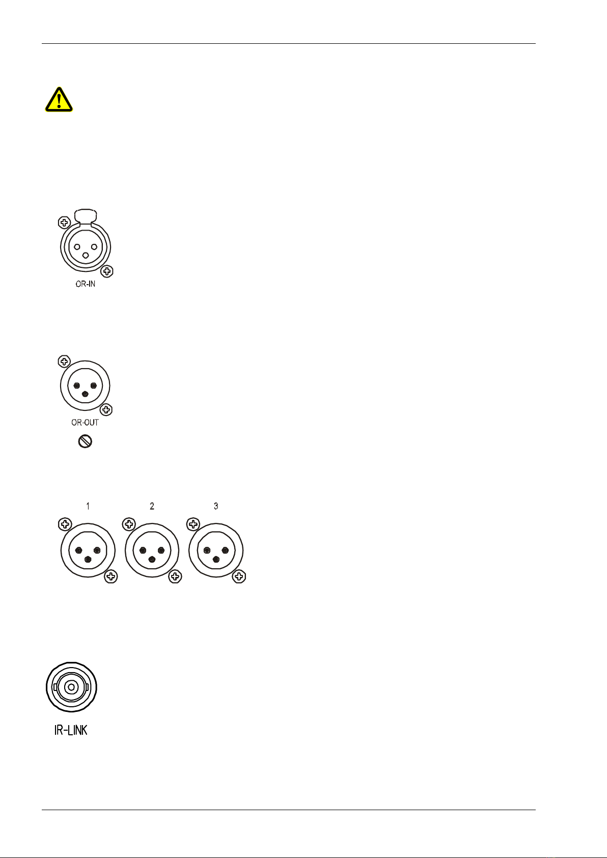
4.1 Connecting the OR-IN socket
XLR OR-IN connector (female): socket for feeding in the original channel
(CDS200 sound / AUTOMIC sound). The level can be set via the trimming
condenser.
The input is balanced via AF transformer.
4.2 Connecting the OR-OUT socket
XLR OR-OUT connector (male): socket for the output of the original sound. The
output is also balanced via AF transformer. The output level can be set via a
trimming condenser –this is done in dependence with the input level.
4.3 Connecting LINE-OUT sockets
XLR LINE-OUT connector (male): All eight
interpreter channels available for PA
system or for recording purpose.
4.4 Connecting RF-LINK socket
BNC socket for cascading another Compact Transmitter ICen IV: To manage more
In- and Outputs you can extend the INFRACOM system up to 16 line and more
outputs.
…

INFRACOM® ICen IV
Copyright by Brähler ICS 13
4.5 Connecting radiator sockets
BNC 1 and BNC 2: BNC sockets for connecting INFRACOM® radiators
IRad. Up to 10 radiators can be connected directly to each socket.
Caution: When wiring the radiators in band IV you must be aware of the following: Due to
the higher carrier frequencies the BNC cables to the radiators must have the same
length. Using two radiators in a row, the highest distance should not be greater than a
meter. Otherwise, there will be overlaps or extermination. Please note the application
examples in the corresponding chapter.
If there are more radiators needed we recommend the use of an active distributor SV/BNC. Our
planning department will be glad to help you.
4.6 Connecting A36 sockets
Two sockets A36 are provided for the connection to the interpreter consoles (i.e. DOL7/2). About
seven units may be connected directly to the transmitter. The total number depends on cable
length. If you have any questions don’t hesitate to ask. Our planning department will be glad to
help you.
4.7 Connecting mains power
Connect the delivered cable with this socket to ensure
the proper working of the Compact Transmitter.
ICen IV
INFRACOM®
14 Copyright by Brähler ICS
5. Starting Up
The power supply is turned on via the power switch on the front side of the Compact
Transmitter ICen IV.
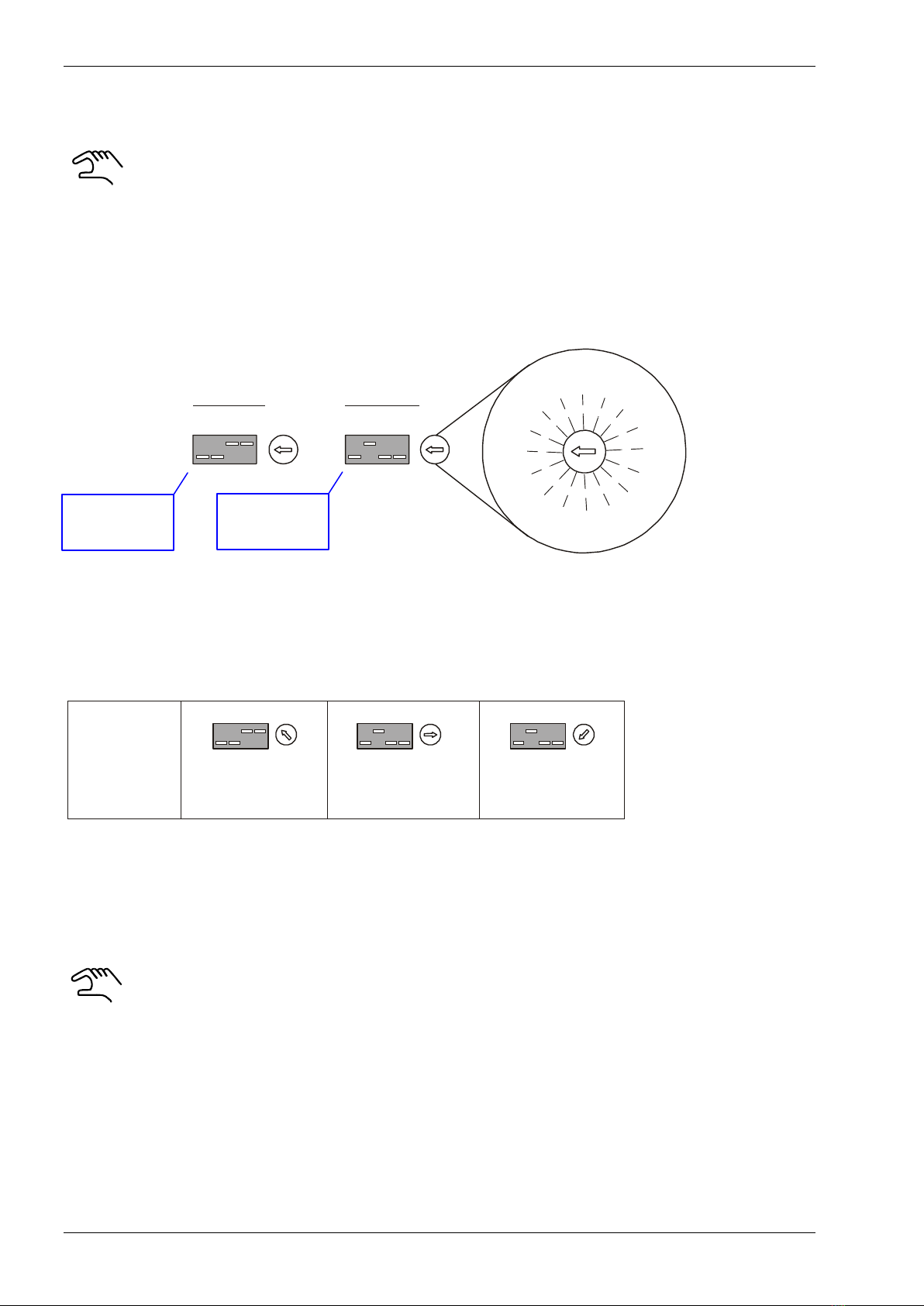
When you use the Compact Transmitter the first time it is necessary to adjust the
provided channels. This procedure will allocate the transmitter frequencies to the
respective channels.
For adjusting this allocation refer to the following figure. The scheme is enclosed with the Compact
Transmitter as a separate sticker which may be adhering to the front panel.
OFF
ON
Ch16 - Ch31
OFF
ON
ChOR-Ch15
1
9
2
0
2
1
2
2
2
3
2
4
2
5
2
6
2
7
2
8
2
9
3
0
3
1
1
6
1
7
1
8
OR
1
2
3
4
5
6
7
8
9
10
11
12
13
14
15
The setting for the floor channel to channel 15 is shown on the left figure above. The allocated
channel setting is done with the rotary switch.
The setting for channel 16 to channel 31 is shown on the right figure above
The left DIP-switch will activate the corresponding channel. DIP switch to ON means channel is
active.
5.1 Tuning input/output levels
Before starting a conference situation you should check the sound level in- and
output to avoid level change between floor sound and interpreter sound. This is done
by feed in a test signal to socket “OR-IN” and listening to the corresponding sound
level. Two high differences between the sound levels should be avoided.
Depending on the input level the output level can be adjusted using a trimmer below the "OR-OUT”
connector.
Other controls are not necessary for a successful event.
Examples:
Channel 2
Channel 24
Channel 30
Setting for
channel 16 to
channel 31
Setting for floor
channel to
channel 15

INFRACOM® ICen IV
Copyright by Brähler ICS 15
6. OPERATION
Once the INFRACOM system has been properly started up and checked, there is usually no need
for any further intervention from the operator.
Any switching involving the interpreter’s microphones and/or the language channels is done
directly at the interpreter console DOL7.
Most of the work involved with audio distribution should have been completed during the
preselecting of channels and system start-up.
Some features in conjunction with the interpreter console are:
Outgoing channel: During the actual event the toggle key can be used to move from one
(preselected) console channel A, B or C to the other.
Incoming channel (monitoring): For audio input the toggle switch is used to swap from the
floor channel to the (preselected) relay channel and back again.
The interpreter’s microphone is operating with the microphone button. A lamp integrated in
the switch indicates when "its" microphone is active.
If ever a microphone needs to be deactivated only briefly, this is done by pressing the
interrupt key. For as long as this key is pressed and held no audio signal is fed onto the
interpretation channel. If a microphone is turned off with the microphone key, then the floor
channel is automatically switched on to the corresponding interpretation channel.
6.1 LED AF and ON on front side
AF: This LED indicates a signal on this output (for example line 1).
ON: This LED represents the ON-status of the corresponding output
channel.
Remark: You should switch off not used channels to increase the IR
power.
ON- and OFF-status is set with the left DIP-switch.
6.2 Infrared test diodes
Three transmitting test diodes allow testing the receivers at a
maximum distance of 3 meters between the test-LEDs and the
receiver.
6.3 Interpreter LED
8 LEDs indicating the status of the corresponding
interpreter channel. Green LED means interpreter
in „live“.

ICen IV
INFRACOM®
16 Copyright by Brähler ICS
6.4 Overview
Illustration 1
Illustration 2
Power switch
3 IR diodes
Channel
selection
DIP-switch setting
channel range
ON LED
red
AF indicator
LED green
XLR
female
OR-IN
XLR male
OR-OUT
LINE OUT,
channel 1-8
Mains Power
Trimmer IN–
OUT adjust
Link connector
BNC
Radiator
connectors
A36 connector for
interpreter consoles
8 LEDs for
interpreter control

INFRACOM® ICen IV
Copyright by Brähler ICS 17
6.5 Technical Data ICen IV
The unit is complying with the international standard IEC914 and .
Connections
OR-IN (1 x XLR-socket)
for input of the original language (OR)
OR-OUT (1 x XLR-plug)
for balanced output of the original language, adjustable (–14 ... +6) dBV/600Ohm
LINE-OUT (8 x XLR-plug)
AF outputs for audio recording
IR-LINK (2 x BNC-socket)
1: Connection for up to 10 INFRACOM Radiators IRad
2: Connection of up to 10 further INFRACOM Radiators IRad
RF-LINK (1 x BNC-socket)
for cascading (RF) with further ICen IV
INTERPRETER (2 x A36-socket) for connection of Interpreter Consoles DOL7
Features
Green lighted mains switch for power ON indication
Red LEDs for channel ON indication
Green LEDs for audio available (AF)
8 LEDs for interpreter control
Transmission frequency
1935 kHz –3175 kHz (channel 31) in 40kHz steps
Intermediate frequency
455 kHz
Measurements
Distortion: < 0.2%
Signal-to-noise ratio: > 70dB
Channel separation: > 60dB
Power Supply
Mains power: (90 ... 250)VAC, (50 ... 60)Hz
Power consumption: 40VA max
Housing
19”, 2 HE, Aluminium, “silver” anodized
W x H x D: (433 x 88 x 305)mm
Weight
4.6kg

ICen IV
INFRACOM®
18 Copyright by Brähler ICS
6.6 Optional accessories
(not included in delivery)
INFRACOM Radiator IRad
INFRACOM Receiver IRX32
INFRACOM Interpreter Unit DOL7/2
SV/BNC distribution amplifier to extend the number of radiators
DNT03 Power supply for DOL7 interpreter consoles
BNC cable (50 Ohm) different length available
INFRACOM® ICen IV
Copyright by Brähler ICS 19
7. Applications
In the following you see some examples in form of a block diagram:
IRX32
IRad
8x line out
(recording, PA)
OR in
ICen IV
link
A36
BNC
OR out
Ka8
Ka1
DOL7/2E
Floor-
Signal
A36
cabling
RG58 Length A
Length A
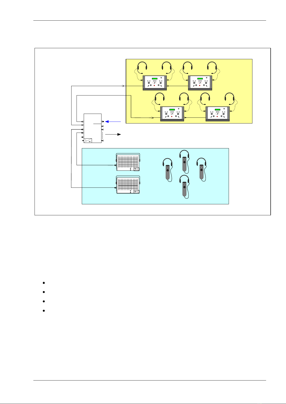
Application 1
This diagram shows a complete application for a seven channel (OR + 6) interpreter system.
Monitoring part is the Receiver IRX together with the IR-Radiator IRad. The length of cable to the
radiators must be equal for both radiators (Length A).
INFRACOM System Components
ICen IV: Compact Transmitter
DOL7/2: Interpreter console for 2 interpreters (7 channels) with A36 cabeling
IRad: Radiator with cabling BNC (RG58)
IRX32: Receiver for up to 32 channels
ICen IV
INFRACOM®
20 Copyright by Brähler ICS
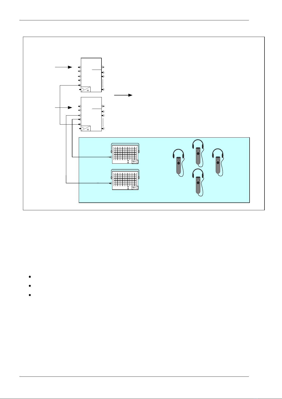
The next diagram (Application 2) shows the extension to a 16 channel system:
IRX32
IRad
IR
transmitter
16x line out
(recording, PA)
OR in
ICen IV
link
A36
BNC
OR out
Ka8
Ka1
OR in
ICen IV
link
A36
BNC
OR out
Ka8
Ka1
8x analog in
8x analog in
Length A
Length A
Application 2
Two of the Compact Transmitters ICen IV are linked to one system. The monitoring part consists of
the Receiver IRX together with the IR-Radiator IRad. Notice: The length of cable to the radiators
must be equal for both radiators (Length A).
INFRACOM System Components
ICen IV: Compact Transmitter with floor signal, 16 interpreter channels and 16 line outputs.
IRad: High Power Radiator
IRX32: Receiver for up to 32 channels
Table of contents


