D-Box Milano User manual
192-914-0010-EN6 – November 2020 Technical Support: 1-888-442-3269 ext. 251
Fax: 450-442-3230
E-mail: supportmfx@d-box.com
Visit us at: www.d-box.com
INORCA
INTEGRATED RECLINERS
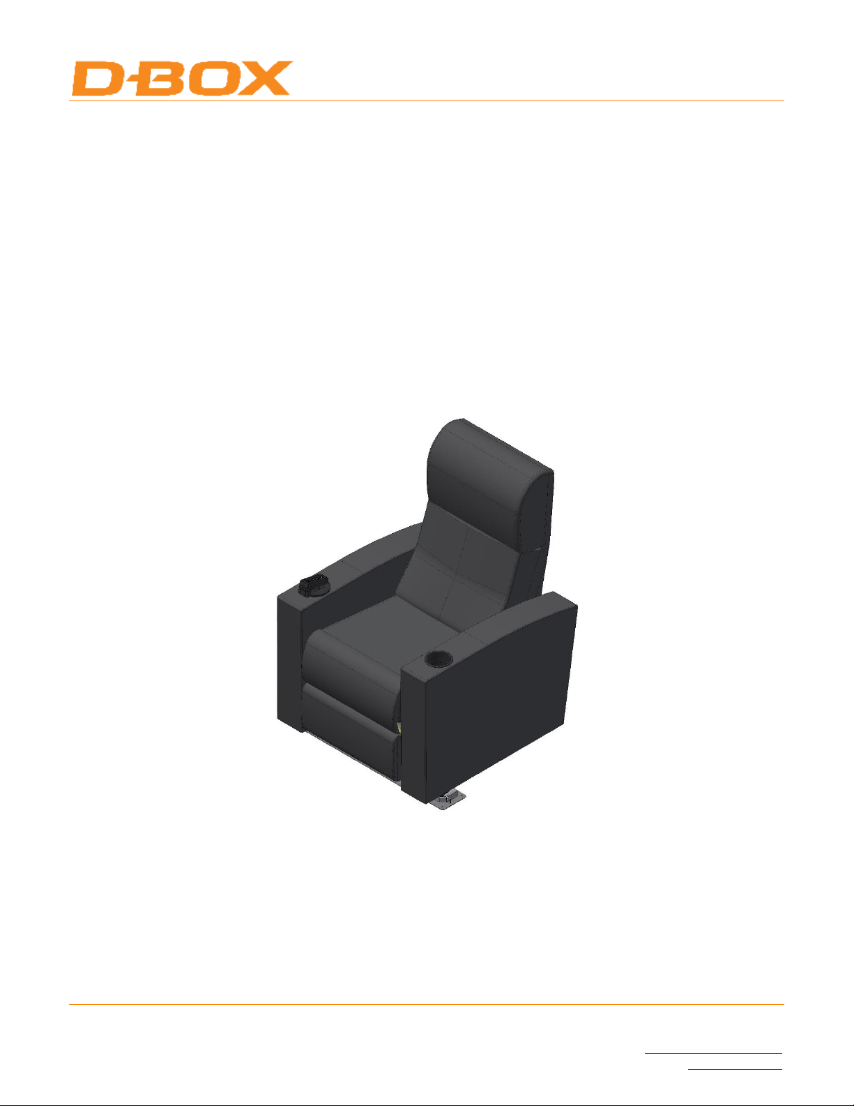
Models Milano, Lucca, Malibu and Euphoria –Welded Triangle Base - 2 Front Axes
120V –230V Versions
MOTION KIT and RECLINER INSTALLATION
GUIDE

LIMITATION OF LIABILITY
IN NO CASE AND IN NO WAY, THE PROVIDER OF THIS PRODUCT (D-BOX TECHNOLOGIES INC.,
THE DISTRIBUTOR OR RESELLER, OR ANY OTHER PARTY ACTING AS PROVIDER) SHALL BE
LIABLE AND SUED TO COURT FOR DAMAGE, EITHER DIRECT OR INDIRECT, CAUSED BY AND
TO THE USER OF THE MOTION SYSTEM AND WHICH WOULD RESULT FROM AN IMPROPER
INSTALLATION OR MISUSE OF THE PRODUCT. “MISUSE” AND “IMPROPER INSTALLATION”
MEAN, WITHOUT LIMITATION, INSTALLATION AND USE NOT CORRESPONDING TO THE
INSTRUCTIONS IN THIS MANUAL.
COPYRIGHT 2020©D-BOX TECHNOLOGIES INC. ALL RIGHTS RESERVED. D-BOX IS A
REGISTERED TRADEMARK OF, D-BOX TECHNOLOGIES INC. AND/OR ITS AFFILIATES IN
CANADA AND CERTAIN OTHER COUNTRIES. ALL OTHER TRADEMARKS MENTIONED IN THIS
DOCUMENT OR WEBSITE ARE THE PROPERTY OF THEIR RESPECTIVE OWNERS.

I
TABLE OF CONTENTS
INTRODUCTION ....................................................................................................................................................................................................................1
SAFETY MATERIAL AND INSTRUCTIONS .................................................................................................................................................................2
SIGNAL WORDS................................................................................................................................................................................................................2
SAFETY SIGNS AND LABELS ......................................................................................................................................................................................2
SAFETY INSTRUCTIONS...............................................................................................................................................................................................3
TOOLS LIST .............................................................................................................................................................................................................................4
CONSUMABLES LIST ...........................................................................................................................................................................................................4
MOTION SYSTEM INSTALLLATION PROCEDURE .................................................................................................................................................5
PREPARATION .................................................................................................................................................................................................................5
TERMINATING THE ACM .......................................................................................................................................................................................7
INSTALLING THE POWER CABLE ......................................................................................................................................................................8
INSTALLING THE LEFT AND RIGHT ACTUATORS......................................................................................................................................8
INSTALLING THE ACTUATOR PROTECTOR ...............................................................................................................................................10
ROUTING AND SECURING ACTUATOR CABLES........................................................................................................................................11
INSTALLING THE REAR PIVOT ........................................................................................................................................................................11
INSTALLING THE ACM .........................................................................................................................................................................................12
CONNECTING THE ACTUATOR CABLE TO THE ACM.............................................................................................................................12
INSTALLING THE POWER CABLE ...................................................................................................................................................................14
INSTALLING THE MOTION INTENSITY CONTROLLER .........................................................................................................................14
CABLE ROUTING .....................................................................................................................................................................................................15
MOTION SYSTEM THEATRE INSTALLATION PROCEDURE ...........................................................................................................................16
EQUIPMENT DESCRIPTION.....................................................................................................................................................................................16
MARKING THE CONCRETE ANCHORS LOCATIONS......................................................................................................................................17
DRAWING THE REFERENCE LINES................................................................................................................................................................17
MARKING THE DRILLING LOCATIONS .........................................................................................................................................................17
DRILLING AND CLEANING THE CONCRETE SCREW ANCHOR HOLES................................................................................................19
SAFETY INSTRUCTIONS ......................................................................................................................................................................................19
DRILLING THE CONCRETE ANCHOR HOLES .............................................................................................................................................19
LAYING THE CABLES..................................................................................................................................................................................................20
LAYING THE RECLINER TO RECLINER DATA CABLES..........................................................................................................................20
LAYING THE PROJECTION ROOM TO AUDITORIUM DATA CABLES ...............................................................................................21
TERMINATING THE CABLES .............................................................................................................................................................................22
TESTING THE CABLES..........................................................................................................................................................................................23

II
INSTALLING THE WELDED TRIANGLE BASE .................................................................................................................................................24
PREPARATION .........................................................................................................................................................................................................24
PROCEDURE..............................................................................................................................................................................................................24
CONNECTING THE CONTROLLERS......................................................................................................................................................................25
RECLINER CONNECTIONS –OVERVIEW .....................................................................................................................................................25
CONNECTING THE RECLINER CONTROLLER............................................................................................................................................26
CONNECTING THE MOTION INTENSITY CONTROLLER.......................................................................................................................26
INSTALLING THE RECLINER ..................................................................................................................................................................................27
Preparation ..........................................................................................................................................................................................................27
Procedure .............................................................................................................................................................................................................27
MAKING CONNECTIONS ...........................................................................................................................................................................................29
DAISY-CHAINING THE RECLINERS ................................................................................................................................................................29
TESTING THE DAISYCHAINED RECLINERS................................................................................................................................................30
MAKING THE FINAL CONNECTIONS...................................................................................................................................................................31
FUNCTIONNAL TESTING.....................................................................................................................................................................................31
CONNECTIONS DIAGRAM...................................................................................................................................................................................32
TESTING CONTINUITY .........................................................................................................................................................................................32
COMPLETING THE INSTALLATION .....................................................................................................................................................................33
CLEANING UP ................................................................................................................................................................................................................33
MAINTENANCE TASKS ...................................................................................................................................................................................................34
ACM REPLACEMENT ..................................................................................................................................................................................................34
ACTUATOR REPLACEMENT....................................................................................................................................................................................37
REMOTE CONTROLLER REPLACEMENT...........................................................................................................................................................40
REMOTE CONTROLLER HOUSING REPLACEMENT .....................................................................................................................................41
INSTALLATION PROCEDURE IF THE TAB IS BROKEN..........................................................................................................................42
ANNEX A –SAFETY CLEARANCE RECOMMENDATIONS.................................................................................................................................43
ANNEX B –CONNECTIONS............................................................................................................................................................................................46
ANNEX C RECLINER CLEARANCE PROCEDURE.......................................................................................................................................................
Introduction
1
INTRODUCTION
CAVEAT: READ THIS GUIDE CAREFULLY BEFORE PROCEEDING WITH THE INSTALLATION.
The purpose of this guide is to provide detailed instructions about installing the D-BOX welded triangle base with a
recliner recliner –Inorca Milano, Lucca, and Euphoria- in a movie auditorium.
Concerning recliner orientation, left and right are viewed from a seated position.
The following sign indicates an installation tip:
Read this guide before installing the equipment and keep it in a safe place.
Check the content of pallets and boxes to make sure you have all the equipment required to proceed with the
installation. Contact D-BOX if any equipment is missing.
This manual suits for next models
2
Table of contents
Other D-Box Indoor Furnishing manuals

Popular Indoor Furnishing manuals by other brands

Regency
Regency LWMS3015 Assembly instructions

Furniture of America
Furniture of America CM7751C Assembly instructions

Safavieh Furniture
Safavieh Furniture Estella CNS5731 manual

PLACES OF STYLE
PLACES OF STYLE Ovalfuss Assembly instruction

Trasman
Trasman 1138 Bo1 Assembly manual

Costway
Costway JV10856 manual


