D-CUT Silverise Series User manual
SERIES
O
peration Manual
D-Cut TD-080 Wet Tile Saw
FOR YOUR SAFETY
This saw can be operated safely only when the operating instructions
have been completely read and strictly adhered to. It is
recommended to receive practical instruction before using the saw
for the first time.
Always inspect cable and plug before using the saw. The outlet
must be grounded. Have damage repaired only by a qualified
professional.
Do not use the saw in standing water or expose rain.
Wear hearing protection and safety goggles.
zAlways remove the plug from the power supply socket before removing saw
from work area, when interrupting work and when not using the saw.
zInsert the plug into the power socket only when the saw is switched off.
zAlways place the cable away from the saw towards the outside of the saw
table.
zDo not carry the saw by the cable.
zWear sturdy footwear.
zDo not use the saw when the blade is not installed properly.
zAlways switch off the saw before lifting the table for cleaning.
zOnly use original D-Cut accessories.
zNever leave the saw running unattended.
zKeep guards in place. Adhere to safety guidelines: (ANSI) American Safety
Standards Institute.
zNever stand or lean on equipment. Serious injury could occur if the machine
is tipped or is unintentionally contacted.
zDo not over reach. Keep footing and balance at all times.
zDisconnect tools. Before servicing, and when changing accessories such as
blades or profile tools. Turn off equipment!
zUse the correct tools. Do not force the equipment or accessory to do a job
for which it was not designed
zUse proper extension cord. Improper cord length and/or gauge is the
leading cause of premature electric motor failure! When in doubt use
heavier gauge cord.
zAn extra space needs to be remained around the machine as the working
table moves over the machine edge.
2

INNOVATION PUT TO WORK
Here at D Cut Products, Inc. We are always looking
to come out with new innovative products.
Check out Our Website for Updates at
www.dcutproducts.com
or contact us at
The serial number of your saw is
located on the left side above
the switch.
FOR YOUR (90 DAY) WARRANTY TO BE EFFECTIVE ON ALL
ELECTRICAL MOTOR AND PARTS SUCH AS THE SWITCH AND THE
CONTROL DEVICE, GAS ENGINE, AND PARTS, ALSO FOR YOUR
(1) ONE YEAR WARRANTY ON ALL OTHER PARTS, EXCLUDING
ABOVE COMPLETE THE WARRANTY CARD (PLEASE INCLUDE THE
SERIAL NUMBER) AND MAIL IT IN AS SOON AS POSSIBLE.
3

4
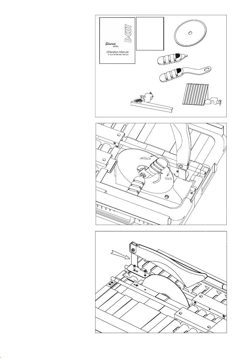
Fig.1
Warranty
card
Contents in the Box:
(1) Continuous rim
diamondblade,
(2) 45 degree
attachments, (1) wrench
set, (1) operation manual
and Warranty card.
Installation of the Blade
Open the “Open/Close
cover” and use provided
the wrench to install the
provided blade. Make
sure the cutting direction
shown on the blade is the
same direction of the
running motor.
Warning: The rotating
direction of the blade is
very important for cutting
correctly. Fig.2
Fig.3
Installation of the Guard
Use provided wrench to
install the blade guard
and the supporting bar
shown in Fig.3.
Warning: Do not remove
the middle screw as this is
to hold the motor housing.
5
6
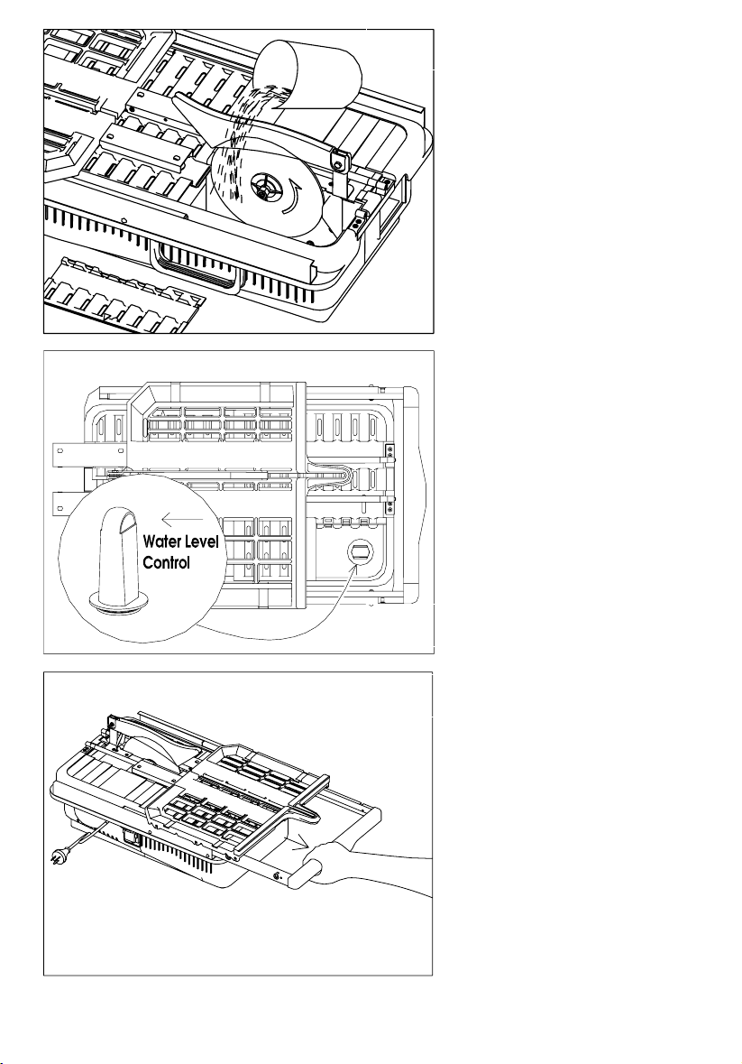
Fill Water
Open the “Open/
cover” then pour water into
the tray. Water can be
added or refilled as
needed during saw
operation.
Close
Supporting Bar
Extend out fully the
supporting bar before
moving the table. As
shown in Fig.6
Fig.4
Water Level Limit
The plug for the water tray
shown in Fig.5 is also a
water level control device.
Over filling the water will be
drained from the opening
at the top of the plug to
protect the motor.
Fig.5
Fig.6
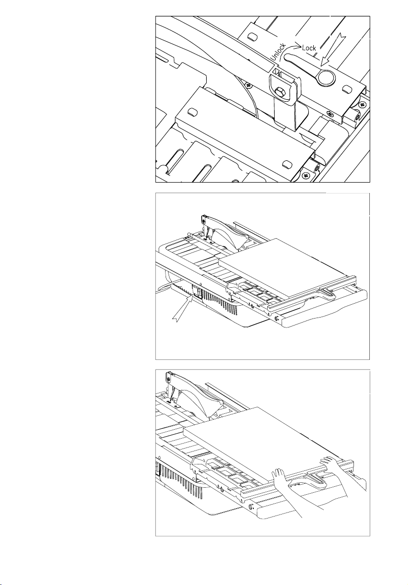
Placing a Tile on the Table
Place a tile on the moving
table, flush against the
table back shown in Fig.8.
And then turn on the
motor.
Table Lock/Unlock Lever
Unlock the table as shown
in Fig.7 before moving the
table.
Fig.7
Fig.8
Cutting
After placing the tile on
the moving table, use
two hands to hold both
table back and the tile,
slowing push towards to
the running blade as
shown in Fig.9
Warning:
Never put hand(s) on the
notch port of the moving
table.
Fig.9
7

Attachment
Use the attachment shown
in Fig.10 as a limitation
stopper when repeatedly
cutting same size of the tile.
Warning:
Remove this attachment
from the table when not
needed.
Fig.10
0-90 Degree Attachment
Unlock the screw o
attachment shown in Fig.11
and set it to the proper
angle between 0-90
degrees, then lock the
degree setting screw.
Warning:
Remove this attachment
from the table when not
needed.
n the
Fig.11
4
5 Degree Attachment (2)
Set this attachment in right
position where 45 Degree is
assured, then lock the
attachment to the table
back shown in Fig.12.
Warning:
Remove this attachment
from the table when not
needed.
Fig.12
8
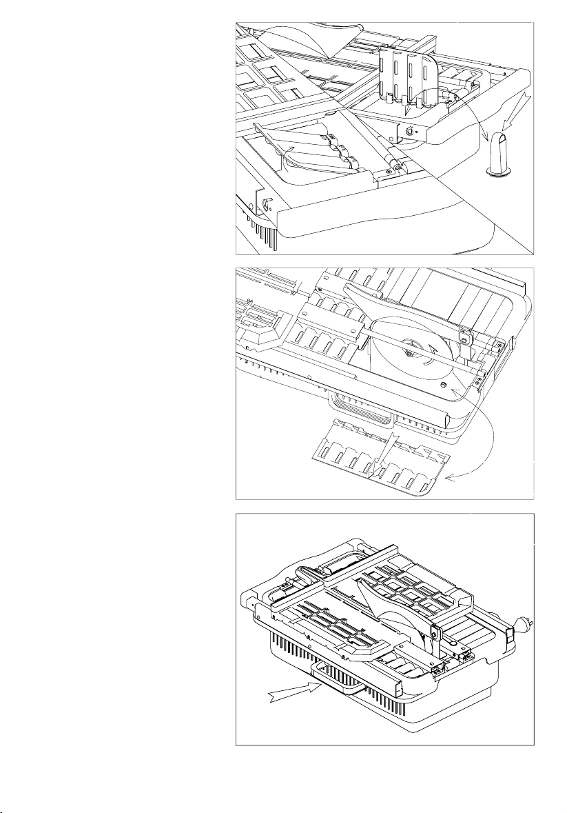
Drain the Water
Open the top cover right
above the water plug
shown in Fig.13 and pull the
plug.
Fig.13
Cleaning the Saw
Pour a bucket of clean
water from the “Open/
Close cover” throughout
the water tray and use the
provided scraper to clean
and remove the cutting
debris and slurry
Fig.14
Carrying
A conve
Handle
nient carrying
handle is located on the
side of the saw, opposite to
the switch, for
transportation purpose.
Fig.15
9

10

Specifications:
11
TD-080 Parts List
Parts Descri
p
tion Q't
y
Parts Descri
p
tion Q't
y
1 Table assembly 1 28 Small pulley 1
2 Screw M4 4 29 Large pulley 1
3 Hex nut M4 4 30 Shaft ring 12mm 2
4 Open Ring 4mm 6 31 Water Tank 1
5 Roller on supporting frame 6 32 Seal spacer 6mm 4
6 Pin for roller 6 33 Flat spacer 6mm 4
7 Support frame 2 34 Inner water stopper 1
8 Water tank cover 1 35 Hex nut M6 1
9 Wire connector 1 36 Inner flange 1
10 Electrical wire 1 37 Blade 1
11 Shaft for blade 1 38 Locking nut M10 1
12 Bearing cover 1 39 Outer flange 1
13 Screw M6 2 40 Hex screw M6 1
14 Switch assembly 1 41 Open/close cover 1
15 Screw M4 2 42 Hex nut M6 1
16 Hex nut M4 2 43 Blade guard bracket 1
17 Motor cover 1 44 Screw M4 3
18 ST-screw 4.2×13 6 45 Nut for guard bracket 1
19 Guide duct 1 46 Blade guard 1
20 Bearing 628 1 47 Guide positioning plate 2
21 Motor fan 1 48 Flat-head screw M4 5
22 Motor assembly 1 49 Guide base 4
23 Capacity 1 50 Support bar assembly 1
24 Hex nut M8 1 51 Guide assembly 2
25 Motor locking bar 1 52 0-45 degree attachment 1
26 Bearing 6002 1 53 45 degree attachment 1
27 Timing belt 1 54 Table Lock/Unlock Lever 1
Motor: 110V-120V/ 60Hz, 1.0H
p
/ 220V-240v, 50-60Hz, 735w
Rip Cut 25.5inch / 650mm
Diagonal Cut 18inch / 450mm
Cutting Depth 1-1/2inch / 40mm
Blade Size 8inch / 200mm
Blade Bore Size 5/8inch / 22.2mm, 25.4mm
Size(L×W×H) 610mm×420mm×225mm
Weight 31Lb/14KGS
12
Trouble shooting:
1No
ade to make sure s o ght
borking piece is 8)
2Mo
ann tio
br cords for da g
3. Tab ng cutting p e
a allation.
b earing status.
4 osi
arking table rn m nds
.
b. Change blade.
Pro ts contact you t zed
NVIRONMENT P TEC
.t cutting straight
.Check bla it’ n ti
.Make sure w flush against table back (Fig.
.tor doesn’t work
.Check power source co ec n.
.Check powe ma e.
le vibration duri roc ss
. Check blade inst
. Check blade-w
. L ng cutting speed
.Back-up the wo
and the re-start the motor
, tu the otor off for 30 seco
* blem still exis r au hori D Cut Service Center
E AL RO TION
Waste electrical products sh not be disp hold
. Please recycle where faciliti it. C
y or retailer for recycl ad .
D CUT P
1041N. Lo
ombard
l: 630-9 916-9101
www.dcutproducts.com
ould osed of with house
waste es ex heck with your local
Authorit ing vice
RODUCTS, INC.
mbard Road
L , IL 60148 USA
Te
Email: sales
16-9100 Fax: 630-
@dcutproducts.com
This manual suits for next models
1
Table of contents
Other D-CUT Saw manuals


