D-I INDUSTRIAL DMT 220DL User manual

MARINE TRANSMISSION
INSTRUCTION MANUAL
The users should read this manual thoroughly before operation and
observe the operating method and pre autions for more effe tive operation.
MODEL
DMT 220DL

Introduction
This manual contains descriptions of construction, operation principle, correct
operation, handling method, caution for installation, simple maintenance and
overhaul, etc. regarding D-I Marine transmission (DMT220DL).
APPLICATION HYDRAULIC MARINE TRANSMISSION
MODEL DMT220DL
To use this product safely and correctly the users must read this manual
thoroughly and understand it enough before operation.
Keep this manual at a designated place for next time.
Please read the contents marked with in this manual and use this product
correctly.
Users must follow the instruction now that the contents marked with are very
important information on safety.
In this manual, DANGER degrees for wrong handling are divided into 4 degrees as
following table.
If the contents with this mark are ignored and it is
mishandled, urgent situations such as death, serious
injury could occur.
If the contents with this mark are ignored and it is
mishandled, it is possible to suffer a loss of life and
property or serious injury.
If the contents with this mark are ignored and it is
mishandled, a loss of property could occur.
The contents with this mark should be read carefully.

C O N TE N TS
CHAPTER 1 - - - - - - - - - - OVERVIEW
CHAPTER 2 - - - - - - - - - - STRUCTURE
CHAPTER 3 - - - - - - - - - - PRINCIPLES OF OPERATION
CHAPTER 4 - - - - - - - - - - HYDRAULIC SYSTEM
CHAPTER 5 - - - - - - - - - - INSTALLATION
CHAPTER 6 - - - - - - - - - - OPERATION
CHAPTER 7 - - - - - - - - - - MAINTENANCE AND OVERHAUL
CHAPTER 8 - - - - - - - - - - TROUBLESHOOTING
CHAPTER 9 - - - - - - - - - - DISASSEMBLY AND ASSEMBLY
OPTION Live P.T.O.
HOW TO DISASSEMBLE THE OUTPUT COUPLING
ANNEX Ⅰ TABLE OF PERIODIC OVERHAUL
ANNEX Ⅱ PARTS ORDER SHEET
ANNEX Ⅲ WARRANTY LETTER

THE MANUAL OF MARINE TRANSMISSION
━━━━━━━━━━━━━━━━━━━━━━━━━━━━━━━━━━━━━━━━━━━━━
- 1 -
CHAPTER 1 – OVERVIEW
1-1. FUNCTION
The D-I marine transmission described in this manual is the power-transmitting
device which transmits the power generated from Engine to Propeller.
The main functions are the ahead, neutral, astern and reduction of speed at fixed
rate. The marine transmission has the structure which can safely endure the power
generated by propeller’s propulsion.
The power for the ahead and astern is transmitted by clutches with hydraulic
multiple plates. The necessary hydraulic system is integral inside.
1-2. SPECIFICATIONS
※ The weight does not include the fly wheel housing Ass’y, coupling Ass’y,
propeller coupling and mounting brackets.
Model Reduction
ratio
Max.
Input
speed
Max.
Input
torque
Operating
pressure
Lubricating
pressure
Dry
Weight
Flow of
cooling water
(rpm) (kgf-m) (kg/㎠) (kg/㎠) (kg) (ℓ/min)
DMT220DL
3.50
4.04
2500
209
20~26 2~4 440 90~120
4.47 198
4.72 177

THE MANUAL OF MARINE TRANSMISSION
━━━━━━━━━━━━━━━━━━━━━━━━━━━━━━━━━━━━━━━━━━━━━
- 2 -
D-I marine transmission must be applied to marine engine with regulated
capacity, otherwise the slip, overheat or breakage could happen to power transmission
system.
The capacity for use must be observed and if there are any inquiries, please
contact D-I Industrial Co., Ltd.
D-I marine transmission must not be used for the marine engine which is
rotated clock wise seen from the rear of the engine.
If D-I marine transmission needs to be used for the engine with clock wise rotation,
please contact D-I Industrial Co., Ltd. for consultation.
[ C.C.W ENGINE ] [ C.W ENGINE ]

THE MANUAL OF MARINE TRANSMISSION
━━━━━━━━━━━━━━━━━━━━━━━━━━━━━━━━━━━━━━━━━━━━━
- 3 -
CHAPTER 2 - STRUCTURE
2-1. OVERVIEW
D-I marine transmission is the reduction device which generates ship’s propulsion
and consists of five(5) major components such as input shaft sub Ass’y, astern
shaft sub Ass’y and output shaft Ass’y, etc. in driveline system.
Now that the hydraulic clutches controlled by oil pressure are applied for ahead
and astern operation, there are pump Ass’y to generate oil pressure, oil cooler,
selector valve Ass’y, valve holder Ass’y and pump holder Ass’y in hydraulic system.
The marine transmission is directly mounted to engine flywheel housing by bolts.
The power is transmitted from the outer part which is assembled onto engine
flywheel to input shaft through the inner part with rubber blocks.
In other words, the power is transmitted by the flexible coupling between engine
and marine transmission.
Responsibility for Torsional vibration
Torsional vibration analysis is carried out by the engine maker or independent consultants.
D-I Industrial Co., Ltd. can provide relevant data for the analysis of marine transmission
supplied by D-I Industrial Co.,Ltd.
The equipment installer is responsible for ensuring the torsional compatibility of the
propulsion system.
D-I Industrial Co.,Ltd. has no liability for noises/damages of marine transmission and
damages of flexible coupling and other drive units caused by that kind of vibration.
For safe operation, users should refer to instruction manual prior to operation.
[Fig-1] Construction of Marine transmission
ASTERN SHAFT ASS’Y
Flexible Coupling
(CENTA coupling)
INPUT SHAFT ASS’Y
OUTPUT SHAFT GROUP

THE MANUAL OF MARINE TRANSMISSION
━━━━━━━━━━━━━━━━━━━━━━━━━━━━━━━━━━━━━━━━━━━━━
- 4 -
2-2. INPUT SHAFT SUB ASS’Y
1) Outer Part
The outer part has the grooves in regular shape for the rubber blocks to be
assembled to transmit the power. It is assembled to engine flywheel by
screws.
2) Inner Part
The Inner part is assembled to input coupling by reamer bolts and has the
structure for the rubber blocks to be assembled.
3) Rubber blocks
They are rubber products and relieve the rotational vibration by engine which
means they let the power transmitted smoothly.
4) Input shaft
The input shaft is assembled to the input coupling by spline and shrink-fitted
to input clutch housing. Key on the input shaft is assembled to pinion
coupling to transmit the power of LIVE PTO.
5) INPUT SHAFT ASS’Y
The input shaft sub Ass’y consists of input clutch housing, clutch piston, steel
plates, sintered plates, back plate and return spring.
The steel plates have inner teeth which engage with the input pinion and
sintered plates have outer teeth which engage with the input clutch housing.
The steel plates and sintered plates are alternately assembled one by one and
when the selector valve lever is shifted in ahead position, the oil pushes the
clutch piston to actuate the input clutch. At this moment, the steel plates and
sintered plates are engaged and the power is transmitted from the input clutch
housing to input pinion.
When the lever is shifted in neutral position, the clutch piston returns to its
original position by the return spring. At this moment, the oil is drained from
the clutch piston section and the clutch is automatically disengaged.
1
3
2
5
4
THE MANUAL OF MARINE TRANSMISSION
━━━━━━━━━━━━━━━━━━━━━━━━━━━━━━━━━━━━━━━━━━━━━
- 5 -
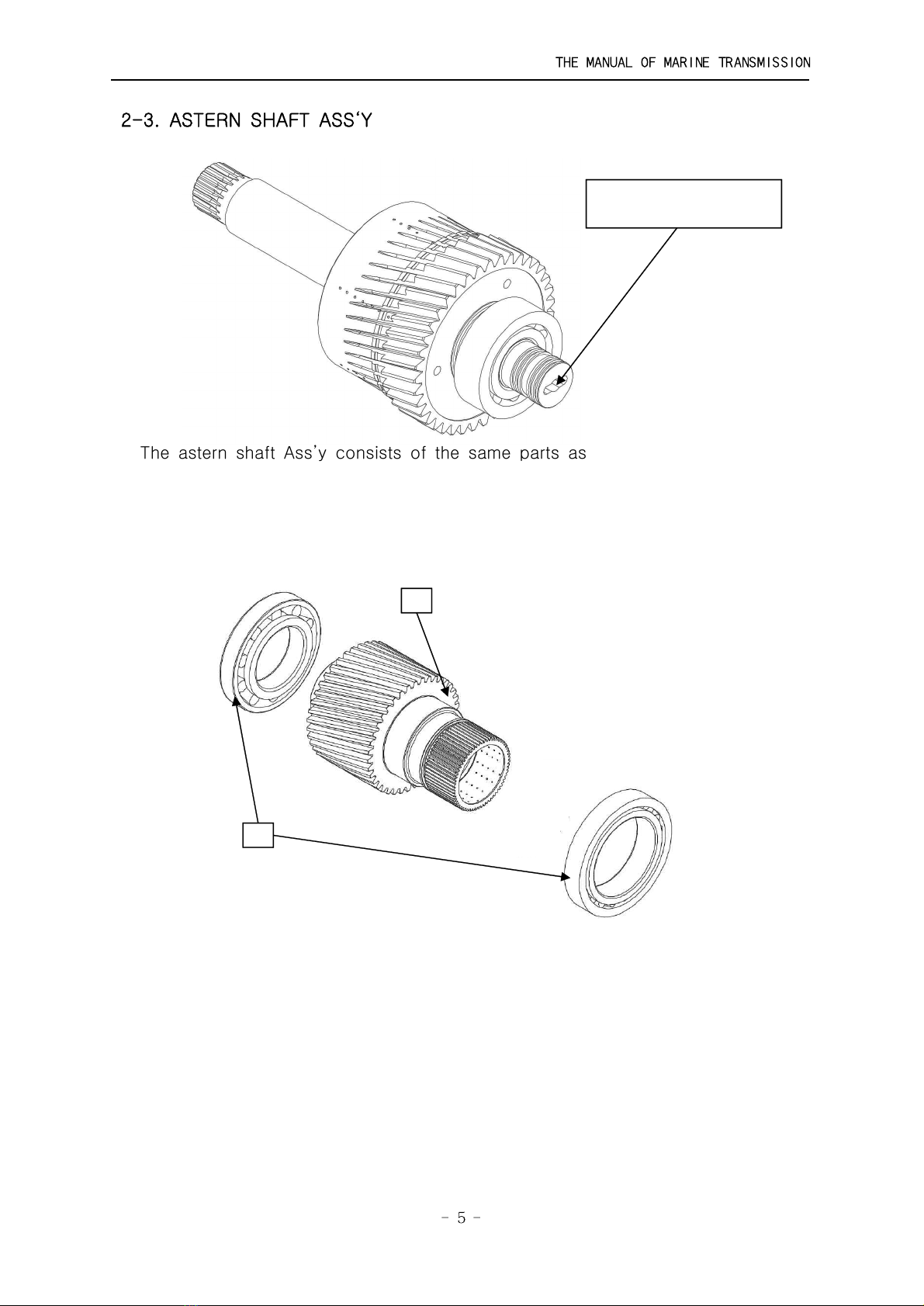
2-3. ASTERN SHAFT ASS‘Y
The astern shaft Ass’y consists of the same parts as the input shaft Ass’y
except for the astern shaft sub Ass’y and pump driving block at the rear of
shaft.
2-4. PINION
1) Taper roller bearing
Taper roller bearings which are shrink-fitted to pinions are assembled to sides
of case and case cover. They support the load generated by pinions’ rotation.
2) Pinion
The input and astern pinion are identical and are engaged with the output
shaft gear. When the ahead or astern operation is on, the power is transmitted
from the input shaft sub Ass’y to output shaft gear.
Unlike other models, the shim adjustment for DL model is carried out after
assembled to case Ass’y.
1
2
A
A
Key slot for driving gear
of hyd’ pump

THE MANUAL OF MARINE TRANSMISSION
━━━━━━━━━━━━━━━━━━━━━━━━━━━━━━━━━━━━━━━━━━━━━
- 6 -
2-5. OUTPUT SHAFT ASS‘Y
1) Output shaft
Output Shaft has the support by 2 taper roller bearings and shrink-fitted with
output gear. ON the input side’s taper, the output coupling is assembled.
2) Output gear
The output gear is shrink-fitted to output shaft and engaged with the input and
astern pinion at all times.
3) Taper roller bearings
The taper roller bearings fixed on both sides of the output shaft support the
thrust force generated from the propeller during the ahead or astern actuation.
4) Output coupling
The output coupling is assembled to output shaft in taper and is firmly fixed
by a plate and screws.
2-6. CASE, CASE COVER, BEARING CARRIER
The case, case cover and bearing carrier is made of cast iron.
3
1
2
4
THE MANUAL OF MARINE TRANSMISSION
━━━━━━━━━━━━━━━━━━━━━━━━━━━━━━━━━━━━━━━━━━━━━
- 7 -
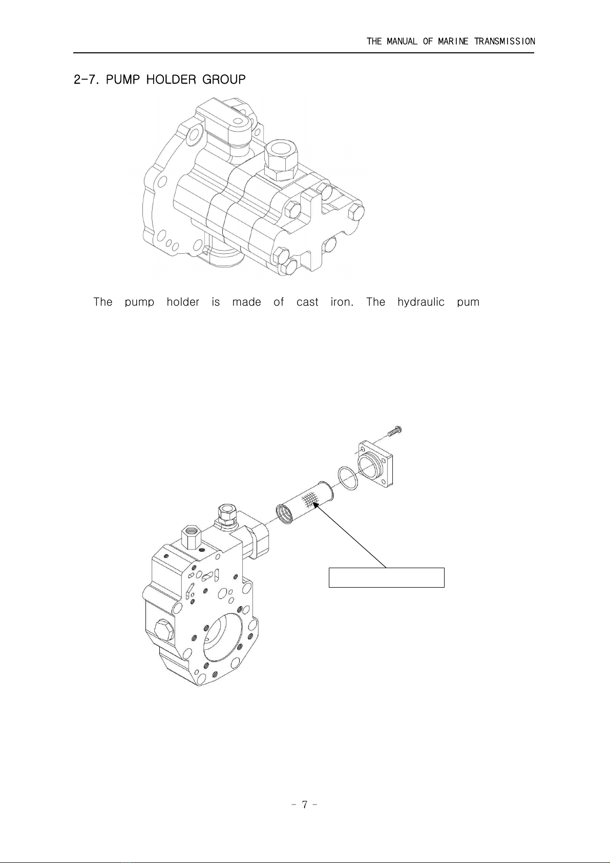
2-7. PUMP HOLDER GROUP
The pump holder is made of cast iron. The hydraulic pump is the
circumscribed gear type, and bolted on the pump holder. The pump driving
gear is driving block and spline fitted at the end of the astern shaft, and
rotated at the same speed as that of engine, but in the opposite to engine
direction.
2-8. SECONDARY OIL FILTER
This is attached to the inlet of the valve holer to re-filtrate oil which is
filtered through a strainer on the inlet side of the pump before leading it to
the bearing carrier.
it has the structure to easily be cleansed by disassembling only filter’s cover.
Periodic Inspection : Refer to ANNEX Ⅰ
OIL FILTER ASS’Y

THE MANUAL OF MARINE TRANSMISSION
━━━━━━━━━━━━━━━━━━━━━━━━━━━━━━━━━━━━━━━━━━━━━
- 8 -
2-9. SELECTOR VALVE ASS’Y
1) Selector valve body
The selector valve body is made of cast iron, and bolted on the valve holder.
The main components are the pressure-regulating valve and piston to control
the operating pressure and orifice plate to adjust the impact and time when
operating.
2) Valve stem
The valve stem is rotated in the valve body, and has three ports leading oil to
the passages for ahead, neutral, and astern position. The pressured oil for
actuation of the clutch is led to each clutch through these passages.
3) Lever / Stem valve
The lever is fixed on the valve stem with a spring pin, and clutch operation for
ahead, neutral, or astern position can be performed by operation of this lever.
And it is provided with a proper control head to make remote control.
※4) Trolling Valve Ass'y (Option part)
Trolling valve is a device that controls imperceptibly the rotation of output shaft
at the low rpm of engine. It is constructed to control remotely by the cable.
[Option]
Trolling valve position
Selector valve Selector valve group Trolling valve ass’y
THE MANUAL OF MARINE TRANSMISSION
━━━━━━━━━━━━━━━━━━━━━━━━━━━━━━━━━━━━━━━━━━━━━
- 9 -
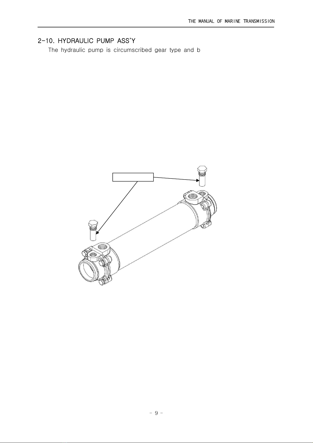
2-10. HYDRAULIC PUMP ASS’Y
The hydraulic pump is circumscribed gear type and bolted on the pump holder.
The pump driving gear is driving block and spline fitted at the end of the
astern shaft, and rotated at the same speed as that of engine, but in the
opposite to engine direction.
2-11. SCREEN FILTER ASS’Y
The screen filter assembly is connected with a suction pipe of the pump inlet
side of filtrating oil and fixed on the bottom side of the case cover with screws.
It is easy to clean by removing the screen filter cover.
Periodic Inspection : Refer to ANNEX I
2-12. OIL COOLER
Oil Cooler is the device that cools the operating oil inside of marine gearbox
and uses the seawater as cooling water. It is bolted on the cooler fixing block
fitted in the case and cools the oil supplied from hydraulic pump and sends to
the secondary oil filter. It uses Aluminum brass pipe which is strong against
corrosion, and applies the Zinc anode.
Periodic Inspection : Refer to ANNEX Ⅰ
ZINC ANODE
THE MANUAL OF MARINE TRANSMISSION
━━━━━━━━━━━━━━━━━━━━━━━━━━━━━━━━━━━━━━━━━━━━━
- 10 -
CHAPTER 3 - PRINCIPLES OF OPERATION
3-1. OVERVIEW
D-I Marine transmission is operating with the hydraulic pressure and must be
operated within the limits of rated load capacity, and has the same capacity
and reduction ratio for the ahead and astern actuation. Therefore it can be
appropriately used in the application of twin engine system.
The clutches are hydraulic multi -plates types and performed by the hydraulic
pressure. The lubrication for the each part is divided into 2 ways, one is
lubricated by force and another by scattering.
* Lubrication by force: the input shaft spline, input coupling oil seal, bearings,
gears, pinion gears, internal steel plates and external sintered plates, clutch
housing gears and etc.
* Lubrication by scattering: bearings, pinion gears, output gear.
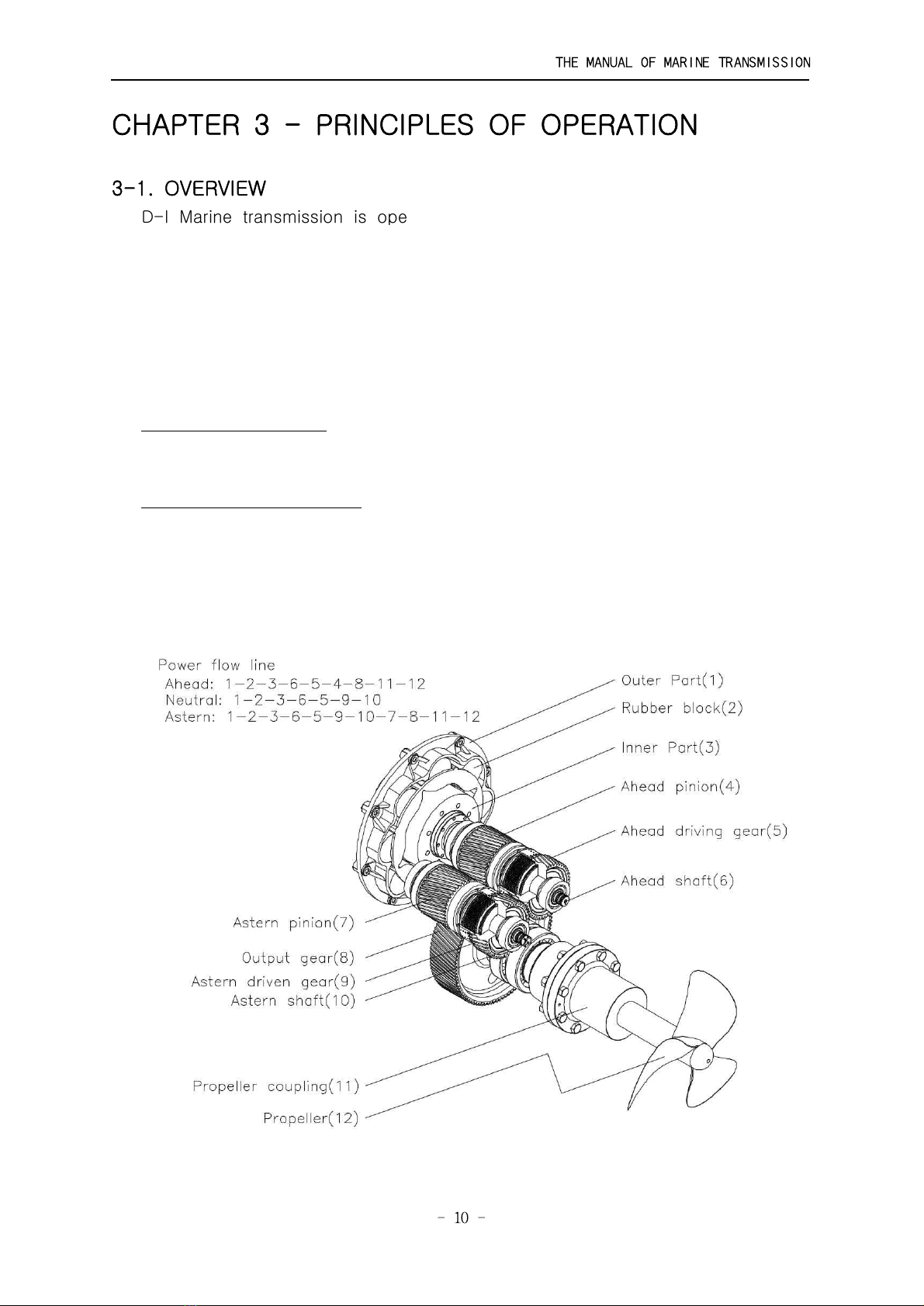
3-2. DIRECTION OF ROTATION
The input shaft is rotated in the same direction as that of engine, and the
output shaft in the opposite direction during ahead actuation but in the same
direction during astern actuation.
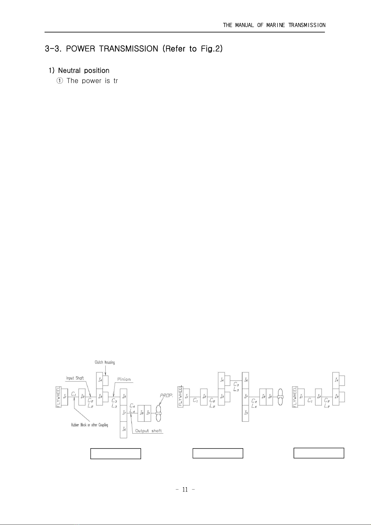
[Fig-2] Drive line system of marine Transmission
THE MANUAL OF MARINE TRANSMISSION
━━━━━━━━━━━━━━━━━━━━━━━━━━━━━━━━━━━━━━━━━━━━━
- 11 -
3-3. POWER TRANSMISSION (Refer to Fig.2)
1) Neutral position
① The power is transmitted from the outer part bolted to engine flywheel to
inner part with rubber blocks in order.
② The inner part transmits the power to input coupling and then the power is
transmitted to input shaft through the input coupling’s spline. At this moment,
the input clutch housing which is shrink-fitted to input shaft also rotates
because the inner teeth of input clutch housing are engaged with outer teeth
of sintered plates.
③ At the same time, the outer teeth of input clutch housing are engaged with
outer teeth of astern clutch housing and inner teeth of astern clutch housing
are engaged with outer teeth of sintered plates, so the astern clutch housing
and sintered plates rotate in the opposite direction of engine.
④ Any rotating parts of marine transmission do not transmit the power in
the neutral condition.
2) Ahead position
① The high-pressure oil from the selector valve pushes the clutch piston in
the input clutch and then steel plates adhere to sintered plates.
② Friction plates rotate in the same direction of input clutch housing.
③ The pinion engaged with steel plates rotates.
④ The power is transmitted to output gear and propulsion force(opposite direction of
engine) occurs.
3) Astern position
① The high-pressure oil from the selector valve pushes the clutch piston in
the astern clutch and then steel plates adhere to sintered plates.
② Friction plates rotate in the same direction of astern clutch housing.
③ The pinion engaged with steel plates rotates.
④ The power is transmitted to output gear and propulsion force(same direction of
engine) occurs.
[Fig-3] Sequence of power transmission
Ahead position Astern position Neutral position

THE MANUAL OF MARINE TRANSMISSION
━━━━━━━━━━━━━━━━━━━━━━━━━━━━━━━━━━━━━━━━━━━━━
- 12 -
CHAPTER 4 - HYDRAULIC SYSTEM
4-1. OVERVIEW
The hydraulic system is shown in Fig.4. The oil contained in the marine
transmission flows into the pump through the oil strainer, and high pressure oil
that is discharged from the gear pump is led to the selector valve body
through the oil cooler, the secondary oil filter and the valve holder. And then,
the oil is regulated to the determined pressure by means of the oil pressure
regulating valve before being led to the valve stem for clutch actuation.
By changing the oil direction of the valve stem, the oil is led to either the
ahead or astern actuation clutch.
[Fig-4] Hydraulic circuit diagram

THE MANUAL OF MARINE TRANSMISSION
━━━━━━━━━━━━━━━━━━━━━━━━━━━━━━━━━━━━━━━━━━━━━
- 13 -
4-2. SELECTOR VALVE GROUP
1) Flow of the pressured oil by operation of the selector valve is shown in
[Fig.5]. The pressured oil discharged from the gear pump is led to the
direction of the arrow "P" in [Fig.6], and then into the hole of the valve
stem.
2) When the selector valve is operated for ahead or astern position, part of the
oil is led to the rear surface of the clutch piston to actuate the clutch, and
another part of it is led to the oil pressure regulating piston through the
orifice of a check valve to raise the oil pressure to the determined pressure
gradually. And the rest of the oil by continuous discharge from the hydraulic
pump, pushes the oil pressure regulating valve and flows through the
passage "L" into the lubricating oil passage to forced-lubricate respective
parts with pressure regulated by means of the lubricating oil pressure
regulating valve.
3) When the selector valve is shifted toward the neutral position, the return
spring of the clutch returns the clutch piston to disconnect the clutch, and
the piston is also returned to lower the pressure down.
[Fig-5] Oil flow path of valve stem - [SEC. A-A of Fig-6]
[Fig-6] SELECTOR VALVE GROUP

THE MANUAL OF MARINE TRANSMISSION
━━━━━━━━━━━━━━━━━━━━━━━━━━━━━━━━━━━━━━━━━━━━━
- 14 -
CHAPTER 5 - INSTALLATION
Installation of marine transmission have an important effect on the function and
performance of the marine transmission.
GAUGE / TOOL SPEC. REMARK
DIAL GAUGE 0.01
MAGNET BASE -
THICKNESS GAUGE 0.01 ~ 1
WRENCHES M16 ~ M32
The Key, which is used for starting a marine engine, should be pulled off
before installing Marine transmission to the Marine engine.
5-1. CHECK POINT BEFORE INSTALLATION
D-I marine transmission is supplied to customers without oil. Thus, before
operation, make sure that the marine transmission is fed with oil SAE #30 and
check the oil amount with oil gauge. (Oil Quantity : check with the name plate)
- MARINE TRANSMISSION Recommended Oil -
5-2. INSTALLATION
The alignment of the engine and the marine transmission is the most important
factor for normal performance and life extension.
1) Engine bed
Use the engine bed made of well-dried rigid wood or steel.
If the engine bed is not rigid, the alignment will be deviated due to the vibration
of the engine or other influence.
2) Supporting
The support brackets for the marine transmission have to be fixed on the engine bed
firmly like the engine mounting. Especially, the bolts of flywheel housing and brackets
(where the arrows point at in the below figure) should be tightened firmly.
Name Manufacturer
Daphne Marine Oil SX30 S-Oil
Delo 1000 Marine 30 GS Caltex
diamond Marine T103(TBN13 SAE#30) MICHANG OIL IND,CO.,LTD.
Exxmar 12TP30 Esso Oil Co., Ltd
Mobilgard 312(SAE#30) Mobil KOREA
Shell Gadinia Oil 30 Showa Shell Oil Co., Ltd
Jomo marines D13 Japan Energy Corporation

THE MANUAL OF MARINE TRANSMISSION
━━━━━━━━━━━━━━━━━━━━━━━━━━━━━━━━━━━━━━━━━━━━━
- 15 -
Bolts for Housing and Brackets of marine transmission should be tightened
firmly. If not, a noise, vibration or breakage of housing can be occurred.
3) Alignment
The alignment of marine transmission's output shaft coupling and the propeller
shaft coupling should be precise and the allowable deviation is as indicated in
the following figures :
The alignment must be made only when the ship is afloat, not in a
dock. In addition, in case of a wooden ship, periodic check should be
made every one or two months since the engine bed may be bent up to
about six months after initial installation, and also a FRP or steel ship
must be checked periodically.
Engine
Shim
Engine
Shim
Bracket
Engine bed
Marine
gearbox

THE MANUAL OF MARINE TRANSMISSION
━━━━━━━━━━━━━━━━━━━━━━━━━━━━━━━━━━━━━━━━━━━━━
- 16 -
CHAPTER 6 - OPERATION
6-1. PREPARATIONS FOR OPERATION
1) Check the whole parts of marine transmission and if the bolts, nuts, etc.
are loosened.
2) Check the oil level with oil level gauge and neutral pressure.
2-1) Check if the neutral pressure(1~5 kgf/㎠) is formed within 30 seconds at
idle RPM after the engine starts up. (If not, just stop the engine and then
check relevant parts)
2-2) After running the engine at idle RPM for 2~3 minutes, stop the engine
and check the oil level in 2~3 minutes.
3) Place the selector valve lever on the neutral position before starting the
engine.
Check the oil amount in marine transmission before operation.
If the oil is not enough, fill it up with oil.
If the neutral pressure is not formed, just stop the engine.
6-2. OPERATION AND STOP
1) Run the engine at idle RPM for about 10 minutes for warming-up.
2) During 10 minutes warming-up, check on oil leakage, abnormal noise,
over-heat, cooling water condition, etc.
3) Check the neutral oil pressure as increasing the engine RPM gradually.
(The clutch oil pressure is 1~5 kgf/㎠ at engine idle RPM in neutral position)
4) Check if the operating oil pressure is normal when operating the marine
transmission in ahead and astern position. (Refer to 1-2 "Specifications")
When decreasing the engine RPM, the operating oil pressure could be
decreased a little bit, however, it is normal.
5) The shifting of selector valve lever to ahead or astern position must be taken
at 50% of rated engine RPM or under.
6) The oil temperature during continuous operation is 50-90℃, but it could be
increased a little bit by frequent ahead and astern shifting.
7) Observe abnormal noises, over-heat, etc. all the time during operation.
If abnormal conditions are found, stop the engine and find out the causes
of them and then take measures to solve them.
8) Be sure to place the selector valve lever on the neutral position before
stopping the engine.
9) To use emergency screws in an emergency
In case that the ahead clutch is slipped or not operated, it can be engaged
mechanically by emergency measures. The ahead clutch has three screws
called emergency screws assembled and it can be engaged by tightening the
screws. If the failure is repairable on the spot, repair it correctly as referring

THE MANUAL OF MARINE TRANSMISSION
━━━━━━━━━━━━━━━━━━━━━━━━━━━━━━━━━━━━━━━━━━━━━
- 17 -
to "Trouble shooting". If it is not repairable on the spot, enter the nearest port
by using the emergency screws and then repair it.
Shifting of selector valve lever to ahead and astern position
must be taken at 50% of rated engine RPM or under.
* How to use the emergency screws
1) First, stop the engine.
2) Remove the valve holder cover shown in [Fig.7].
3) After disassembling the hexagon screw remarked in the [Fig 8], seek the
emergency screws of [Fig 9] by turning the flywheel of engine and tighten
the 3 emergency screws with the 5mm hexagon wrench (Torque: 130kg.cm)
4) Re-assemble the removed hexagon socket screw.
* To make the ahead clutch return to original condition, loosen the emergency
screw again.
To use the emergency screws means that the ahead clutch
is engaged all the time. Therefore, be careful when the
engine starts up because the vessel moves forward once
the engine is on. During a sail, the selector valve must be
placed on the ahead position and the engine should be
operated at 70% of rated engine RPM or under.
When using the emergency screws, fill the marine
transmission with oil till the oil level comes up to center of
astern shaft.
The vessel should slow down before entering the port and
be taken in tow because the astern function does not work
while using the emergency screws.
Table of contents


