6
2). Summary & Features
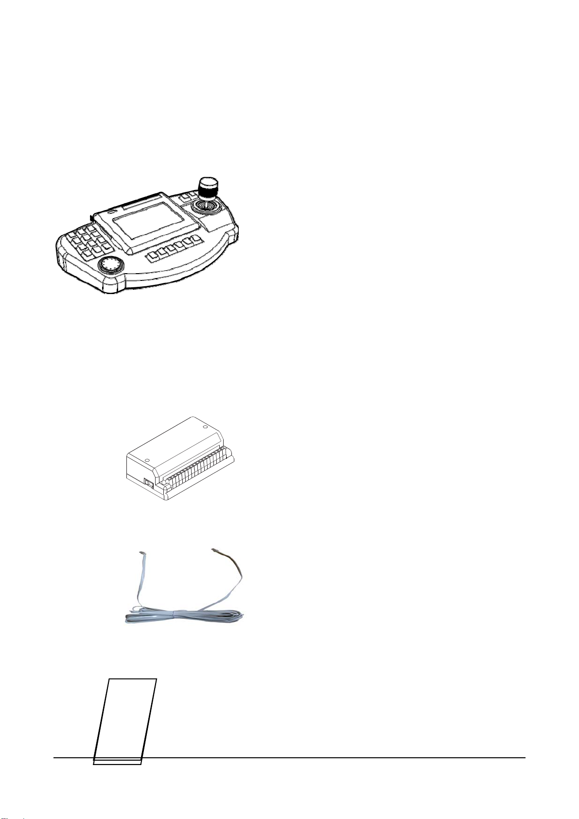
1. Summary
This unit is a multiple CCTV control keyboard enables to control Speed Dome Camera, CCTV
Receiver, Matrix System, DVR, Quad and so on. You can set up a variety of functions of the
speed dome camera and make efficient use of the dome camera for better surveillance by
gearing all kinds of sensors.
This appliance can be used as a Matrix main(sub) keyboard, CCTV Transmitter main(sub)
keyboard at user’s option.
This manual is explaining only about controlling CCTV Transmitter, please refer to the matrix
manual for the detailed use of D-MAX Matrix system.
2. Features
• Locking monitor and camera control.
• Convenient control by 5.5 Inch Touch Screen
• Controls up to 512 cameras.
• Controls maximum 32 monitors (when connecting with matrix, DMX-25632)
• Controls maximum 64 DVR
• Pan/ Tilt/ Zoom controlled by 3-axis joystick.
• Max. 500 Preset widens the surveillance area.
• PAN/ TILT Swing (Auto Pan)
• 12 Group-Tour
• Set and Run the Tour
• Set and Run PTZ Trace.
• Set up on OSD menu of the camera.
• Set and Run Spiral.
• Gearing with alarm receiver unit(controls 512 Sensors)
• Controls DVR with Jog-shuttle (Soon be developed)
• Remote control from Remote Controller
• Users with password only can set up the function.