7
1. Read this manual carefully until you completely understand and follow all
safety and operating instructions.
2. Keep this manual handy so that you may refer to it later whenever any
questions arise. Also note, if you have any questions which cannot be
answered herein, contact the dealer from whom you purchased the product.
3. Always be sure to include this manual when selling, lending, or otherwise
transferring the ownership of this product.
4. Never allow children or anyone unable to fully understand the directions
given in the manual to use the machine.
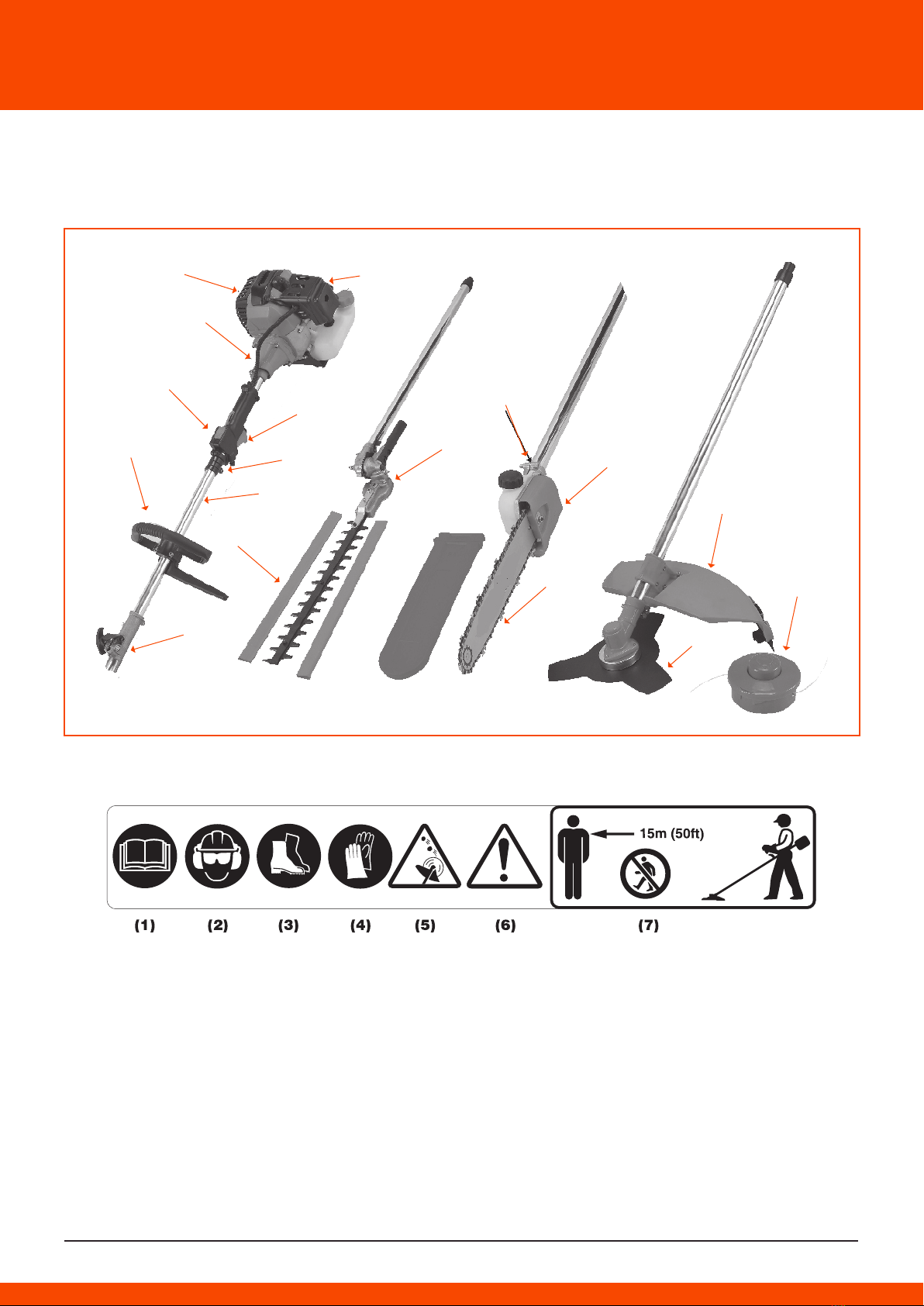
WORKING CONDITION
should wear proper clothing and protective equipment.
(1) Helmet
(2) Ear protectors
(3) Protection goggles or face protector
(4) Thick work gloves
(5) Non-slip-sole work boots
WARNING!
The metallic parts reach high temperatures immediately after stopping
the engine.
3. When replacing the cutting attachment or any other part, or when repla-
cing the oil ar any lubrican!, always be sure to use only authorized products
or prod-ucts which have been certified by your supplier
4. In the event that any part must be replaced or any maintenance or repair
work not described in this manual must be performed, please contact a
representative from the stare nearest ZENOAH autharized servicing dealer
far assistance.
5. Do not use any accessary ar attachment other than those bearing the
ZENOAH mark and recommended for the unit.
6. Under no circumstances should you ever take apart the product ar alter it
in any way. Doing so might result in the product becoming damaged during
operation or the product becoming unable to operate properly.
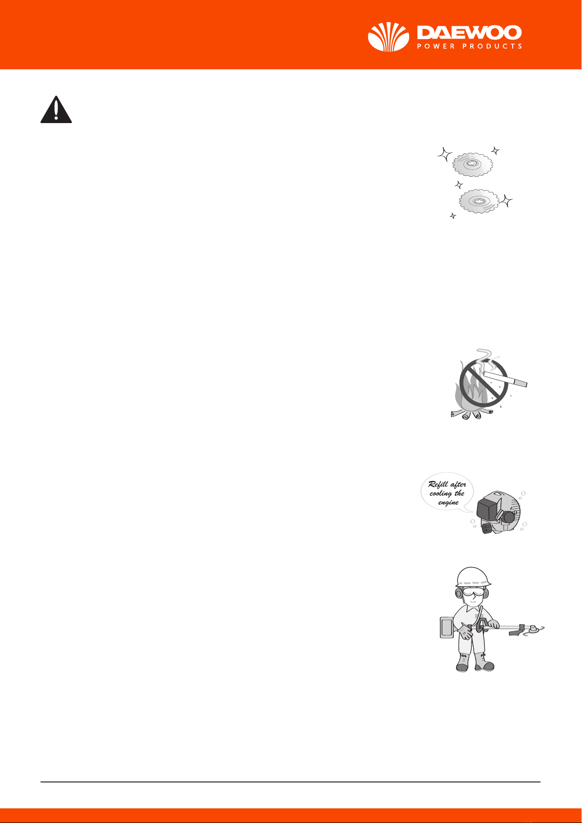
HANDLING FUEL
1. The engine of our 4 in 1 product is designed to run on a mixed fuel, which
contains highly flammable gasoline. Never stare cans of fuel or refill the tank
of the unit in any place where there is a boiler, stove, wood fire, electrical
sparks, welding sparks, or any other source of heat ar fire which might
ignite the fuel.
2. Never smoke while operating the unit or refilling its fuel tank.
3. When refilling the tank, always turn off the engine and allow it to cool
down. Take a careful look around to make sure that there are no sparks or
open llames anywhere nearby befare refueling.
4. Wipe spilled fuel completely using a dry rag if any fuel spillage occurs
during refueling.
5. Alter refueling, screw the fuel cap back tightly onto the fuel tank and then
carry the unit to a spot 3 m or more away from where it was refueled befare
turning on the engine.
TRANSPORTATION
1. When hand-carrying the product, cover over the cutting part if necessary,
lift up the product and carry it paying attention to the blade.
2. Never transpart the product over rough roads over long distances by
vehicle without removing all fuel from the fuel tank. lf doing so, fuel might
leak from the tank during transport.