Daewoo 14C5 User manual

Service Manual
Color Television
CHASSIS : CP-185
Model : 14C5
http : //svc.dwe.co.kr Oct. 2000
DAEWOO ELECTRONICS CO., LTD.
S/M No. : TCP185MEF0
SPECIFICATIONS
14C5
Sound system
Version
TV standard
mono
TF
PAL B/G
Power consumption 14";39W;
Sound Output Power 2.5W (at 60% mod, 10% THD)
3W 8 ohm
75 ohm unbalanced
off-air cannels, S-cable channels and hyperband
Speaker
Teletext system
Aerial input
Channel coverage
frequency synthesiser tuning system
Tuning system
10 pages memory FASTEXT (FLOF or TOP)
version with teletext only
Visual screen size
Channel indication On Screen Display
14": 34 cm
Program Selection 100 programmes
Aux. terminal EURO-SCART : Audio / Video in and Out,
R/G/B in, Slow and Fast swtching, SVHS in.
Audio-Video jack on front of cabinet in common
connection with EURO-SCART.
Headphone jack (3.5mm) on fromt of cabinet
Remote Control Unit R - 40A01

2
CIRCUIT BLOCK DIAGRAM

7
ALIGNMENT INSTRUCTIONS
Microcontroller configuration : Service mode
To switch the TV set into service mode please see instruction below.
1 - Select pr. number 91
2 - Adjust sharpness to minimum and exit all menu.
3 - Quickly press the key sequence : RED - GREEN - menu
To exit SERVICE menu press menu key or Std By key.
In Service Mode press “OK” to stop the microcontroller i.e. the I2C bus is free and the set can be controlled by external equipment.
Press “OK” again to allow the microcontroller to control the set again
Microcontroller configuration :
Tuner Option
System Option
TV set Alignment
1 - G2 alignment
- Set TV in NORMAL I mode
- TV in AV mode without video signal ? Black screen.
- TV preset with WP Red, WP Green and WP Blue equal to 32.
- TV preset with Black R, Black G equal to 8.
-Adjustscreenvolume(onFBT)suchthatthehighestcathodecut-offvoltagemeasuredonCRTboard,isVcut-off±5V.
2 - White balance
- Select a dark picture and adjust Black G and Black R to the desired colour temperature.
- Select a bright picture and adjust WP Red, WP Green, WP Blue to the desired colour temperature.
Option Tuner maker
DW DAEWOO / SAMSUNG
PH1 PHILIPS ( Video processor AGC )
PH2 PHILIPS (tuner internal AGC )
Option System
TF PAL -B/G
TK PAL/SECAM - B/G, D/K (set for Russia)
TU PAL - I/I
TA PAL/SECAM - B/G, SECAM -L/L’
Screen size Vcut-off
14”115 V
20”& 21”125 V

AUDIO
VIDEO

4
Mechanical Exploded View

5
LOC. PART CODE PART NAME PART DESCRIPTION
ZZ110 PTACPWA21C6F ACCESSORYAS DTA-21C6TFF
00100 4850Q00910 BATTERY ROCKETAAAR03/NN
10000 48586A1617A MANUAL ALL
M821 4858213800 BAGPOLY L.D.P.E.T0.5X250X40MILK
ZZ100 48B3740A01 TRANSMITTERREMOCON R-40A01
ZZ120 PTBCSHD616 COVER BACK AS DTP-21C6TFP
M211 4852151601 COVERBACK "HIPS BK 21V1, V4, C6 "
M541 4855415800 S/PLATE 150ARTP/EFILM(C/TV)
M542 4855800022 LABEL SERIAL ART9070X19
ZZ130 PTPKCPA21C6F PACKINGAS DTA-21C6TFP
10 6520010200 STAPLEPIN #3417ALL
20 6520010200 STAPLEPIN #3417ALL
M801 GPBBW3V1112 BOX "DTA-21C6,V4,V1(NEW) "
M811 4858190700 PAD EPS21C6
M821 4858211801 BAGP.E. PEFILMT0.05X1300X1000
ZZ140 PTCACAA21C6FP CABINETAS DTA-21C6TFP
M191 4854943202 BUTTONCONTROL 21C6
M201A 4856013300 SCREWCRT FIXINGAS L-80
M201B 4856215402 WASHERRUBBER 20''
M201C 4856013302 SCREWCRT FIXINGAS L-190
M211A 7172401412 SCREWTAPPING TT2TRS4X14MFZNBK
M211D 7172401412 SCREWTAPPING TT2TRS4X14MFZNBK
M481 4854943203 BUTTONPOWER 21C6
M551 4855538000 DECOSENSOR 21C6
M561 485562140101 MARKBRAND DAEWOO14/20/21/C4/C6
M681 4856812001 TIECABLE NYLON66 DA100
P402A 4850706057 CONNAS ODY-2109
PWC1 4859906210 CORDPOWER FTZ(LOMAXNEWTYPE)
SP01A 7178301011 SCREWTAPPING TT2WAS3X10 MFZN
V901 4859621760C "CRT (THOMSON 21"") " A51EBV13X081(WITH CONN)
ZZ131 58G0000147 COILDEGAUSSING DC-21SF
ZZ132 48519A5310 CRTGROUNDAS 2101S-1015-1P
ZZ200 PTFMSJD616 MASKFRONT AS DTP-21C6TFP
M201 4852071401 MASKFRONT HIPSBK 21C6
ZZ210 PTSPPWA615 SPEAKERAS DTP-14C4TFD
P601A 4850703S50 CONNAS YH025-03+3509=200
SP01 4858314010 SPEAKER SP-5070F013W 8 OHM
ZZ290 PTMPMSA21C6FP PCBMAINMANUAL AS DTA-21C6TFP
10 2193100801 SOLDERBAR SN:PB=63:373PI(NOFLUX)
40 2291050314 FLUXSOLVENT IM-1000
20 2193011101 SOLDERWIRE RS60-1.21.6A
30 2291050617P FLUXSOLDER CF-329D
50 2291140501 WAXCOVER 60G/PC
60 2291051001 FLUX KILLER KFT-7
C315 CEXF2C470C CELECTRO 160V RUS 47MF (13X25) TP
C404 CMYH3C752J CMYLAR 1.6KV7500PFJ(BUP)
C408 CMYE2D274J CMYLAR 200V 0.27MF J (PL)
C415 CEXF2E100V CELECTRO 250V RSS 10MF (10X20) TP
C603 CEXF1C471V CELECTRO 16V RSS 470MF (10X12.5)TP
C801 CL1JB3474K CLINE ACROSS AC250V 0.47MF U/C/SNDF/SV
C805 CEYN2G101P CELECTRO 400V LHS 100MF
C810 CCXB3D102K CCERA 2KVB1000PF K (TAPPING)
C812 CH1AFE472M C CERA AC 4KV4700PFMKXDE1610
C813 CEXF2C101V CELECTRO 160VRSS100MF (16X25) TP
C814 CEXF2C101V CELECTRO 160VRSS100MF (16X25) TP
C823 CEXF1E102V CELECTRO 25VRSS1000MF (13X20) TP
C832 CEXF1E102V CELECTRO 25VRSS1000MF (13X20) TP
C840 CEXF1C222V CELECTRO 16VRSS2200MF(13X25)TP
C841 CEXF1C222V CELECTRO 16VRSS2200MF(13X25)TP
C861 CEXF1E102V CELECTRO 25VRSS1000MF (13X20) TP
C965 CCXB3D102K CCERA 2KVB 1000 PF K (TAPPING)
D403 DBY228---- DIODE BY228
D707 DSML1216W- LED SML1216W
D820 DBYW76---- DIODE BYW76
F801 5FSCB4022R FUSECERA SEMKO F4AH 4A 250V MF51
G900 4SG0D00103 SPARKGAP S-23900V-1.5KV
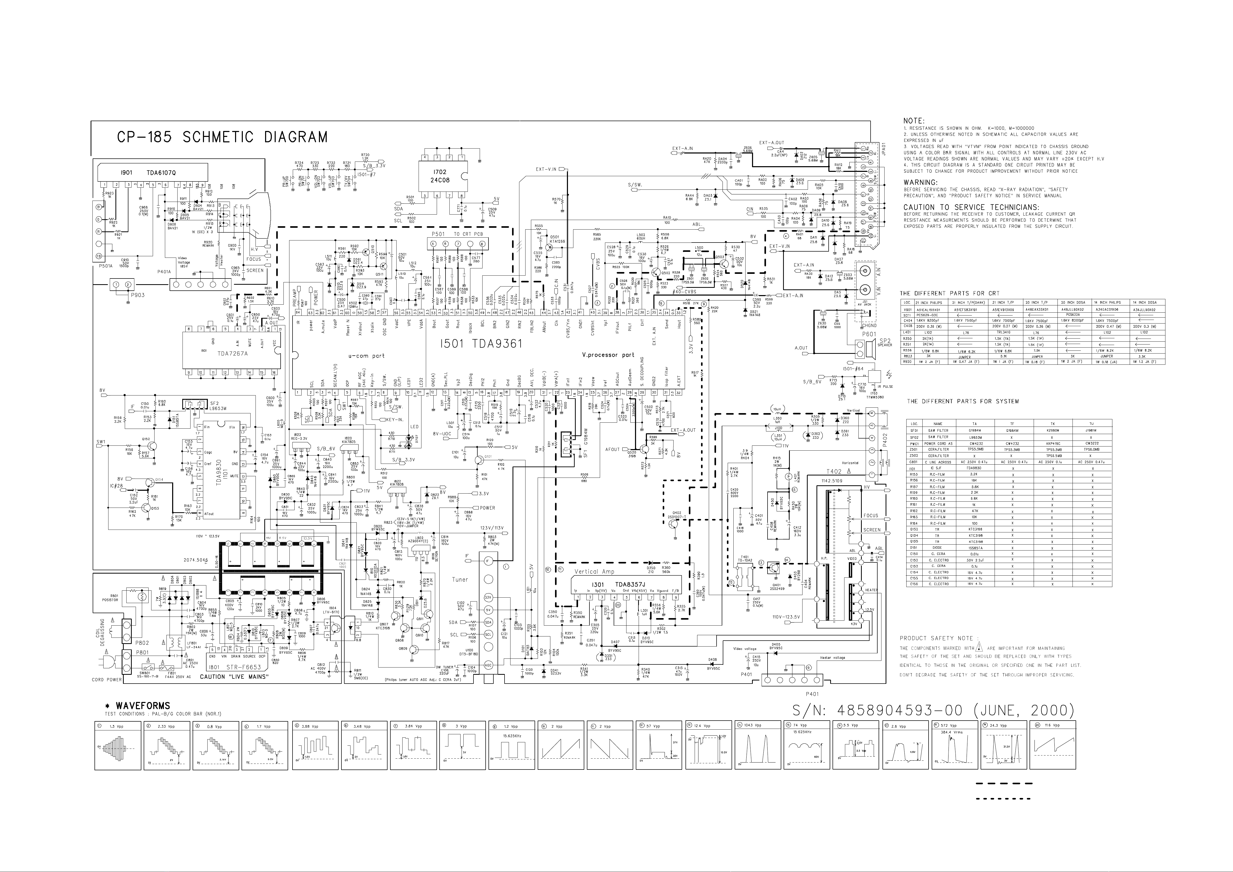
1301 1TDA8357J- ICVERTICAL TDA8357J
I301A 4857025405 HEATSINK A1050P-H24(CP-185)
I301B 7174301011 SCREWTAPPTITE TT2RND3X10MFZN
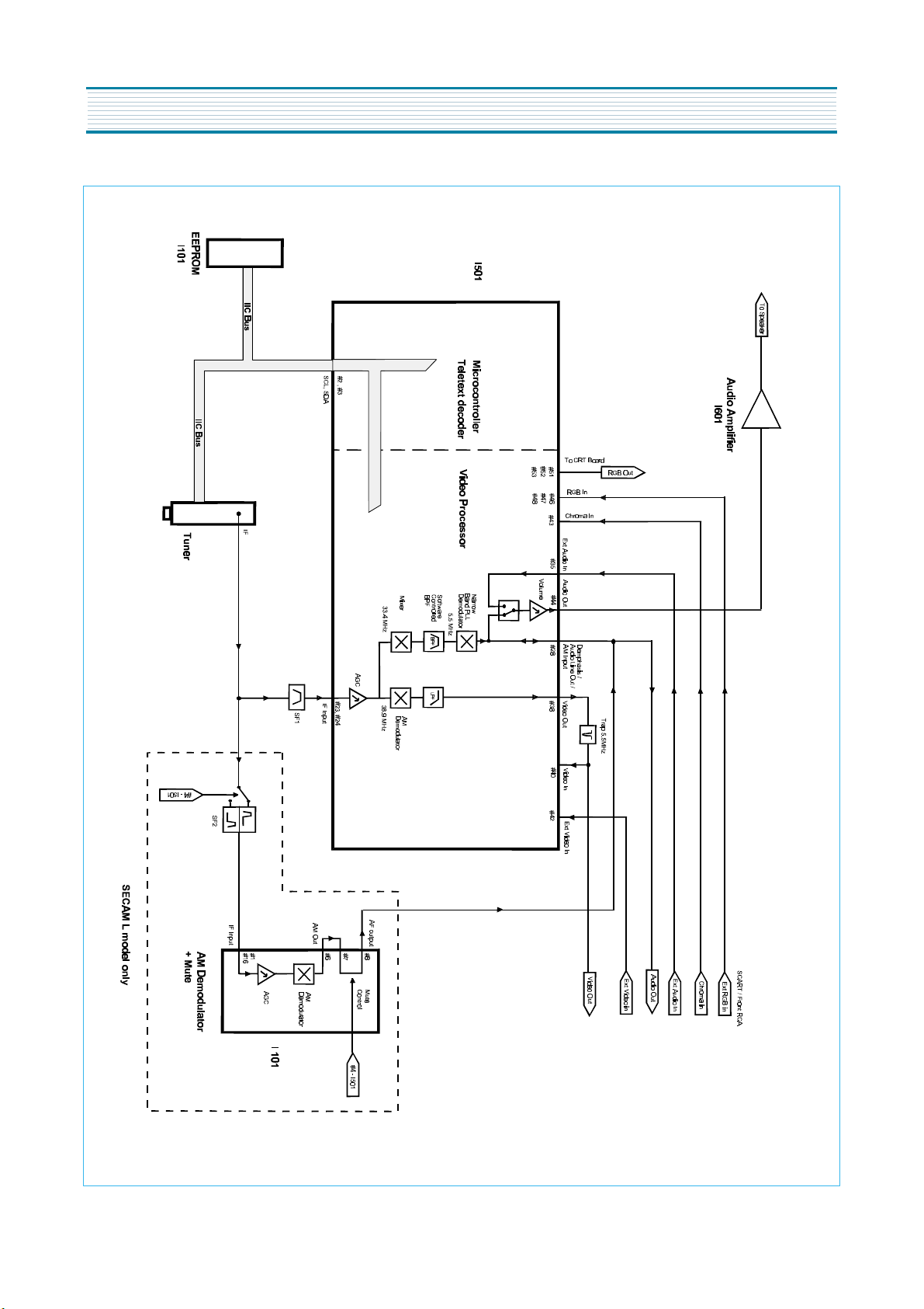
I501 1DW3613DE1 ICMAIN TDA9361/N1/3-DE1
I601 1TDA7267A- ICAMP TDA7267A
I702 1AT24C08PC ICMEMORY AT24C08-10PC
I703 1KRT30---- ICPREAMP KRT30
I801 1STRF6653- ICSMPS STR-F6653
I801A 4857024618 HEATSINK ALEX(I801A)
I801B 7174300811 SCREWTAPPTITE TT2 RND 3X8 MFZN
I804 1LTV817C-- ICPHOTOCOUPLER LTV-817C
I806 1SE110N--- IC SE110N
I810 TX0202DA-- THYRISTOR X0202DA
I820 1KA7805--- ICREGULATOR KA7805
I822 1KA7808--- ICREGULATOR KA7808
I823 1LE33CZ--- ICREGULATOR LE33CZ
I901 1TDA6107Q- ICVIDEO TDA6107Q
I901A 4857031100 HEATSINK A1050P-H24T2.0
I901B 7174301011 SCREWTAPPTITE TT2RND3X10MFZN
JPA1 4859200401 SOCKETRGB SR-21A1(ANGLETYPE)
JS1 4859109950 JACKPINBOARD PH-JB-9710A
L401 58H0000040 COILH-LINEARITY TRL-341G
L802 58C9430599 COILCHOKE AZ-9004Y(94MH)
LF801 5PLF24A1-- FILTERLINE LF-24A1
M351 4853533600 HOLDERLED P.PBK
M791 4857913305 RUBBERCUSHION FRRUBBERSPONGE
P401 4850705N18 CONNECTOR BIC-05T-25T+ULW=400
P402 4859240120 CONNWAFER YFW500-06
P501 4850705N14 CONNECTOR BIC-05T-25T+ULW=500
P601 4859231620 CONNWAFER YW025-03
P801 4859287320 CONNWAFER MKS2822(LOMAXNEW TYPE)
P802 4859242220 CONNWAFER YFW800-02
Q401 T2SD2499-- TR 2SD2499
R305 RS02Y331JS RM-OXIDEFILM 2W330OHMJSMALL
R415 RS02Y102JS RM-OXIDEFILM 2W1KOHM J SMALL
R450 RS02Y103JS RM-OXIDEFILM 2W 10K OHM J SMALL
R801 DPC7R0M290 POSISTOR 96709(PHILIPS)
R802 RS02Y753JS RM-OXIDEFILM 2W 75K OHM J SMALL
R803 RS02Y473JS RM-OXIDEFILM 2W 47K OHM J SMALL
R804 RF02Y338K- RFUSIBLE 2W0.33 OHM K
R808 RS02Y821JS RM-OXIDEFILM 2W820OHMJSMALL
R819 RX07C339JF RCEMENT 7W 3.3 OHM J 15MM 4P
LOC. PART CODE PART NAME PART DESCRIPTION
SERVICE PARTS LIST
R
!
IS RECOMMENDABLE PART FOR STOCK.
IS SAFETY COMPONENT, SO IT MUST BE USED THE SAME COMPONENT.
R
!
Caution
R
R!
!
R
R
!
R!
R
R
R
!
R

5
R920 RF01Y109JA RFUSIBLE 1W1OHMJACURVE
SCT1 4859303530 SOCKETCRT PCS629-03C
SF1 5PG1984M-- FILTERSAW G1984M
SW801 5S40101146 SWPOWERPUSH SS-160-7-B
T401 50D10A2--- TRANSDRIVE TD-10A2
T402 50H0000211 FBT 1142.5109
T801 50M3535A1- TRANSSMPS "2074,5046 "
U100 4859720730 TUNERVARACTOR UV1316/A
X502 5XE12R000E CRYSTALQUARTZ HC-49/U12.00000MHZ 30PPM
Z501 5PYXT5R5MB FILTERCERA XT5.5MB
ZZ200 PTMPJRA21C6FP PCBMAINRADIAL AS DTA-21C6TFP
C101 CEXF1H100V CELECTRO 50VRSS 10MF (5X11) TP
C102 CEXF1H470V CELECTRO 50V RSS 47MF (6.3*11) TP
C106 CEXF1E221V CELECTRO 25V RSS 220MF (8X11.5) TP
C120 CCXB1H102K CCERA 50V B 1000PF K (TAPPING)
C121 CEXF1H100V CELECTRO 50VRSS 10MF (5X11) TP
C305 CEXF1E221V CELECTRO 25V RSS 220MF (8X11.5) TP
C313 CMXM2A104J CMYLAR 100V 0.1MF J TP
C320 CBXF1H104Z CCERA SEMI 50V F 0.1MF Z (TAPPING)
C390 CMXM2A473J CMYLAR 100V0.047MF J TP
C401 CEXF1H470V CELECTRO 50V RSS 47MF (6.3*11) TP
C412 CEXF2C339V CELECTRO 160V RSS 3.3MF (8X16) TP
C414 CMXM2A104J CMYLAR 100V 0.1MF J TP
C417 CMXL2E104K CMYLAR 250V 0.1MF K MEU TP
C418 CCXB1H102K CCERA 50V B 1000PF K (TAPPING)
C420 CCXB2H222K CCERA 500V B 2200PF K (TAPPING)
C500 CEXF1H478V CELECTRO 50V RSS 0.47MF (5X11) TP
C501 CEXF1H100V CELECTRO 50VRSS 10MF (5X11) TP
C502 CEXF1H100V CELECTRO 50VRSS 10MF (5X11) TP
C504 CMXM2A332J CMYLAR 100V 3300PF J TP
C509 CEXF1E470V CELECTRO 25VRSS 47MF (5X11) TP
C511 CMXB1H224J CMYLAR 50VEU0.22MFJ(TP)
C512 CMXB1H224J CMYLAR 50VEU0.22MFJ(TP)
C513 CBXF1H104Z CCERA SEMI 50V F 0.1MF Z (TAPPING)
C514 CEXF1E101V CELECTRO 25V RSS 100MF (6.3X11) TP
C517 CEXF1H109V CELECTRO 50VRSS1MF(5X11) TP
C519 CEXF1H229V CELECTRO 50V RSS 2.2MF (5X11) TP
C522 CEXF1H479V CELECTRO 50V RSS 4.7MF (5*11) TP
C524 CMXM2A104J CMYLAR 100V 0.1MF J TP
C525 CCXB1H102K CCERA 50V B 1000PF K (TAPPING)
C526 CMXM2A104J CMYLAR 100V 0.1MF J TP
C527 CMXM2A473J CMYLAR 100V0.047MF J TP
C528 CEXF1E101V CELECTRO 25V RSS 100MF (6.3X11) TP
C530 CEXF1C101V CELECTRO 16V RSS 100MF (6.3X11) TP
C532 CEXF1H100V CELECTRO 50VRSS 10MF (5X11) TP
C533 CCXB1H102K CCERA 50V B 1000PF K (TAPPING)
C537 CBXF1H104Z CCERA SEMI 50V F 0.1MF Z (TAPPING)
C555 CEXF1C470V CELECTRO 16VRSS 47MF (5X11) TP
C560 CBXF1H104Z CCERA SEMI 50V F 0.1MF Z (TAPPING)
C564 CEXF1E101V CELECTRO 25V RSS 100MF (6.3X11) TP
C565 CBXF1H104Z CCERA SEMI 50V F 0.1MF Z (TAPPING)
C570 CCXB1H472K CCERA 50V B 4700PF K (TAPPING)
C571 CCXB1H821K CCERA 50VB820PFK (TAPPING)
C585 CCXB1H222K CCERA 50V B 2200PF K (TAPPING)
C590 CXCH1H270J CCERA 50V CH 27PF J (TAPPING)
LOC. PART CODE PART NAME PART DESCRIPTION
C591 CXCH1H270J CCERA 50VCH27PF J (TAPPING)
C592 CBXF1H104Z CCERASEMI 50VF0.1MFZ (TAPPING)
C593 CEXF1E101V CELECTRO 25VRSS100MF (6.3X11) TP
C599 CEXF1H229V CELECTRO 50VRSS2.2MF (5X11) TP
C600 CEXF1E101V CELECTRO 25VRSS100MF (6.3X11) TP
C601 CEXF1H108V CELECTRO 50VRSS0.1MF (5X11) TP
C602 CCXF1H103Z CCERA 50VF0.01MF Z (TAPPING)
C650 CEXF1E470V CELECTRO 25V RSS 47MF (5X11) TP
C770 CEXF1C101V CELECTRO 16VRSS100MF (6.3X11) TP
C803 CCXF3A472Z CCERA 1KVF4700PF Z (T)
C804 CCXF3A472Z CCERA 1KVF4700PF Z (T)
C806 CEXF1H330V CELECTRO 50VRSS33MF (6.3X11) TP
C807 CCXF1H473Z CCERA 50VF0.047MF Z (TAPPING)
C808 CEXF1H479V CELECTRO 50VRSS4.7MF (5*11) TP
C820 CCXB3A471K CCERA 1KVB470PFK(T)
C821 CCXB1H102K CCERA 50V B 1000PF K (TAPPING)
C824 CCXB3A471K CCERA 1KVB470PFK(T)
C831 CCXB3A471K CCERA 1KVB470PFK(T)
C835 CEXF1H470V CELECTRO 50V RSS 47MF (6.3*11) TP
C844 CEXF1E101V CELECTRO 25VRSS100MF (6.3X11) TP
C863 CEXF1E101V CELECTRO 25VRSS100MF (6.3X11) TP
C866 CCXB3A471K CCERA 1KVB470PFK(T)
C888 CEXF1C470V CELECTRO 16V RSS 47MF (5X11) TP
C910 CCXB1H561K CCERA 50V B 560PF K (TAPPING)
C968 CMXL2E104K CMYLAR 250V0.1MFK MEU TP
CA04 CEXD1H229F CELECTRO 50VRND2.2MF (5X11) TP
CA05 CCXB1H102K CCERA 50V B 1000PF K (TAPPING)
F801A 4857415001 CLIPFUSE PFC5000-0702
F801B 4857415001 CLIPFUSE PFC5000-0702
Q101 T2SC5343Y- TR 2SC5343Y
Q402 T2SD1207T- TR 2SD1207-T(TAPPING)
Q501 TSTA933Y-- TR STA933-Y
Q502 T2SC5343Y- TR 2SC5343Y
Q503 T2SC5343Y- TR 2SC5343Y
Q510 TSTA933Y-- TR STA933-Y
Q511 TSTA933Y-- TR STA933-Y
Q520 T2SC5343Y- TR 2SC5343Y
Q807 T2SC5343Y- TR 2SC5343Y
Q808 T2SC5343Y- TR 2SC5343Y
Q809 T2SC5343Y- TR 2SC5343Y
Q810 T2SC5343Y- TR 2SC5343Y
Q811 T2SC5343Y- TR 2SC5343Y
SW700 5S50101090 SWTACT SKHV17910A
SW701 5S50101090 SWTACT SKHV17910A
SW702 5S50101090 SWTACT SKHV17910A
SW703 5S50101090 SWTACT SKHV17910A
SW704 5S50101090 SWTACT SKHV17910A
Z603 5PXF1B471M FILTEREMI CFI06B1H470PF
Z605 5PXF1B471M FILTEREMI CFI06B1H470PF
Z606 5PXF1B471M FILTEREMI CFI06B1H470PF
Z630 5PXF1B471M FILTEREMI CFI06B1H470PF
ZZ200 PTMPJAA21C6FP PCBMAINAXIALAS DTA-21C6TFP
10 2TM10006LB TAPEMASKING 3M#232-MAP-C6.2X2000M
20 2TM14006LB TAPEMASKING 3M#2326.0X2000M
A001 4859804593 PCBMAIN T1.6X246X246CP-185
LOC. PART CODE PART NAME PART DESCRIPTION
!
R
!
!
R
R
R
SERVICE PARTS LIST

7
C103 CCZB1H102K CCERA 50V B 1000PF K (AXIAL)
C104 CCZB1H102K CCERA 50V B 1000PF K (AXIAL)
C350 CCZF1H473Z CCERA 50V F 0.047MF Z AXIAL
C351 CCZF1H473Z CCERA 50V F 0.047MF Z AXIAL
C515 CBZR1C222M CCERA Y5R16V2200PFM AXIAL
C516 CBZR1C472M CCERA Y5R16V4700PFM AXIAL
C518 CBZF1H104Z CCERA SEMI 50V F 0.1MF Z (AXIAL)
C520 CCZB1H102K CCERA 50V B 1000PF K (AXIAL)
C521 CCZB1H102K CCERA 50V B 1000PF K (AXIAL)
C523 CCZF1H103Z CCERA 50V F 0.01MF Z
C529 CBZF1H104Z CCERA SEMI 50V F 0.1MF Z (AXIAL)
C531 CCZF1H473Z CCERA 50V F 0.047MF Z AXIAL
C534 CCZF1H223Z CCERA 50V F 0.022MF Z
C535 CCZF1H223Z CCERA 50V F 0.022MF Z
C536 CCZF1H223Z CCERA 50V F 0.022MF Z
C577 CCZB1H561K CCERA 50VB560PF K (AXIAL)
C587 CCZB1H101K CCERA 50VB100PF K (AXIAL)
C588 CCZB1H101K CCERA 50VB100PF K (AXIAL)
C589 CCZB1H101K CCERA 50VB100PF K (AXIAL)
C771 CBZF1H104Z CCERA SEMI 50V F 0.1MF Z (AXIAL)
C809 CCZB1H102K CCERA 50V B 1000PF K (AXIAL)
C830 CBZF1H104Z CCERA SEMI 50V F 0.1MF Z (AXIAL)
C850 CCZB1H821K CCERA 50VB820PF K (AXIAL)
CA01 CCZB1H101K CCERA 50VB100PF K (AXIAL)
CA02 CCZB1H101K CCERA 50VB100PF K (AXIAL)
CA03 CCZB1H101K CCERA 50VB100PF K (AXIAL)
CA10 CCZB1H102K CCERA 50V B 1000PF K (AXIAL)
D101 DBAT85---- DIODE BAT85(TAPPING)
D313 DBYW36---- DIODE BYW36(TAPPING)
D341 DUZ33B---- DIODEZENER UZ-33B
D350 DTZX12C--- DIODEZENER TZX12C(TAPPING)
D360 DTZX22C--- DIODEZENER TZX22C(TAPPING)
D361 DUZ33B---- DIODEZENER UZ-33B
D405 DBYW36---- DIODE BYW36(TAPPING)
D407 DBYW36---- DIODE BYW36(TAPPING)
D408 DBYW36---- DIODE BYW36(TAPPING)
D450 DBYW36---- DIODE BYW36(TAPPING)
D510 DTZX3V9B-- DIODEZENER TZX3V9B
D511 DTZX3V9B-- DIODEZENER TZX3V9B
D520 D1N4148--- DIODE 1N4148(TAPPING)
D521 D1N4148--- DIODE 1N4148(TAPPING)
D591 DTZX2V4A-- DIODEZENER TZX2V4A
D710 DTZX5V1B-- DIODEZENER TZX5V1B(TAPPING)
D801 DBYT51J--- DIODE BYT51J(TAPPING)
D802 DBYT51J--- DIODE BYT51J(TAPPING)
D803 DBYT51J--- DIODE BYT51J(TAPPING)
D804 DBYT51J--- DIODE BYT51J(TAPPING)
D805 DBYW36---- DIODE BYW36(TAPPING)
D806 DBYW36---- DIODE BYW36(TAPPING)
D808 DBYW36---- DIODE BYW36(TAPPING)
D809 DBYW36---- DIODE BYW36(TAPPING)
D810 DBYW36---- DIODE BYW36(TAPPING)
D811 DTZX5V6B-- DIODEZENER TZX5V6B(TAPPING)
D821 DBYW36---- DIODE BYW36(TAPPING)
D822 DTZX9V1B-- DIODEZENER TZX9V1B(TAPPING)
LOC. PART CODE PART NAME PART DESCRIPTION
D824 D1N4148--- DIODE 1N4148(TAPPING)
D825 D1N4148--- DIODE 1N4148(TAPPING)
D830 DBYW36---- DIODE BYW36(TAPPING)
D831 DBYW36---- DIODE BYW36(TAPPING)
D840 D1N4148--- DIODE 1N4148(TAPPING)
D841 D1N4148--- DIODE 1N4148(TAPPING)
D860 DBYW36---- DIODE BYW36(TAPPING)
D904 DBAV21---- DIODE BAV21(TAPPING)
D905 DBAV21---- DIODE BAV21(TAPPING)
D906 DBAV21---- DIODE BAV21(TAPPING)
DA02 DTZX12C--- DIODEZENER TZX12C(TAPPING)
DA03 DTZX5V1B-- DIODEZENER TZX5V1B(TAPPING)
DA04 CBZR1C222M CCERA Y5R 16V 2200PF M AXIAL
DA05 DTZX5V6B-- DIODEZENER TZX5V6B(TAPPING)
DA06 DTZX5V6B-- DIODEZENER TZX5V6B(TAPPING)
DA08 DTZX5V6B-- DIODEZENER TZX5V6B(TAPPING)
DA09 DTZX5V6B-- DIODEZENER TZX5V6B(TAPPING)
DA10 DTZX5V6B-- DIODEZENER TZX5V6B(TAPPING)
DA11 DTZX5V6B-- DIODEZENER TZX5V6B(TAPPING)
DA27 DTZX5V6B-- DIODEZENER TZX5V6B(TAPPING)
J001 85801065GY WIRECOPPER AWG221/0.65 TIN COATING
J002 85801065GY WIRECOPPER AWG221/0.65 TIN COATING
J003 85801065GY WIRECOPPER AWG221/0.65 TIN COATING
J004 85801065GY WIRECOPPER AWG221/0.65 TIN COATING
J005 85801065GY WIRECOPPER AWG221/0.65 TIN COATING
J006 85801065GY WIRECOPPER AWG221/0.65 TIN COATING
J007 85801065GY WIRECOPPER AWG221/0.65 TIN COATING
J008 85801065GY WIRECOPPER AWG221/0.65 TIN COATING
J009 85801065GY WIRECOPPER AWG221/0.65 TIN COATING
J012 85801065GY WIRECOPPER AWG221/0.65 TIN COATING
J013 85801065GY WIRECOPPER AWG221/0.65 TIN COATING
J014 85801065GY WIRECOPPER AWG221/0.65 TIN COATING
J015 85801065GY WIRECOPPER AWG221/0.65 TIN COATING
J016 85801065GY WIRECOPPER AWG221/0.65 TIN COATING
J017 85801065GY WIRECOPPER AWG221/0.65 TIN COATING
J018 85801065GY WIRECOPPER AWG221/0.65 TIN COATING
J019 85801065GY WIRECOPPER AWG221/0.65 TIN COATING
J020 85801065GY WIRECOPPER AWG221/0.65 TIN COATING
J021 85801065GY WIRECOPPER AWG221/0.65 TIN COATING
J022 85801065GY WIRECOPPER AWG221/0.65 TIN COATING
J023 85801065GY WIRECOPPER AWG221/0.65 TIN COATING
J024 85801065GY WIRECOPPER AWG221/0.65 TIN COATING
J025 85801065GY WIRECOPPER AWG221/0.65 TIN COATING
J026 85801065GY WIRECOPPER AWG221/0.65 TIN COATING
J027 85801065GY WIRECOPPER AWG221/0.65 TIN COATING
J028 85801065GY WIRECOPPER AWG221/0.65 TIN COATING
J029 85801065GY WIRECOPPER AWG221/0.65 TIN COATING
J031 85801065GY WIRECOPPER AWG221/0.65 TIN COATING
J032 85801065GY WIRECOPPER AWG221/0.65 TIN COATING
J033 85801065GY WIRECOPPER AWG221/0.65 TIN COATING
J034 85801065GY WIRECOPPER AWG221/0.65 TIN COATING
J035 85801065GY WIRECOPPER AWG221/0.65 TIN COATING
J036 85801065GY WIRECOPPER AWG221/0.65 TIN COATING
J037 85801065GY WIRECOPPER AWG221/0.65 TIN COATING
J038 85801065GY WIRECOPPER AWG221/0.65 TIN COATING
LOC. PART CODE PART NAME PART DESCRIPTION
SERVICE PARTS LIST

8
J040 85801065GY WIRECOPPER AWG221/0.65 TINCOATING
J041 85801065GY WIRECOPPER AWG221/0.65 TINCOATING
J043 85801065GY WIRECOPPER AWG221/0.65 TINCOATING
J044 85801065GY WIRECOPPER AWG221/0.65 TINCOATING
J050 85801065GY WIRECOPPER AWG221/0.65 TINCOATING
L101 5CPZ100K02 COILPEAKING 10UH3.5MM K (LAL02TB)
L301 5CPZ109M04 COILPEAKING 1UH10.5MMM (LAL04TB)
L350 5CPZ109M04 COILPEAKING 1UH10.5MMM (LAL04TB)
L351 85801065GY WIRECOPPER AWG221/0.65 TINCOATING
L500 5CPZ120K02 COILPEAKING 12UH3.5MM K (LAL02TB)
L501 5CPZ100K02 COILPEAKING 10UH3.5MM K (LAL02TB)
L502 5CPZ100K02 COILPEAKING 10UH3.5MM K (LAL02TB)
L510 5CPZ100K02 COILPEAKING 10UH3.5MM K (LAL02TB)
L511 5CPZ100K02 COILPEAKING 10UH3.5MM K (LAL02TB)
L512 5CPZ100K02 COILPEAKING 10UH3.5MM K (LAL02TB)
L600 5MC0000100 COILBEAD MD-5(HC-3550)
L801 5MC0000100 COILBEAD MD-5(HC-3550)
L803 5MC0000100 COILBEAD MD-5(HC-3550)
R101 RD-AZ473J- RCARBON FILM 1/6 47K OHM J
R102 RD-AZ472J- RCARBON FILM 1/6 4.7K OHM J
R103 RD-AZ123J- RCARBON FILM 1/6 12K OHM J
R104 RD-AZ104J- RCARBON FILM 1/6 100K OHM J
R105 RD-AZ392J- RCARBON FILM 1/6 3.9K OHM J
R106 RD-AZ101J- RCARBON FILM 1/6 100 OHM J
R107 RD-AZ101J- RCARBON FILM 1/6 100 OHM J
R120 RD-AZ101J- RCARBON FILM 1/6 100 OHM J
R170 RD-AZ133J- RCARBON FILM 1/6 13K OHM J
R302 RD-2Z159J- RCARBON FILM 1/2 1.5 OHM J
R310 RD-AZ102J- RCARBON FILM 1/6 1K OHM J
R311 RD-AZ102J- RCARBON FILM 1/6 1K OHM J
R340 RD-4Z473J- RCARBON FILM 1/4 47K OHM J
R341 RD-4Z242J- RCARBON FILM 1/4 2.4K OHM J
R350 RN-4Z1501F R METAL FILM 1/41.5K OHM F
R351 RN-4Z1501F R METAL FILM 1/41.5K OHM F
R355 RD-AZ272J- RCARBON FILM 1/6 2.7K OHM J
R356 RD-4Z562J- RCARBON FILM 1/4 5.6K OHM J
R360 RD-4Z564J- RCARBON FILM 1/4 560K OHM J
R390 RD-4Z159J- RCARBON FILM 1/4 1.5 OHM J
R401 RD-4Z272J- RCARBON FILM 1/4 2.7K OHM J
R404 RD-4Z399J- RCARBON FILM 1/4 3.9 OHM J
R420 RD-AZ223J- RCARBON FILM 1/6 22K OHM J
R501 RD-AZ101J- RCARBON FILM 1/6 100 OHM J
R502 RD-AZ101J- RCARBON FILM 1/6 100 OHM J
R505 RD-AZ101J- RCARBON FILM 1/6 100 OHM J
R506 RD-AZ332J- RCARBON FILM 1/6 3.3K OHM J
R507 RD-AZ101J- RCARBON FILM 1/6 100 OHM J
R508 RD-AZ332J- RCARBON FILM 1/6 3.3K OHM J
R509 RD-AZ681J- RCARBON FILM 1/6 680 OHM J
R511 RD-AZ333J- RCARBON FILM 1/6 33K OHM J
R512 RD-AZ101J- RCARBON FILM 1/6 100 OHM J
R513 RD-AZ101J- RCARBON FILM 1/6 100 OHM J
R514 RD-AZ101J- RCARBON FILM 1/6 100 OHM J
R515 RD-AZ153J- RCARBON FILM 1/6 15K OHM J
R516 RD-AZ393J- RCARBON FILM 1/6 39K OHM J
R517 RD-AZ102J- RCARBON FILM 1/6 1K OHM J
LOC. PART CODE PART NAME PART DESCRIPTION
R518 RD-AZ273J- RCARBONFILM 1/6 27K OHM J
R520 RD-AZ183J- RCARBONFILM 1/6 18K OHM J
R521 RD-AZ391J- RCARBONFILM 1/6 390OHMJ
R522 RD-AZ221J- RCARBONFILM 1/6 220OHMJ
R523 RD-AZ331J- RCARBONFILM 1/6 330OHMJ
R524 RD-AZ561J- RCARBONFILM 1/6 560OHMJ
R525 RD-AZ104J- RCARBONFILM 1/6 100K OHM J
R526 RD-4Z479J- RCARBONFILM 1/4 4.7 OHM J
R527 RD-AZ431J- RCARBONFILM 1/6 430OHMJ
R528 RD-AZ221J- RCARBONFILM 1/6 220OHMJ
R530 RD-AZ470J- RCARBONFILM 1/6 47 OHMJ
R531 RD-AZ102J- RCARBONFILM 1/6 1K OHM J
R533 RD-AZ103J- RCARBONFILM 1/6 10K OHM J
R534 RD-AZ102J- RCARBONFILM 1/6 1K OHM J
R535 RD-AZ101J- RCARBONFILM 1/6 100OHMJ
R537 RD-AZ101J- RCARBONFILM 1/6 100OHMJ
R538 RD-AZ101J- RCARBONFILM 1/6 100OHMJ
R539 RD-AZ101J- RCARBONFILM 1/6 100OHMJ
R555 RD-AZ103J- RCARBONFILM 1/6 10K OHM J
R556 RD-AZ682J- RCARBONFILM 1/6 6.8K OHM J
R567 RD-AZ101J- RCARBONFILM 1/6 100OHMJ
R570 RD-4Z102J- RCARBONFILM 1/4 1K OHM J
R571 RD-AZ432J- RCARBONFILM 1/6 4.3K OHM J
R572 RD-AZ122J- RCARBONFILM 1/6 1.2K OHM J
R573 RD-AZ272J- RCARBONFILM 1/6 2.7K OHM J
R575 RD-AZ123J- RCARBONFILM 1/6 12K OHM J
R580 RD-AZ561J- RCARBONFILM 1/6 560OHMJ
R585 RD-AZ224J- RCARBONFILM 1/6 220K OHM J
R586 RD-AZ221J- RCARBONFILM 1/6 220OHMJ
R587 RD-AZ101J- RCARBONFILM 1/6 100OHMJ
R588 RD-AZ101J- RCARBONFILM 1/6 100OHMJ
R589 RD-AZ101J- RCARBONFILM 1/6 100OHMJ
R591 RD-AZ221J- RCARBONFILM 1/6 220OHMJ
R592 RD-AZ103J- RCARBONFILM 1/6 10K OHM J
R593 RD-AZ103J- RCARBONFILM 1/6 10K OHM J
R594 RD-AZ103J- RCARBONFILM 1/6 10K OHM J
R595 RD-AZ473J- RCARBONFILM 1/6 47K OHM J
R596 RD-AZ302J- RCARBONFILM 1/6 3K OHM J
R597 RD-AZ153J- RCARBONFILM 1/6 15K OHM J
R598 RD-AZ153J- RCARBONFILM 1/6 15K OHM J
R599 RD-AZ221J- RCARBONFILM 1/6 220OHMJ
R601 RD-4Z432J- RCARBONFILM 1/4 4.3K OHM J
R602 RD-AZ332J- RCARBONFILM 1/6 3.3K OHM J
R610 RD-AZ332J- RCARBONFILM 1/6 3.3K OHM J
R710 RD-AZ431J- RCARBONFILM 1/6 430OHMJ
R711 RD-AZ431J- RCARBONFILM 1/6 430OHMJ
R713 RD-AZ201J- RCARBONFILM 1/6 200OHMJ
R720 RD-AZ122J- RCARBONFILM 1/6 1.2K OHM J
R721 RD-AZ181J- RCARBONFILM 1/6 180OHMJ
R722 RD-AZ221J- RCARBONFILM 1/6 220OHMJ
R723 RD-AZ331J- RCARBONFILM 1/6 330OHMJ
R724 RD-AZ471J- RCARBONFILM 1/6 470OHMJ
R805 RD-2Z100J- RCARBONFILM 1/2 10 OHMJ
R806 RD-4Z472J- RCARBONFILM 1/4 4.7K OHM J
R807 RD-2Z272J- RCARBONFILM 1/2 2.7K OHM J
LOC. PART CODE PART NAME PART DESCRIPTION
SERVICE PARTS LIST

9
R810 RD-4Z102J- RCARBON FILM 1/4 1K OHM J
R811 RC-2Z565KP RCARBON COMP 1/2 5.6M OHM K
R817 RD-AZ473J- RCARBON FILM 1/6 47K OHM J
R820 RD-AZ102J- RCARBON FILM 1/6 1K OHM J
R821 RD-4Z102J- RCARBON FILM 1/4 1K OHM J
R823 RD-4Z512J- RCARBON FILM 1/4 5.1K OHM J
R829 RD-AZ223J- RCARBON FILM 1/6 22K OHM J
R830 RD-AZ332J- RCARBON FILM 1/6 3.3K OHM J
R840 RD-4Z220J- RCARBON FILM 1/4 22 OHM J
R841 RD-2Z479J- RCARBON FILM 1/2 4.7 OHM J
R850 RD-2Z479J- RCARBON FILM 1/2 4.7 OHM J
R855 RD-4Z185J- RCARBON FILM 1/4 1.8M OHM J
R870 RD-4Z222J- RCARBON FILM 1/4 2.2K OHM J
R888 RD-AZ103J- RCARBON FILM 1/6 10K OHM J
R910 RD-AZ101J- RCARBON FILM 1/6 100 OHM J
R911 RD-AZ101J- RCARBON FILM 1/6 100 OHM J
R912 RD-AZ101J- RCARBON FILM 1/6 100 OHM J
R913 RC-2Z102K- RCARBON COMP 1/2 1K OHM K
R914 RC-2Z102K- RCARBON COMP 1/2 1K OHM K
R915 RC-2Z102K- RCARBON COMP 1/2 1K OHM K
LOC. PART CODE PART NAME PART DESCRIPTION
R921 RD-AZ102J- RCARBONFILM 1/6 1K OHM J
R922 RD-AZ102J- RCARBONFILM 1/6 1K OHM J
R923 RD-AZ102J- RCARBONFILM 1/6 1K OHM J
RA01 RD-AZ680J- RCARBONFILM 1/6 68 OHMJ
RA02 RD-AZ101J- RCARBONFILM 1/6 100OHMJ
RA03 RD-AZ101J- RCARBONFILM 1/6 100OHMJ
RA04 RD-AZ101J- RCARBONFILM 1/6 100OHMJ
RA05 RD-AZ103J- RCARBONFILM 1/6 10K OHM J
RA06 RD-AZ750J- RCARBONFILM 1/6 75 OHMJ
RA08 RD-AZ750J- RCARBONFILM 1/6 75 OHMJ
RA09 RD-AZ750J- RCARBONFILM 1/6 75 OHMJ
RA10 RD-AZ101J- RCARBONFILM 1/6 100OHMJ
RA11 RD-AZ183J- RCARBONFILM 1/6 18K OHM J
RA12 RD-AZ183J- RCARBONFILM 1/6 18K OHM J
RA16 RD-AZ680J- RCARBONFILM 1/6 68 OHMJ
RA19 RD-AZ750J- RCARBONFILM 1/6 75 OHMJ
RA20 RD-AZ473J- RCARBONFILM 1/6 47K OHM J
RA30 RD-AZ183J- RCARBONFILM 1/6 18K OHM J
RA44 RD-AZ682J- RCARBONFILM 1/6 6.8K OHM J
LOC. PART CODE PART NAME PART DESCRIPTION
!
SERVICE PARTS LIST

10
SERVICE PAARTS LIST
THE DIFFERENT PARTS FOR SYSTEM CP-185
OC A E TA T T TU
SF01 SAW FILTER G1984M G1984M K2960M J1981M
SF02 SAW FILTER L9653M XXX
PWC1 POWER CORD AS CW4232 CW4232 KKP419C CW3222
Z501 CERA FILTER TP5.5MB TP5.5MB TP5.5MB TPS6.0MB
Z502 CERA FILTER TP6.5MB XXX
C801 C LINE ACROSS AC 250V 0.47 AC 250V 0.47 AC 250V 0.47 AC 250V 0.47
I101 IC IF TDA9830 XXX
R153 R.C.-FILM 2.2K XXX
R156 R.C.-FILM 16K XXX
R157 R.C.-FILM 5.6K XXX
R159 R.C.-FILM 2.2K XXX
R160 R.C.-FILM 6.8K XXX
R161 R.C.-FILM 1K XXX
R162 R.C.-FILM 47K XXX
R163 R.C.-FILM 10K XXX
R164 R.C.-FILM 100 XXX
Q152 TR KTC3198 XXX
Q154 TR KTC3198 XXX
Q155 TR KTC3198 XXX
D151 DIODE 1SS85UA XXX
C150 C.CERA 0.01 XXX
C152 C. ELECTRO 50V 2.2F XXX
C153 C.CERA 0.1 XXX
C154 C. ELECTRO 16V 4.7 XXX
C155 C. ELECTRO 16V 4.7 XXX
C156 C. ELECTRO 16V 4.7 XXX

11
SERVICE PARTS LIST
THE DIFERENT PARTS FOR CRT
LOC. "21"" PHILIPS" "21"" T/P (DARK)" "21"" T/P" "20"" T/P" "20"" DOSA" "14"" PHILIPS"
14"" CHUNGHWA"
"14"" DOSA" "14"" EKRANAS"
V901 A51EAL155X01 A51EFS83X191 A51EVB13X09 A48EAX33X01 A48JLL90X02 A34EAC01X06
A34AGT14X71 A34JLL90X02 A33LPE02X01
4859607660 4859629360C 4859621760C 4859611260N 4859629260 4859608640
SCT1 PCS629-03C PCS629-03C PCS629-03C PCS629-03C PCS633A PCS633A PCS634A PCS629-03C
4859303530 4859303530 4859303530 4859303530 4859303430 4859303430 4859303430 4859303530
C404 1.6KV 8200pF 1.6KV 7500pF 1.6KV 7500pF 1.6KV 7500pF 1.6KV 8200pF 1.6KV 7500pF 1.6KV 7500pF 1.6KV 7500pF
CMYT3C822J CMYT3C752J CMYT3C752J CMYT3C752J CMYT3C822J CMYT3C752J CMYT3C752J CMYT3C752J
C408 200V 0.36 (M) 200V 0.36 (M) 200V 0.27 (M) 200V 0.36 (M) 200V 0.36 (M) 200V 0.47 (M) 200V 0.3 (M) 200V 0.36 (M)
CMYT2D364J CMYT2D364J CMYT2D274J CMYT2D364J CMYT2D364J CMYT2D474J CMYT2D304J CMYT2D364J
L401 L102 L76 TRL341G L76 L76 L102 L102 L102
58H0000016 58H0000020 58H0000040 58H0000020 58H0000020 58H0000016 58H0000016 58H0000016
R350 2K (1%) 2K (1%) 1.5K (1%) 1.5K (1%) 1.5K (1%) 1.5K (1%) 1.5K (1%) 1.5K (1%)
RN-4Z2001F RN-4Z2001F RN-4Z1501F RN-4Z1501F RN-4Z1501F RN-4Z1501F RN-4Z1501F RN-4Z1501F
R351 2K (1%) 2K (1%) 1.5K (1%) 1.5K (1%) 1.5K (1%) 1.5K (1%) 1.5K (1%) 1.5K (1%)
RN-4Z2001F RN-4Z2001F RN-4Z1501F RN-4Z1501F RN-4Z1501F RN-4Z1501F RN-4Z1501F RN-4Z1501F
R556 1/6W 6.8K 1/6W 6.2K 1/6W 6.8K 1/6W 7.5K 1/6W 7.5K 1/6W 8.2K 1/6W 8.2K 1/6W 8.2K
RD-AZ682J- RD-AZ682J- RD-AZ682J- RD-AZ752J- RD-AZ752J- RD-AZ822J- RD-AZ822J- RD-AZ822J-
R823 3K JUMPER 5.1K JUMPER 3K JUMPER 3.3K JUMPER
RD-4Z302J- 85801065GY RD-4Z512J- 85801065GY RD-4Z302J- 85801065GY RD-4Z512J- 85801065GY
R920 1W 2 JA (F) 1W 0.47 JA (F) 1W 1 JA (F) 1W 0.18 JA (F) 1W 2 JA (F) 1W 0.18 JA (F) 1W 1.2 JA (F) 1W 0.18 JA (F)
RF01Y200JA RF01Y478JA RF01Y100JA RF01Y188JA RF01Y200JA RF01Y188JA RF01Y129JA RF01Y188JA

12
FUNCTIONAL DESCRIPTION OF VIDEO PROCESSOR Vision IF amplifier
The vision IF amplifier can demodulate signals with positive and negative modulation. The PLL demodulator is completely
alignment-free.
The VCO of the PLL circuit is internal and the frequency is fixed to the required value by using the clock frequency of the
µ
-Controller/Teletext decoder as a reference. The setting of the various frequencies is made by the controlling software in
subaddress 27H (33.9 MHz for system L’ and 38.9
MHz for all other systems). Because of the internal VCO, the IF circuit
has a high immunity to EMC interference.
1. IF demodulator and audio amplifier
The FM demodulator is realised as a narrow band PLL with external loop filter, which provides the necessary selectivity
withoutusing an extra bandpassfilter.To obtain good selectivityalinearphasedetector and aconstantinputsignalampli-
tude are required. For this reason the intercarrier signal is internally supplied to the demodulator via a gain controlled
amplifier and AGC circuit. The nominal frequency of the demodulator is set via a gain controlled amplifier and AGC circuit.
The nominal frequency of the demodulator is tuned to the required frequency (5.5 / 6.0 / 6.5 MHz) by means of a calibra-
tion circuit which uses the clock frequency of the microcontroller as a reference. Selection of the required frequency is
done by the controlling software.
Video switches
The video switch has one input for an external CVBS or Y/C signal. The selected CVBS signal can be supplied to pin 38,
the IF video output. The selection between both signals is realised by the controlling software in subaddress 22H.
The video ident circuit is connected to the selected signal. This ident circuit is independent of the synchronisation.
Synchronisation circuit
The IC contains separator circuits for the horizontal and vertical sync pulses and a data-slicing circuit which extracts the
digital teletext data from the analogue signal.
The horizontal drive signal is obtained from an internal VCO which is running at a frequency of 25 MHz. This oscillator is
stabilised to this frequency by using a 12 MHz signal coming from the reference oscillator of the
µ
-Controller/Teletext
decoder.
Thehorizontal drive isswitchedonand off via thesoftstart/stopprocedure. This function isrealised by meansof variation
of the TON of the horizontal drive pulses.
FUNCTIONAL DESCRIPTION
APPENDIX

13
FUNCTIONAL DESCRIPTION
The vertical synchronisation is realised by means of a divider circuit. The vertical ramp generator needs an external resistor
and capacitor. For the vertical drive a differential output current is available. The outputs are DC coupled to the vertical output
stage.
The following geometry parameters can be adjusted:
•
Horizontal shift
•
Vertical amplitude
•
Vertical slope
•
S-correction
•
Vertical shift
Chroma and luminance processing
The chroma band-pass and trap circuits (including the SECAM cloche filter) are realised by means of gyrators and are tuned to
therightfrequencybycomparing thetuningfrequency withthereference frequencyofthe colourdecoder. Theluminance delay
line and the delay cells for the peaking circuit are also realised with gyrators. The circuit contains a black stretcher function
which corrects the black level for incoming signals which have a difference between the black level and the blanking level.
Colour decoder
The ICs can decode PAL, NTSC and SECAM signals. The PAL/NTSC decoder does not need external reference crystals but
hasan internalclock generatorwhichis stabilisedtothe requiredfrequency byusingthe 12MHz clocksignalfrom thereference
oscillator of the
µ
-Controller/Teletextdecoder.
The Automatic Colour Limiting (ACL) circuit (switchable via the ACL bit in subaddress 2OH) prevents oversaturation occurring
when signals with a high chroma-to-burst ratio are received. The ACL circuit is designed such that it only reduces the chroma
signal and not the burst signal. This has the advantage that the colour sensitivity is not affected by this function.
SOFTWARE CONTROL
The CPU communicates with the peripheral functions using Special function Registers (SFRS) which are addressed as RAM
locations. The registers for the Teletext decoder appear as normal SFRs in the
µ
-Controller memory map and are written to
these functions by using a serial bus. This bus is controlled by dedicated hardware which uses a simple handshake system for
software synchronisation.
For compatibility reasons and possible re-use of software blocks, the TV processor is controlled by I2C bus. The TV processor
control registers cannot be read. Only the status registers can be read ( Read address 8A ).
The SECAM decoder contains an auto-calibrating PLL demodulator which has two references, via the divided 12 MHz refer-
ence frequency (obtained from the
µ
-Controller) which is used to tune the PLL to the desired free-running frequency and the
bandgap reference to obtain the correct absolute value of the output signal. The VCO of the PLL is calibrated during each ver-
tical blanking period, when the IC is in search or SECAM mode.
The base-band delay line (TDA 4665 function) is integrated. This delay line is also active during NTSC reception, to obtain a
good suppression of cross colour effects. The demodulated colour difference signals are internally supplied to the delay line.
APPENDIX

14
RGB output circuit and black-current stabilisation
IntheRGB control circuit the signal is controlledoncontrast,brightness and saturation. The ICs have a linearinputforexternal
RGB signals. The signals for OSD and text are internally supplied to the control circuit. The output signal has an amplitude of
about 2 Volts black-to-white at nominal input signals and nominal settings of the various controls.
To obtain an accurate biasing of the picture tube the 'Continuous Cathode Calibration’system has been included in these ICs.
A black level off set can be made with respect to the level which is generated by the black current stabilisation system. In this
way different colour temperatures can be obtained for the bright and the dark part of the picture.
The black current stabilisation system checks the output level of the 3 channels and indicates whether the black level of the
highest output is in a certain window or below or above this window. This indication is read from the status byte 01 and is used
for automatic adjustment of the Vg2
voltage during the production of the TV receiver.
During switch-off of the TV receiver a fixed beam current is generated by the black current control circuit. This current ensures
that the picture tube capacitance is discharged. During the switch-off period the vertical deflection is placed in an overscan
position so that the discharge is not visible on the screen.
2. IF
The TDA9361/TDA9381 has an alignment free IF PLL demodulator. The fully integrated oscillator is automatically calibrated,
using the 12 MHz crystal as a frequency reference. The IF frequency is simply set in TV-Processor by I2C bus.
TheAFCinformation is available via I2Cbusfromthe TV-Processor status bytes. Thecontrollingsoftwareuses this information
for tuner frequency tracking ( automatic following ). The AFC window is typically 125Khz wide. The minimum frequency step of
the tuner is 62.5 kHz.
This AFC function is disabled when a program is tuned using the direct frequency entry or after fine tuning adjustment. There-
fore it is recommended to tune a channel with the TV search function ( manual or ATSS ) or by using the direct channel entry to
enable the Automatic Frequency Control.
SAW filters
TF TK TU TA
SF01 G1984M K2960M J1981M G1984M
SF02 ---L9653M
Ref. Standard Features
G1984M B/G
- IF filter for Intercarrier Applications
- TV IF filter with Nyquist slope and sound shelf.
- High colour carrier level
- Reduced group delay predistortion as compared with standard B/G,
half
K2960M B/G - D/K - IF filter for Intercarrier Applications
- TV IF filter with Nyquist slope and sound shelf.
J1981M I
- IF filter for Intercarrier Applications
- TV IF filter with Nyquist slope and sound shelf.
- High colour carrier level
- Constant group delay
L9653M L / L’ - Switchable sound filter
APPENDIX
FUNCTIONAL DESCRIPTION

15
ForSECAM L and L’the TDA9361/TDA9381 is switched to positive modulation via I2C bus. SECAM L’ transmission onlyoccur
in VHF band I and have their picture and sound carrier interchanged, compared to SECAM L and PAL B/G channels. For
SECAM L’the picture carrier is situated at 33.9 MHz and the AM sound carrier at 40.40 MHz. The IF PLL reference is tuned
from 38.9 to 33.9 MHz, this is done via I2C Bus and the SIF filter is switched from channel 2 to channel 1; this is done by pin 4
of TDA 9361.
The tuner AGC time constant is slower for positive than for negative modulation, because the TDA9361 reduces its AGC cur-
rent.Tomake the AGC time constant even sloweranextraseries resistor R103 is added. To preventIFoverloadwhen jumping
from a very strong transmitter to a weak transmitter a diode D101 has been added
************************************************************************************************************************************************
The SAW filter ( SF1 ) has a double Nyquist slope at 38.9 MHz and 33.9 MHz needed for this multistandard application.
The disadvantage of this choice is that a 5.5 MHz trap filter ( Z501 ) is needed to suppress the residual sound carrier in the
video for B/G signals.
************************************************************************************************************************************************
3. Source switching
Video :
The TDA9361/TDA9381 has only one external video input. The SCART video in pin (#20) is connected to the front RCA video
input.
The controlling software via I2C bus selects the signal source :
- Video signal from tuner ( Pin 40 ).
- External video.
- External SVHS from SCART.
The sound source switching is done in the video processor part and in the AM demodulator by the
µ
-Controller via I2C
bus.
The video processor pin 28 has multiple functions and provides in this application
- Deemphasis time constant
- Audio monitor output
- External AM input
- Deemphasis time constant : The time constant is given by the capacitor C504, needed to obtain the 54
µ
s time constant
for standard PAL signal.
- Audio monitor output : the nominal output signal is 500 mVrms, for all standards. The signal is also internally connected
throughtotheaudioswitch.ThissignalisnotcontrolledbythevolumesettingandcanbeusedforSCARTaudiooutput.
The signal is buffered to avoid influencing the deemphasis time constant and to adjust the output level.
- External AM input : By software the deemphasis pin can be converted into an input pin. External AM signal for SECAM
L/L’ is directly connected to this pin. In this configuration the FM sound is internally muted, DC level remains at 3Vdc.
An external sound signal of 500mVrms is applied to pin 35 via a coupling capacitor. The input impedance of this pin is
25K
Ω
typical. Switching between internal FM, external AM or external audio from SCART is controlled internally by soft-
ware.
FUNCTIONAL DESCRIPTION
APPENDIX

16
Fast R, G, B insertion : The external R, G, B insertion needs a fast switching and cannot be controlled by the software (
instruction cycle of 1
µ
sec ). The fast switching pin 16 of SCART is directly connected to the TV processor pin 45 ( Fast
blankinginput ). The display is synchronised with the selected videosource, i.e. toget stable R,G, B signal insertion they
must be synchronised with the selected video source.
4.
µ
-Controller I/O pin configuration and function
The I/O pins of the
µ
-Controller can be configured in many ways. All port functions can be individually programmed by the con-
trolling software.
Each I/O port pin can be individually programmed in these configurations :
Open drain
In this mode, the port can function as input and output. It requires an external pull-up resistor. The maximum allowable supply
voltage for this pull up resistor is +5V.
So in this mode it is possible to interface a 5 Volt environment like I2C while the
µ
-Controller has a 3.3 Volt supply.
Push-Pull
Thepush pullmodecan beusedfor outputonly.Both sinkingandsourcing isactive, whichleads tosteep slopes.The levelsare
0 and Vddp, the supply voltage 3.3Volts.
High impedance
This mode can be used for input only operation of the port.
Special port for LED
Pin10 and 11 have the same functionality as the general I/O pins but in addition, their current source and sink capacity is 8 mA
instead of 4 mA. These pins are used for driving LED’s via a series current limiting resistor.
µ
-Controller I/O pin configuration and function table
pin name configuration description
Stand by TV ON
1n.u. High impedance High impedance not used
2SCL Open Drain Open Drain Serial clock line
3SDA Open Drain Open Drain Serial data line
4SECAM L’High impedance Push Pull / High imped-
ance SIF filter switching + AM/FM
switching
5OCP High impedance High impedance Over Current Protection (
Switch the set OFF if the volt-
age on this pin is <2.3V )
6RF AGC in High impedance High impedance UsedduringATSSto measure
RF signal level.
7Key in High impedance High impedance Local keyboard input
8S/SW High impedance High impedance external video switch
10 Red LED High impedance Open Drain
11 Green LED Open Drain High impedance
62 Audio mute Push Pull High impedance
APPENDIX
FUNCTIONAL DESCRIPTION

17
5. SECAM L/L’ sound switching circuit.
The microcontroller pin 4 is a three levels output. The voltage and configuration of this port is described below :
In FM mode the microcontroller is internally grounded to pin 4. The TDA9830 output is muted
6. Sound amplification
Thedevice TDA7267A is amonoaudio amplifier inpowerDIPpackage specially designed forTVapplication. Thanks to thefully
complementary output configuration the device delivers a rail to rail voltage swing without need of bootstrap capacitors. No
external heat sink is needed as the Cu ground plane of the PCB is used as heat dissipation.
7. Vertical deflection
The vertical driver circuit is a bridge configuration. The deflection coil is connected between the output amplifiers, which are
driven in phase opposition. The differential input circuit is voltage driven. The input circuit is especially intended for direct con-
nection to driver circuits which deliver symmetrical current signals, but is also suitable for asymmetrical currents. The output
current of these devices is converted to voltages at the input pins via resistors R350 and R351. The differential input voltage is
compared with the output current through the deflection coils measured as voltage across R302, which provides internal feed-
back information. The voltage across R302 is proportional to the output current.
Flyback voltage
Theflybackvoltageis determined by an additional supply voltage V
fb
.Theprincipleof operation with two supply voltages (class
G) makes it possible to fix the supply voltage Vp optimum for the scan voltage and the second supply voltage V
fb
optimum for
the flyback voltage. Using this method, very high efficiency is achieved. The supply voltage V
fb
is almost totally available as fly-
back voltage across the coil, this being possible due to the absence of a coupling capacitor.
Protection
The output circuit has protection circuits for :
- Too high die temperature
- overvoltage of output stage A
Guardcircuit
The guard signal is not used by the TDA9361/ TDA9381 to blank the screen in case of a fault condition.
Damping resistor
For HF loop stability a damping resistor (R305) is connected across the deflection coil.
Sound mode Port configuration Voltage
FM Push Pull Internally shorted to ground
AM L Push Pull Pull up to 3.3V
AM L’High Impedance Fixed by R511, R156, R157
APPENDIX
FUNCTIONAL DESCRIPTION

18
8. Power supply (STR F6653)
8-1. STR-F6653 general description
The STR-F6653 is an hybrid IC with a build-in MOSFET and control IC, designed for flyback converter type switch mode power
supplyapplications.
8-2. Power supply primary part operations
An oscillator generates pulse signals which turn on and off a MOSFET transistor.
8-2-1. Start -up circuit: V
IN
Thestart-upcircuitisusedtostartandstoptheoperationofthecontrolIC,bydetectingavoltageappearingattheV
IN
pin(pin 4).
When the power switch i
s
pushed on, V
IN
increases slowly. During this time, C806 is charged through R802.
Assoonas V
IN
reaches16V,the STR-F6653 control circuit starts operating. Then, V
IN
isobtained by smoothing the windingvolt-
age which appears between pin 6 and pin 7 of the SMPS transformer.
As this winding voltage does not increase to the set voltage immediately after the control circuit starts operating, V
IN
starts drop-
ping. However, as this winding voltage reaches the set value before V
IN
voltage drops to the shutdown voltage (at 11V), the con-
trolcircuitcontinues operating (see below, V
IN
voltage at start-up).ResistorR805 prevents variationsofvoltage attheV
IN
pin, as
some regulation of the SMPS transformer occurs due to secondary side output current
V
IN
must be set higher than the shutdown voltage (V
IN
(off) = 11V
max
) and lower than the O.V.P. (overvoltage protection) operat-
ing voltage (V
OVP
= 20.5V
min
).
R819 D802
D801
D803
D804
C804
C803
R802
C806
C805
MainAC voltage
2764
D805
R805
L801
4
Ground
Drain Vin
T801SMPSTRANS
3
I801 STR-F6653
5
APPENDIX
FUNCTIONAL DESCRIPTION
Table of contents