Daewoo KOG-36A5 User manual

Service Manual
Microwave Oven
Model :KOG-36A5
DAEWOO ELECTRONICS CO., LTD.
OVERSEAS SERVICE DEPT.

2
PRECAUTIONS TO BE OBSERVED BEFORE AND
DURING SERVICING TO AVOID POSSIBLE
EXPOSURE TO EXCESSIVE MICROWAVE ENERGY
(a) Do not operate or allow the oven to be operated with the door open.
(b) Make the following safety checks on all ovens to be serviced before activating the magnetron
or other microwave source, and make repairs as necessary: (1) Interlock operation, (2) proper
door closing, (3) seal and sealing surfaces (arcing, wear, and other damage), (4) damage to or
loosening of hinges and latches, (5) evidence of dropping or abuse.
(c) Before turning on microwave power for any service test or inspection within the microwave
generating compartments, check the magnetron, wave guide or transmission line, and cavity
for proper alignment, integrity, and connection.
(d) Any defective or misadjusted components in the interlock, monitor, door seal, and microwave
generation and transmission systems shall be repaired, replaced, or adjusted by procedures
described in this manual before the oven is released to the owner.
(e) A microwave leakage check to verify compliance with the Federal Performance Standard
should be performed on each oven prior to release to the owner.
TABLE OF CONTENTS
PROPER USE AND SERVICE PRECAUTIONS 3
SPECIFICATIONS 4
FEATURE DIAGRAM 5
INSTALLATION 6
OPERATION 7
MEASUREMENT OF THE MICROWAVE OUTPUT POWER 8
MICROWAVE RADIATION TEST 9
WIRING DIAGRAM 10
CIRCUIT DESCRIPTION 12
PRECAUTIONS FOR DISASSEMBLY AND REPAIR 14
DISASSEMBLY AND ASSEMBLY 15
INTERLOCK MECHANISM 21
TROUBLE SHOOTING GUIDE 23
COMPONENT TEST PROCEDURE 25
SAFETY INTERLOCK CONTINUITY TEST 26
EXPLODED AND PARTS LIST 27

3
CAUTION : This Device is to be Serviced Only by Porperly Qualified Service Personnel. Consult the
Service Manual for Proper Service Procedures to Assure Continued Compliance with the
Federal Performance Standard for Microwave Ovens and for Precautions to be Taken to
Avoid Possible Exposure to Excessive Microwave Energy.
CAUTION
MICROWAVE RADIATION
PERSONNEL SHOULD NOT BE EXPOSED TO THE MICROWAVE ENERGY WHICH MAY RADIATE
FROM THE MAGNETRON OR OTHER MICROWAVE GENERATING DEVICE IF IT IS IMPROPERLY
USED OR CONNECTED. ALL INPUT AND OUTPUT MICROWAVE CONNECTIONS, WAVEGUIDES,
FLANGES, AND GASKETS MUST BE SECURE. NEVER OPERATE THE DEVICE WITHOUT A
MICROWAVE ENERGY ABSORBING LOAD ATTACHED. NEVER LOOK INTO AN OPEN
WAVEGUIDE OR ANTENNA WHILE THE DEVICE IS ENERGIZED.
1. For Safe Operation
Damage that allows the microwave energy (that cooks or heats the food) to escape will result in poor cooking
and may cause serious bodily injury to the operator.
IF ANY OF THE FOLLOWING CONDITIONS EXIST, OPERATOR MUST NOT USE THE APPLIANCE.
(Only a trained service personnel should make repairs.)
1) A broken door hinge.
2) A broken door viewing screen.
3) A broken front panel, oven cavity.
4) A loosened door lock.
5) A broken door lock.
The door seal area and oven cavity surface be kept clean.
No grease, soil or spatter should be allowed to build up on these surfaces or inside the oven.
DO NOT ATTEMPT TO OPERATE THIS APPLIANCE WITH THE DOOR OPEN. The microwave oven has
concealed switches to make sure the power is turned off when the door is opened. Do not attempt to defeat
them.
DO NOT ATTEMPT TO SERVICE THIS APPLIANCE UNTIL YOU HAVE READ THIS SERVICE MANUAL.
2. For Safe Service Procedures.
1) If the oven is operative prior to servicing, a microwave emission check should be performed prior to servicing
the oven.
2) If any ascertained oven unit is found to have excessive emission level 5mW/cm
2
, the service person should:
(a) inform the manufacturer, importer or assembler,
(b) repair the unit at no cost to the owner,
(c) attempt to ascertain the cause of the excessive leakage,
(d) tell the owner of the unit not to use the unit until the oven has been brought into compliance.
3) If the oven operates with the door open, the service person should tell the user not to operate the oven and
contact the manufacturer immediately.
PROPER USE AND SERVICE PRECAUTIONS

4
ITEM SPECIFICATION
KOG-36A5
POWER SUPPLY 230V 50Hz, SINGLE PHASE WITH EARTHING
MICROWAVE1200W
MICRO WAVE GRILL1050W
COMBINATION2200W
MICROWAVE ENERGY OUTPUT800W
MICROWAVE FREQUENCY2450 MHz
OUTSIDE DIMENSIONS (WXHXD)465 X 274 X 374 mm
CAVITY DIMENSIONS(WXHXD)290 X 200 X 290 mm
NET WEIGHT14.5Kg
TIMER 35 min. DUAL SPEED
FUNCTION SELECTIONS MICROWAVE/GRILL/COMBINATION
MICROWAVE POWER LEVELS 3-LEVELS
SPECIFICATIONS
*Specifications subject to change without notice.

5
¤Door Hook - When the door is closed, it will automatically shut. If the door is opened while the
oven is operating, the magnetron will immediately stop operating.
¤Ł Door Seal - Door seal maintains the microwave energy within the oven cavity and prevents micro
leakage.
¤Ø Oven Cavity
¤Œ Spatter shield - Protects the microwave outlet from splashes of cooking foods.
¤º Saftey Interlock System.
¤Door Viewing Screen - Allows viewing of food, the screen is designed so that light can pass
through, but not the microwave.
¤Glass Cooking Tray - Made of special heat resistant glass. Food in a proper receptacle is placed
on this tray for cooking.
¤Roller guide - This must always be used for cooking together with the glass cooking tray.
¤Knob V.P.C - Used to select a microwave power level.
¤Knob timer - Used in setting cooking time for all functions.
¤æ Door Release button - By pushing this button the latch system cut of all circuits and stops the
oven before the door is opend.
¤Reflector(Insulator Heator)
¤Heating Element
¤¤
Ù
Metal Rack
FEATURES DIAGRAM

6
1. Steady, flat location
This microwave oven should be set on a steady, flat surface.
2. Leave space behind and side
All air vents should be kept a clearance. If all vents are covered during operation, the oven may overheat and,
eventually, cause oven failure.
3. Away from radio, and TV sets
Poor television reception and radio interference may result if the oven is located close to a TV, Radio, or
antenna, feeder and so on.
4. Away from heating appliances and water taps
Keep the oven away from hot air, steam or splash when choosing a place to position it, or the insulation might
be adversely affected and breakdowns occur.
5. Power supply
• Check your local power source.
This microwave oven requires a current of approximately 15 amperes, 230V 50Hz.
Use a receptacle that will accept the earth prong.
• Voltage Warning
The voltage used must be the same as specified on this Microwave Oven.
Using a higher voltage may result in a fire or other accident causing oven damage. Using low voltage will
cause slow cooking.
We are not responsible for damage resulting from use of this Microwave Oven will a voltage or amperage
fuse other than those specified.
• Power supply cord is about 1.1 meters long. Do not use an extension cord.
If the supply cord is damaged, it must be replaced by the manufacturer or its service agent or a similarly
qualified person in order to avoid a hazard;
INSTALLATION
6. Examine the oven after unpacking for any damage such as:
Dents, A misaligned door, Broken door, A dents in cavity.
If any of the above are visable, do not install this oven.
CAUTION : Do not under any circumstances cut or remove the round earthing prog from this pulg.
CAUTION : Maintenances works like the replacing of the power cable must be made by a technician
qualified of the after-sales-services.
WARNING : This appliance must be earthed.
This wires in this mains lead are coloured inaccordance with the following code.
Green-and-yellow : Earth
Blue : Neutral
Brown : Live
As the colours of the wires in the mains lead of this appliance may not correspond with the coloured
markings identifying the terminals in your plug, proceed as follows:
The wire which is coloured green-and-yellow must be connected to the terminal in the plug which is marked
with the letter ‘E’ or by the earth symbol or green-and-yellow.
The wire which is coloured blue must be connected to the terminal which is marked with the letter ‘N’ or
coloured black.
The wire which is coloured brown must be connected to the terminal which is marked with the letter ‘L’ or
coloured red.
IMPORTANT

7
OPERATION
Connect the mains lead to an electrical socket-outlet.
After placing the food in a suitable utensil, open the door and put it on the glass turtable, Glass turntable must always be in
place during cooking.
In case the oven is operated in the grill mode, use the Metal Rack and place food on the metal Rack.
Shut the door.
Make sure that it is firmly closed.
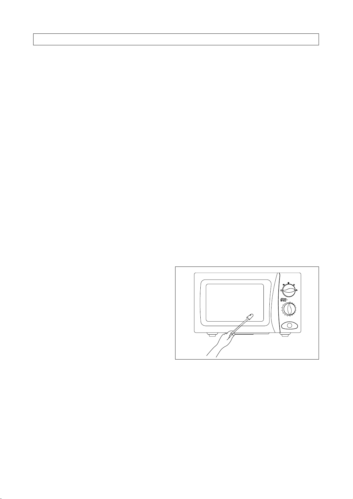
How to set each function
To set MICROWAVE Cooking
• Set the variable POWER SELECTOR to desired power level.
To set GRILL Cooking
• Set the POWER SELECTOR to the (grill) opsition.
To set COMBI Cooking
• Set the POWER SELECTOR to the (combi) opsition.
Set the time control by turning the timer knob and then the oven operate in selected cooking mode.
If turning the timer knob for less than 2 minutes, turn it past 2 minutes and then back to the desired time.
The oven will be turned off automatically when the timer point to “OFF”.
Then take out foods.
• To prevent the oven operating with the door open, your is fitted with safety door interlock switches.
If you wish to inspect the inspect the food during the cooking time, simply open the door.
The oven will sutomatically stop the cooking. To continue cooking, you simply close the door.
• If you wish to stop the cooking during the cooking simply turn the timer knob the point “OFF”.
Cooking can be reset at any time during the cooking cycle by only turing the timer knob.
• Do not let the timer continue to operate after removing food.
NOTE: When using the GRILL or COMBI mode;
• Do not open the door so often, the temperature inside the oven decrease and the cooking may not complete in setting
time.
• Never touch the oven window and metal interior of the oven when taking food in and out, because of the temperature
inside the oven and door is ver high.
• When using thess modes, be careful as the tray will be hot to touch, use oven gloves or pot holders while handing tray.
COOKING UTENSILS
Before use, the user should check the tensils are suitable for use in microwave ovens.
SYMBOL POWER LEVEL OUTPUT POWER
DEFORST 33%
MED-HIGH 77%
HIGH 100%
1
2
3
4
5
6
7
Material Grill cooking Microwave cooking Combined cooking
Glass (general) No Yes (1) No
Glass (heat resistant Yes Yes Yes
Glass-ceramic and ceramic (heat resistant) Yes Yes (1) Yes (1)
Earthenware Yes Yes Yes
China (heat resistant) Yes Yes Yes
Plastic (general) No Yes (2) No
Plastic (heat resistant) Yes (2) Yes (2) Yes (2)
Aluminium foil containers/aluminium foil Yes Yes (3) Yes
Metal baking tins Yes (4) No Yes (4)
Metal (pots. pans, etc) Yes No No
Paper No Yes No
1. Without metal parts or metal trims.
2. Some plastics are heat-proof only to certain temperatres. Check carefully!
3. It is possible to use aluminium foil to shield delicate areas of food (this prevents over-cooking).
4. Metal tins can be used in the comination methods, however if these are very deep, they will greatly reduce the efficiency,
as metal shields the microwave energy from the food.

8
MEASUREMENT OF THE MICROWAVE OUTPUT POWER
Microwave output power can be checked by indirectly measuring the temperature rise of a certain amount of water
exposed to the microwave as directed below.
Procedure
1. Microwave power output measurement is made with the microwave oven supplied at rated voltage and operated
at its maximum microwave power setting with a load of 1,000±5cc of potable water.
2. The water is contained in a cylindrical borosilicate glass vessel having a maximum material thickness of 3 mm
and an outside diameter of approximately 190 mm.
3. The oven and the empty vessel are at ambient temperature prior to the start of the test.
The initial temperature of the water is 10±2˚C(50±3.6˚F).
It is measured immediately before the water is added to the vessel. After addition of the water to the vessel, the
load is immediately placed on the center of the shelf which is in the lowest normal position.
4. Microwave power is switched on.
5. Heating time should be exactly 52 sec.(KOG-36A5) or 47
sec.(KOG-38A5).
Heating time is measured while the microwave generator is
operating at full power.
The filament heat-up time for magnetrons is not included.
6. The initial and final water temperatures are selected so that the
maximum defference between the ambient and final water
temperature is 5K.
7. The microwave power output P in watts is calculated from the following formula:
• ∆T is actual temperature rise.
• t is the heating time.
The power measured should be 800W(KOG-36A5)±10% or 900W(KOG-38A5)±10%.
CAUTION :
1. Water load should be measured exactly to 1 liters.
2. Input power voltage should be exactly 230 volts as specified.
3. Ambient temperature should be 20±2˚C (68±3.6˚F)
P = 4187 X ∆T/t

9
MICROWAVE RADIATION TEST
WARNING
• Make sure to check the microwave leakage before and after repair or adjustment.
• Always, start measuring of an unknown field to assure safety for operating personnel from microwave energy.
• Do not place your hands into any suspected microwave radiation field unless the safe density level is known.
• Care should be takent not to place the eyes in direct line with the source of microwave energy.
• Slowlyapproach the unit under test until the radiometer reads an appreciable microwave leakage from the unit
under the test.
Procedure
A) Prepare Microwave Energy Survey Meter, 600cc glass beaker, glass thermometer 100˚C or 212˚F.
B) Pour 275cc±15cc of tap water initially at 20±5˚C(68±9˚F) in the 600cc beaker with an inside diameter of approx.
9.5cm (3.5 in).
C) Place it at the center of the tray and set it in a cavity.
D) Close the door and operate the oven.
E) Measure the leakage by using microwave energy survery meter with dual ranges, set to 2450 MHz.
- Measured radiation leakage must not exceed the values prescribed below.
• Leakage for a fully assembled oven with door normally closed must be less than 4mW/cm
2
.
- When measuring the leakage, always use the 2 in (5cm) space cone with probe. Hold the probe perpendicular
to the cabinet, door. Place the space cone of the probe on the door, cabinet, door seam, door viewing screen,
the exhaust air vents and the suction air vents.
- Measuring should be in a counter-clockwise direction at a rate of 1 inch/sec. If the leakage of the cabinet door
seam is unkow, move the prove more slowly.
- When measuring near a corner of the door, keep the probe perpendicular to the areas making sure the probe
end at the base of the cone does not get closer than 2 inches from any metal.
If it does, erroneous reading may result.

10
WIRING DIAGRAM
HIGH VOLTAGE
TRANSFORMER
H.V.
CAPACITOR
H.V.
FUSE
H.V. DIODE
CL GM FMTM
POWER SUPPLY :
SINGLE PHASE ~ ONLY
RD
RD WH
FILTER ASS'Y
FUSE
L
NN
GN
L
BR(BK)
BL(WH)
GE(GN)
PRIMARY INTERLOCK
SWITCH(UPPER)
TIMER ASS'Y
TIMER
SWITCHV.P.C
NO
COM
INTERLOCK
MONITOR
SWITCH
NC
BK
WH
BL
SECONDARY
INTERLOCK SWITCH
WH
GY
GY
GY
GY
GY
GY
MAGNETRON
1 3
2
M
RD
NOTE RD : RED
NOTE WH : WHITE
NOTE BK : BLACK
NOTE GN : GREEN
NOTE BR : BROWNNOTE
OR : ORANGE
BL : BLUE
GY : GRAY
GE : GREEN/YELLOW
CL : CAVITY LAMP
FM : FAN(BLOWER) MOTOR
GM : GEARED MOTOR
TM : TIMER MOTOR
V.P.C : VARIABLE POWER CONTROLLER
[CONDITION]
DOOR : CLOSED
TIMER : ON
V.P.C. : HIGH
NOTE :

11
WIRING DIAGRAM(SLOW ACTING RELAY)
HIGH VOLTAGE
TRANSFORMER
H.V.
CAPACITOR
H.V.
FUSE
H.V. DIODE
CL GM FMTM
POWER SUPPLY :
SINGLE PHASE ~ ONLY
RD RD
WH
FILTER ASS'Y
FUSE
L
NN
GN
L
BR(BK)
BL(WH)
GE(GN)
PRIMARY INTERLOCK
SWITCH(UPPER)
TIMER ASS'Y SLOW ACTING
RELAY ASS'Y
TIMER
SWITCHV.P.C
NO
COM
INTERLOCK
MONITOR
SWITCH
NC
BK
WH BL
SECONDARY
INTERLOCK SWITCH
WH
WH
WH
BK
SELECTION
SWITCH 1
SELECTION
SWITCH 2
SELECTION SWITCH ASS'Y
BK BK
GY
GY
GY
BL
HEATER
BL
BR
BR
BR
BL
RD NO
NC
COM
GY GY BL
GY
MAGNETRON
1 3
2
M
RD
RD RD
NOTE RD : RED
NOTE WH : WHITE
NOTE BK : BLACK
NOTE GN : GREEN
NOTE BR : BROWNNOTE
OR : ORANGE
BL : BLUE
GY : GRAY
GE : GREEN/YELLOW
CL : CAVITY LAMP
FM : FAN(BLOWER) MOTOR
GM : GEARED MOTOR
TM : TIMER MOTOR
V.P.C : VARIABLE POWER CONTROLLER
[CONDITION]
DOOR : CLOSED
TIMER : ON
V.P.C. : HIGH
NOTE :

12
CIRCUIT DESCRIPTION
1. When the food is placed in the oven cavity and door is closed.
• The contact of the interlock monitor switch open (NO).
• The contacts of the primary interlock switch and secondary interlock switch close.
2. When the timer is set to the time desired.
• The contact of the timer switch close.
• Oven lamp turn on.
• 230V AC is applied to the high voltage transformer.
• Turntable motor start rotating and glass tray rotating.
• Fan motor rotating and cools the magnetron by blowing air.
• Timer motor operating and point to passing cooking time.
• 3.3 Volts AC is generated from the filamente winding of the high voltage transformer. This filament voltage is
applied to the magnetron to heat the magnetron filament through two noise preventing choke coils.
• A high voltage of 2000 Volts AC is generated in the secondary of high voltae transformer and this secondary
voltage is increased by the action of the diode and the charging of the high voltage capacitor. This resultant
D.C voltage is then applied to the anode of the magnetron. As shown in Fig. 2 the first half cycle of the high
voltage produces in the high voltage transformer secondary charges the high voltage capacitor. Current flow is
in the direction of the dotted-line during the second half cycle, the voltage produced by the transformer
secondary, and the charge of the high voltage capacitor are combined and applied to the magnetron as shown
by the solid line so that oscillations begins.
The disturbance wave generated by the magnetron is prevented by the choke coils of 1.5µH, filter capacitors of
500pF and the magnetron’s shielded case so that TV and radio programs are not impired by noise.
TM
TM CL GM FM
CL GM FM
15A Fuse
Primary
Interlock
Switch Timer
Switch
COM NC
NO
Interlock
Monitor
Switch
Secondary
Interlock
Switch
Timer Motor Cavity Lamp Geared Motor Fan Motor
Fig. 1

13
Fig. 2
3. When the door is opened during cooking.
• Primary interlock switch and secondar interlock switch open to cut off the primary voltage to the high voltage
transformer to stop microwave oscillation.
• Fan motor, timer motor and turntable motor stop rotating.
• Oven lamp turn off.
• As soon as the door is opend, monitor switch close (NC) to create the short circuit.
If the contacts of primary interlock switch and secondary interlock switch are both malfunction, the 15A fuse
blows open due to the large current surge caused by monitor switch activation.

14
PRECAUTIONS FOR DISASSEMBLY AND REPAIR
– Cautions to be observed when trouble shooting.
Unlike many other appliances, the microwave oven is a high-voltage, high-current equipment. It is completely
safety during normal operation. However, carelessness in servicing the oven can result in an electric shock or
possible danger from a short circuit.
You are asked to observe the following precautions carefully.
(1) Always remove the power plug from the outlet before servicing.
(2) Use an insulated screwdriver and ware rubber gloves when servicing the high voltage side.
(3) Discharge the high voltage capacitor before touching any oven components or wiring.
1. Check the earthed.
Do not operate on a two wire extension cord. The
microwave oven is designed to be used with earthed.
It is imperative, therefore, to makes sure it is earthed
properly before begining repair work.
2. Warning about the electric charge in the high voltage
capacitor.
For about 30 seconds after the operation stopped, and
electric charge remains in the high voltage capacitor.
When replacing or checking parts, short between oven
chassis and the negative high terminal of the high
voltage capacitor, by using a properly insulted screw
driver to discharge.
(4) When the 15A fuse is blown out due to the operation of the monitor switch; replace primary, secondary interlock
switch and monitor switch.
Refer to next page for the necessary adjustment.
(5) After repair or replacement of parts, make sure that the screws are properly tightened, and all electrical
connections are tightened.
(6) Do not operate without cabinet.
CAUTION : Service personnel should remove their watches whenever working close to or repairing the
magnetron.
WARNING : When servicing the appliance, need a care of touching or replacing high potential parts because
of electrical shock or exposing microwave. These parts are as follows-H.V. Transformer,
Magnetron, H.V. Capacitor, H.V. Diode.

15
DISASSEMBLY AND ASSEMBLY
1. To remove cabinet.
Remove three screws on cabinet back.
2. To remove door assembly.
1) Remove two screws ¤which secure the stopper
hinge top.
2) Remove the stopper hinge top ¤Ł and door assembly
¤Øfrom top plate of cavity.
3) Remove the stopper hinge top ¤Łfrom door assembly.
4) Reverse the above for reassembly taking care to
replace fixing glue.
3. To remove door parts.
NOTE : After replacing the door preform a check of
correct alignment with the hinge and cavity
front face.

16
(1) Remove the gasket door(A06) from door painting ass’y (A04)
(2) Remove the barrier screen inner(A05) from door painting ass’y(A04).
(3) Remove the hook spring(A08) and the hook(A07).
(4) Remove the hinge stopper top ass’y(A03).
(5) Remove the door frame(A01) from door painting ass’y(A04).
(6) Remove the barrier screen outer(A02).
(7) Reverse the above steps for reassembly.
4. Method to reduce the gap between the door seal and the oven front surface.
(1) To reduce gap located on part ‘A’
1) Loosen two screws on the top hinge stopper,
and then push the door to contact the door seal
to oven front surface.
2) Tighten two screws.
(2) To reduce gap located on part ‘B’.
1) Loosen three three screws on bottom hinge, and then the door to contact the door seal to oven front
surface.
2) Tighten three screws.
(3) To reduce gap locatated on part ‘C’. (See Fig. A)
1) Loosen a screw on the interlock switch assembly located at the bottom of the oven body.
2) Draw the interlock switch assembly inward as possible to engage with hook on the door bottom.
3) Tighten a screw.
(4) To reduce gap located on part ‘D’. (See Fig. B)
1) Loosen a screw on the interlock switch assembly located at the top of the oven body.
2) Follow step (3) 2) and 3).
NOTE: A small gap may be acceptable if the microwave leakage does not exceed 4m W/cm
2
.

17
5. To remove control panel parts.
(1) Remove the screw which secure the control panel
push up two snap fits and draw forward the control
panel assembly.
(2) Remove the screw (B05) which secure the VPC coupler(B04).
(3) Pull out the VPC coupler(B04), VPC knob(B01) and the flat spring (B03) from the control panel(B02).
(4) Remove two screws(B08) which secure the timer ass’y(B07).
(5) Pull out the knob(B09) from the timer ass’y(B07).
(6) Remove the timer ass’y(B07).
(7) Pull out the timer coupler(B06) from the timer ass’y(B07).
(8) Remove the door open button(B12) and button spring(B11) from the control panel(B02).
(9) Remove the door open lever(B10) from the control panel(B02).
(10) Reverse the above steps for Reassembly.

18
6. To remove high voltage capacitor.
(1) Remove a screw ¤which secure the grounding ring
terminal of the H.V. diode ¤Łand the capacitor holder ¤Ø.
(2) Remove the H.V. diode ¤Łfrom the capacitor holder ¤Ø.
(3) Reverse the above steps for reassembly.
High voltage circuit wiring
7. To remove magnetron.
(1) Remove three screws ¤which secure the magnetron
¤Ł.
(2) Remove the magnetron ¤Ł.
(3) Reverse the above steps for reassembly.

19
8. To remove fan motor assembly.
(1) Remove two screws ¤which secure the back cover ¤Łfrom the cavity outer.
(2) Remove two screws ¤Øwhich secure the fan motor ¤Œfrom the back cover ¤Ł.
(3) Pull out the fan ¤ºfrom the motor ¤Œ.
(4) Reverse the above steps for reassembly.
9. To remove transformer.
(1) Remove the four screws ¤holding the H.V.
transformer ¤Ł.
(2) Remove the transformer ¤Ł.
(3) Reverse the above steps for reassembly.
CAUTION : Never install the magnetron without the metallic gasket plate which is packed with each
magnetron to prevent microwave leakage.
Whenever repair work is carried out on magnetron, check the microwave leakage.
It shall not exceed 4mW/cm
2
for a fully assembled oven with door normally cosed.

20
10. To remove insulator Heater assembly.
(1) Remove the four HEX NUTS 1.
(2) Remove the insulator Heater assembly 2.
(3) Reverse the above steps for reassembly.
11. To remove Heater Part.
(1) Remove the HEX NUT 4.
(2) Remove the insulater Heater 1and Heater 2.
(3) Remove the two screws 5.
(4) Reverse the above steps for reassembly.
NO PART NAME PART CODE Q’TY DESCRIPTION REMARK
1 INSULATOR HEATER 3513301100 1 SPP T0.8
2 HEATER 3512801700 1 230V 1000W
3 SCREW MACHINE 7002500613 1 TRS 5X6 MFCR
4 NUT HEX 7392500008 1 6N-2-5 SUS
5 SCREW MACHINE 7002400413 2 TRS 4X4 MFCR
6 SPACER INSULATOR * I 3515000700 2 C3771BD KOG-36A5
7 NUT HEX 7392500011 2 6N-2-5 MFZN
2
1
TOP PLATE
7
6
1
5
2
3
4
Table of contents
Other Daewoo Microwave Oven manuals

Daewoo
Daewoo KOR-637V User manual

Daewoo
Daewoo KOR-6N1G5 User manual

Daewoo
Daewoo KOG-8B5R5S User manual

Daewoo
Daewoo KOG-1M0T User manual

Daewoo
Daewoo KOR-86A77S Assembly Instructions

Daewoo
Daewoo KOR-6L0B User manual

Daewoo
Daewoo KOR-811Q User manual

Daewoo
Daewoo KOR-6NFB User manual

Daewoo
Daewoo KOR-861H User manual

Daewoo
Daewoo KOC-8UOT User manual

Daewoo
Daewoo KOR-81A5 User manual

Daewoo
Daewoo KOG-3885 User manual

Daewoo
Daewoo KOT-1G0S User manual

Daewoo
Daewoo KOG-37250S User manual

Daewoo
Daewoo KOR-1A7G9T(AKM3180S) User manual

Daewoo
Daewoo KOC-1B0K0S User manual

Daewoo
Daewoo 1A0ASL User manual

Daewoo
Daewoo KQG-1N1AS User manual

Daewoo
Daewoo KOR-91RBK-1 User manual

Daewoo
Daewoo KOR-130A User manual