1
C O N T E N T S
1. WARNINGS AND PRECAUTIONS FOR SAFETY --------------------------------------------
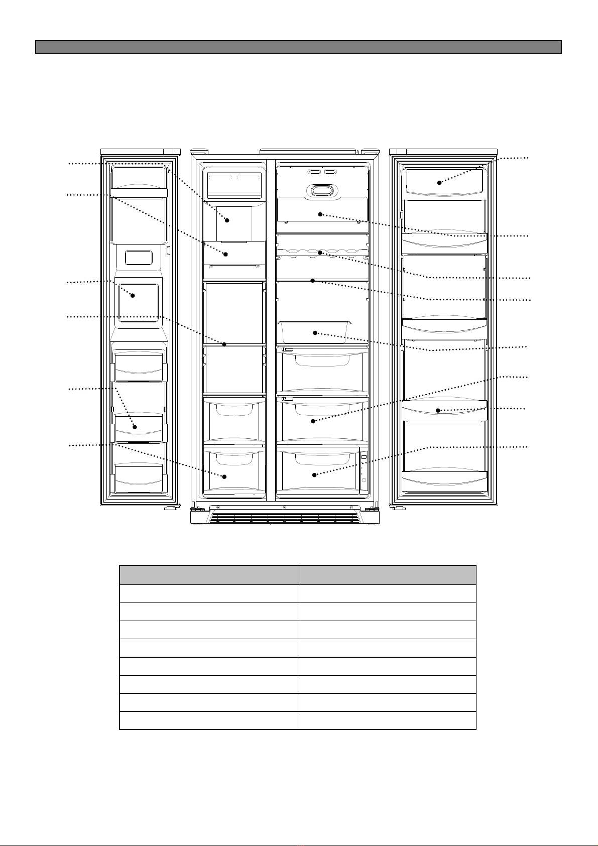
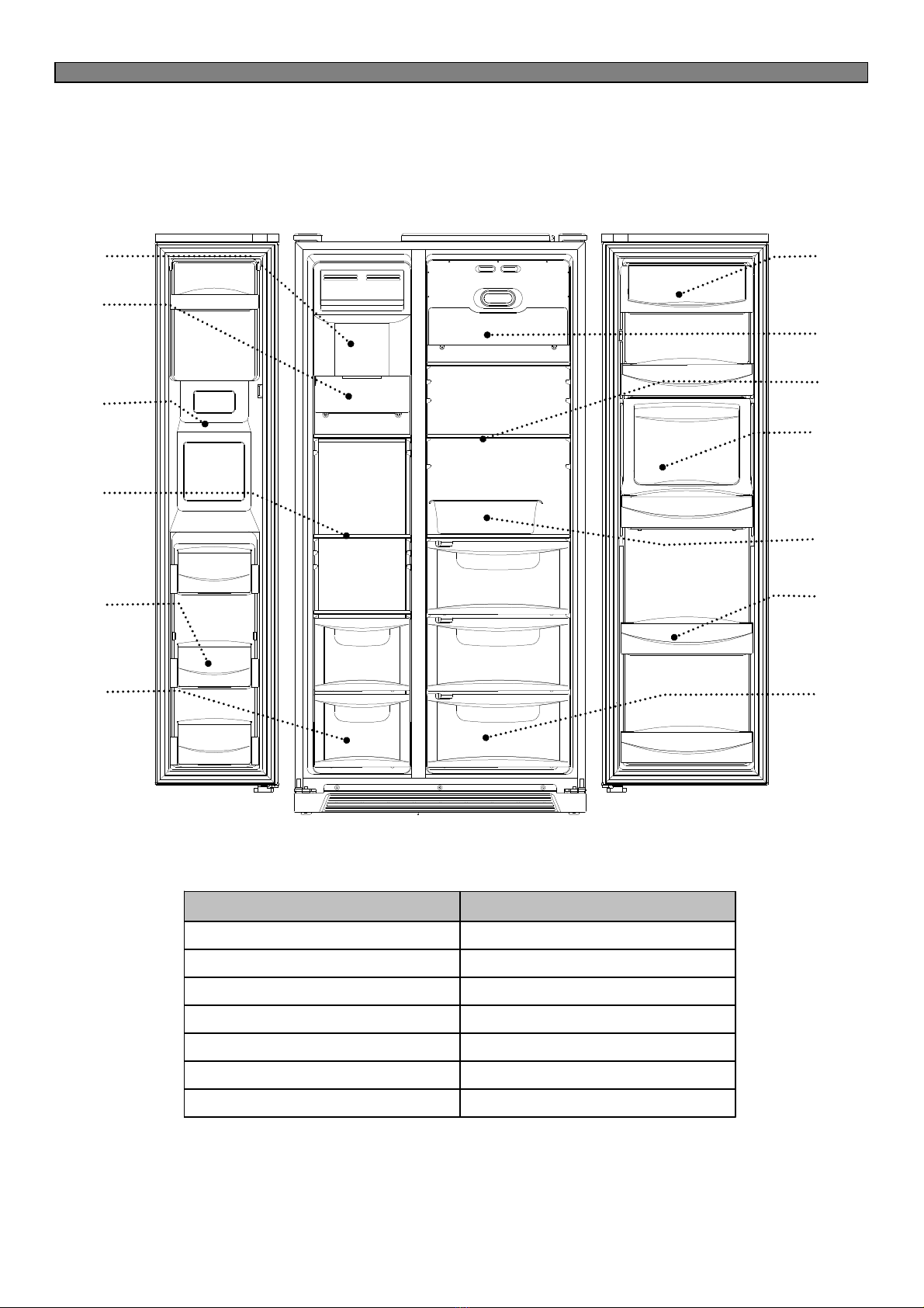
2. EXTERNAN VIEW
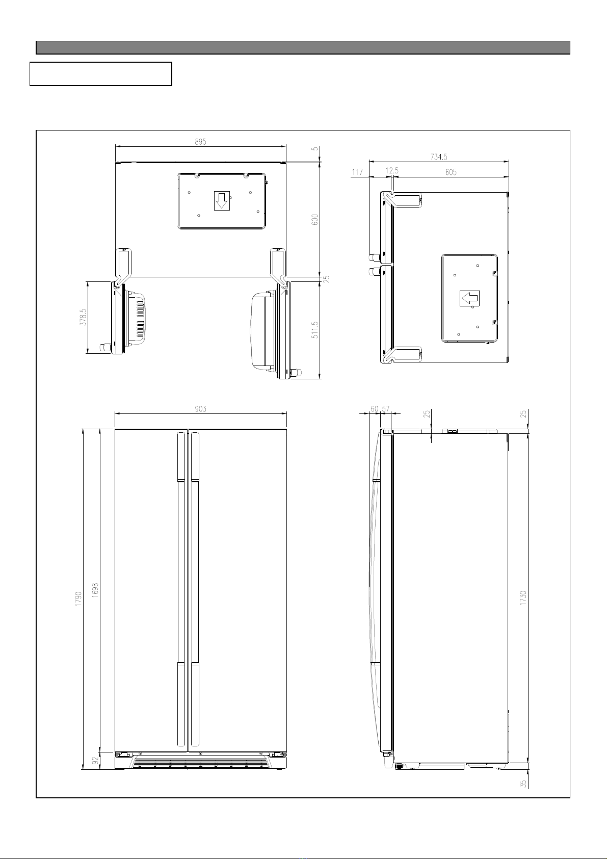
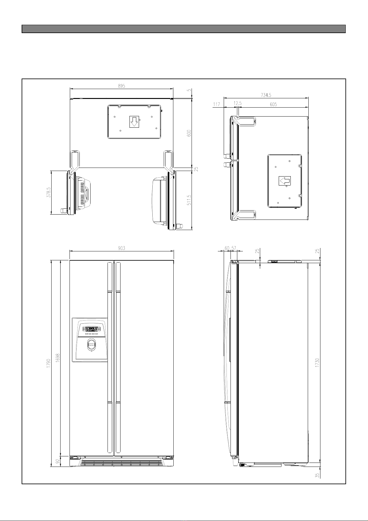
2-1. External Size -----------------------------------------------------------------------------------------
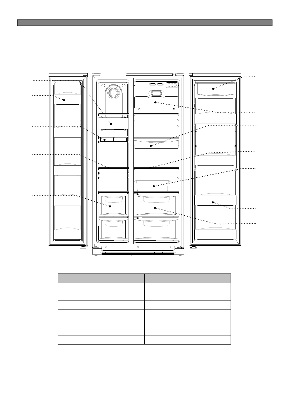
2-2. Name of Each Parts ---------------------------------------------------------------------------------
3. SPECIFICATION ---------------------------------------------------------------------------------------
4. OPERATION AND FUNCTIONS -------------------------------------------------------------------
5. CIRCUIT OPERATION
5-1. Power Circuit Diagram -----------------------------------------------------------------------------
5-2. Function of Each Sensor --------------------------------------------------------------------------
5- . Relay Function ---------------------------------------------------------------------------------------
5-4. Fan Function -----------------------------------------------------------------------------------------
6. DIAGRAM
6-1. Wiring Diagram ---------------------------------------------------------------------------------------
6-2. Circuit Diagram of Main PCB ---------------------------------------------------------------------
7. COMPONENT LOCATE VIEW ---------------------------------------------------------------------
8. HOW TO CHEC EACH PARTS
8-1. Hose Ice Maker Tube -------------------------------------------------------------------------------
8-2. Bracket Geared Motor ------------------------------------------------------------------------------
8- . Dispenser Micro Switch ----------------------------------------------------------------------------
8-4. Dispenser Solenoid Valve -------------------------------------------------------------------------
8-5. Main PCB ----------------------------------------------------------------------------------------------
8-6. Ice Maker ----------------------------------------------------------------------------------------------
9. TROUBLE DIAGNOSIS
9-1. Power Failure -----------------------------------------------------------------------------------------
9-2. Freezer Compartment ------------------------------------------------------------------------------
9- . Refrigerator Compartment -------------------------------------------------------------------------
9-4. Operation Noise of Refrigerator ------------------------------------------------------------------
9-5. Door -----------------------------------------------------------------------------------------------------
10. COOLING CYCLE HEAVY REPAIR
10-1. Summary of Heavy Repair -----------------------------------------------------------------------
10-2. Precaution during Heavy Repair ---------------------------------------------------------------
10- . Practical Work for Heavy Repair ---------------------------------------------------------------
10-4. Standard Regulations for Heavy Repair ------------------------------------------------------
10-5. Brazing Reference Drawing ---------------------------------------------------------------------
11. INSTALLATION GUIDE
11-1. Installation Preparation ---------------------------------------------------------------------------
11-2. If the Refrigerator can not enter the Door ----------------------------------------------------
11- . Refrigerator Leveling & Door Adjustment ----------------------------------------------------
11-4. Water Line Installation ----------------------------------------------------------------------------
11-5. Dispenser Water Flow ----------------------------------------------------------------------------
12. EXPLODED VIEW & PARTS LIST
12-1. FRS(N)-U20IA --------------------------------------------------------------------------------------
12-2. FRS(N)-U20DA -------------------------------------------------------------------------------------
12- . FRS(N)-U20EA -------------------------------------------------------------------------------------
12-4. FRS(N)-U20FA -------------------------------------------------------------------------------------
12-4. FRS(N)-U20GA -------------------------------------------------------------------------------------
2
6
11
14
4
5
7
9
40
42
46
48
49
50
51
52
5
56
57
6
67
74
75
76
77
79
80
81
82
84
85
87
88
98
109
120
1 1