SECTION PVR/DVD Combo REMARK
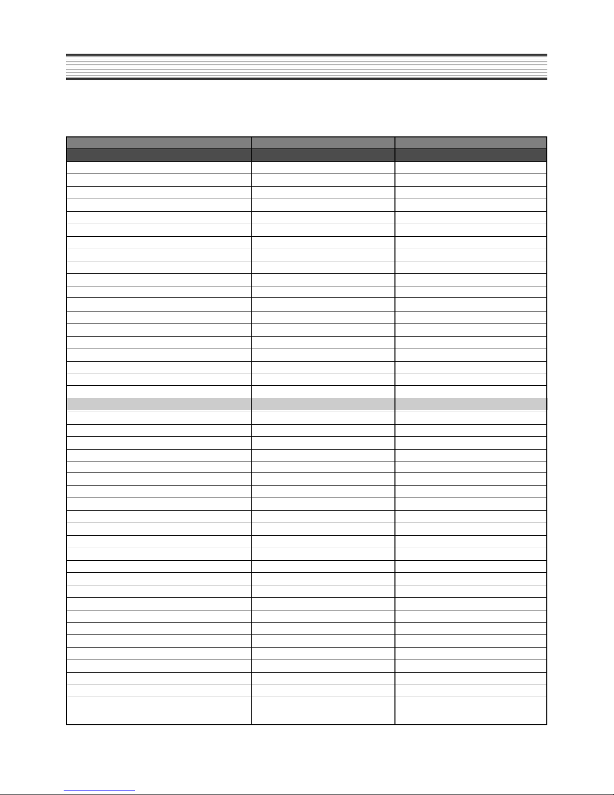
PLAYBACK FEATURES
Skip (FWD / REV) O/O
2x audio during Scan Forward -user selectable O (CD ONLY)
2x Subtitle Display O
Repeat Function (DVD) : Disc / Title / Chapter / A-B O/O/O/O
Repeat Function (CD/VCD) : Disc / Track / A-B O/O/O
Repeat Function (DVD-Audio): Disc / Track / Group O/O/O
Repeat Function (MP3/WMA) : Disc / Track / Dir. O/O/O except WMA
Program Play (DVD/VCD/DVD-Audio/CD//MP3 / WMA) DVD/VCD/CD
Random Play (DVD/VCD/DVD-Audio/CD//MP3 / WMA) CD/MP3
IntroScan ( CD/VCD/SVCD/MP3 ) (No. of Sec.) X/X/X/X
BOOK Mark function (No. of Marks) O
Time Search O
Zoom on Still / Running DVD Video (Zoom x) 1.3x, 2x Zoom (magnify)
Zoom on Still / Running VCD (Zoom x) 2X
Closed caption NTSC (DVD/VCD) X
".jpg" files playback (Thumbnail/Rotation/Slide show) X
".jpg" files playback - other (Zoom/Pan/Fade) X
".jpg" & MP3 or WMA Combination Playback X
Compatibility with Kodak Picture CD X
USER INTERFACE & OPERATION
Graphical User Interface -color selectable X
OSD languages English ,French,German,
Spanish,Dutch,Italian,Swedish,Finnish
On-screen display on/off-user selectable O
Subtitle Selection (DVD) O
Disk Type displayed OSD / Front Panel Display O/O
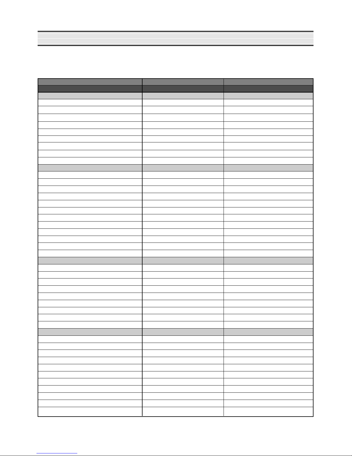
Screen saver On/Off (MP3 / CDDA / Stop / Still / Disc Open)
O
Company LOGO DAEWOO
Resume play O
Black Level adjusment X
Display auto dimming during playback- user selectable X
PBC for VCD 2.0 or SVCD O
Dealer's lock X
Parental lock O
Picture mode selector 4x3, 6x9, letterbox O
Multi-angle playback O
Parental Edit on disks- A-B type deletion of unwanted scenes
X
I
nstant replay- one button push instantly plays back xx frames
X
Upgradeable Flash Memory Capability O
Selectable Audio Streams (total quantity) O
Selectable Subtitle Languages (total quantity) O
Digest O (VCD Only)
Code free Method O
Service Mode Display Method O
6
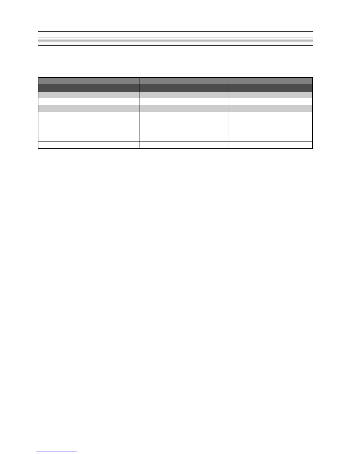
SPECIFICATIONS