AUTO WASHER AUTO WASHER AUTO WASHER AUTO WASHER AUTO WASHER AUTO WASHER AUTO WASHER AUTO
WASHER AUTO WASHER AUTO WASHER AUTO WASHER AUTO WASHER AUTO WASHER AUTO WASHER AUTO WASHER
AUTO WASHER AUTO WASHER AUTO WASHER AUTO WASHER AUTO WASHER AUTO WASHER AUTO WASHER AUTO
WASHER AUTO WASHER AUTO WASHER AUTO WASHER AUTO WASHER AUTO WASHER AUTO WASHER AUTO WASHER
AUTO WASHER AUTO WASHER AUTO WASHER AUTO WASHER AUTO WASHER AUTO WASHER AUTO WASHER AUTO
WASHER AUTO WASHER AUTO WASHER AUTO WASHER AUTO WASHER AUTO WASHER AUTO WASHER AUTO WASHER
AUTO WASHER AUTO WASHER AUTO WASHER AUTO WASHER AUTO WASHER AUTO WASHER AUTO WASHER AUTO
WASHER AUTO WASHER AUTO WASHER AUTO WASHER AUTO WASHER AUTO WASHER AUTO WASHER AUTO WASHER
AUTO WASHER AUTO WASHER AUTO WASHER AUTO WASHER AUTO WASHER AUTO WASHER AUTO WASHER AUTO
WASHING MACHINE
Contents
1. SPECIFICATIONS 2
2. STRUCTURE OF THE WASHING MACHINE 3
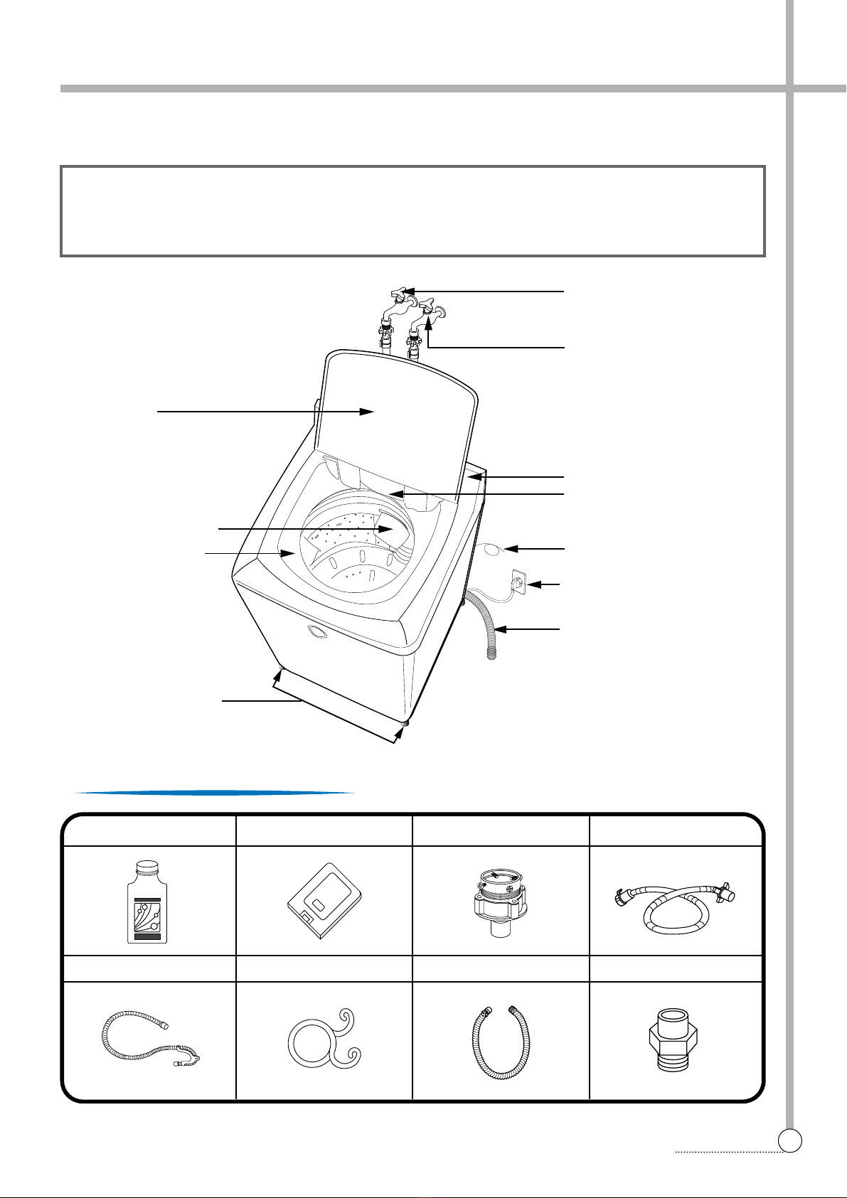
3. DIRECTIONS FOR INSTALLATION AND USE 4
INSTALLATION OF THE UNDER BASE COVER 4
HOW TO INSTALL ON AN INCLINED PLACE 4
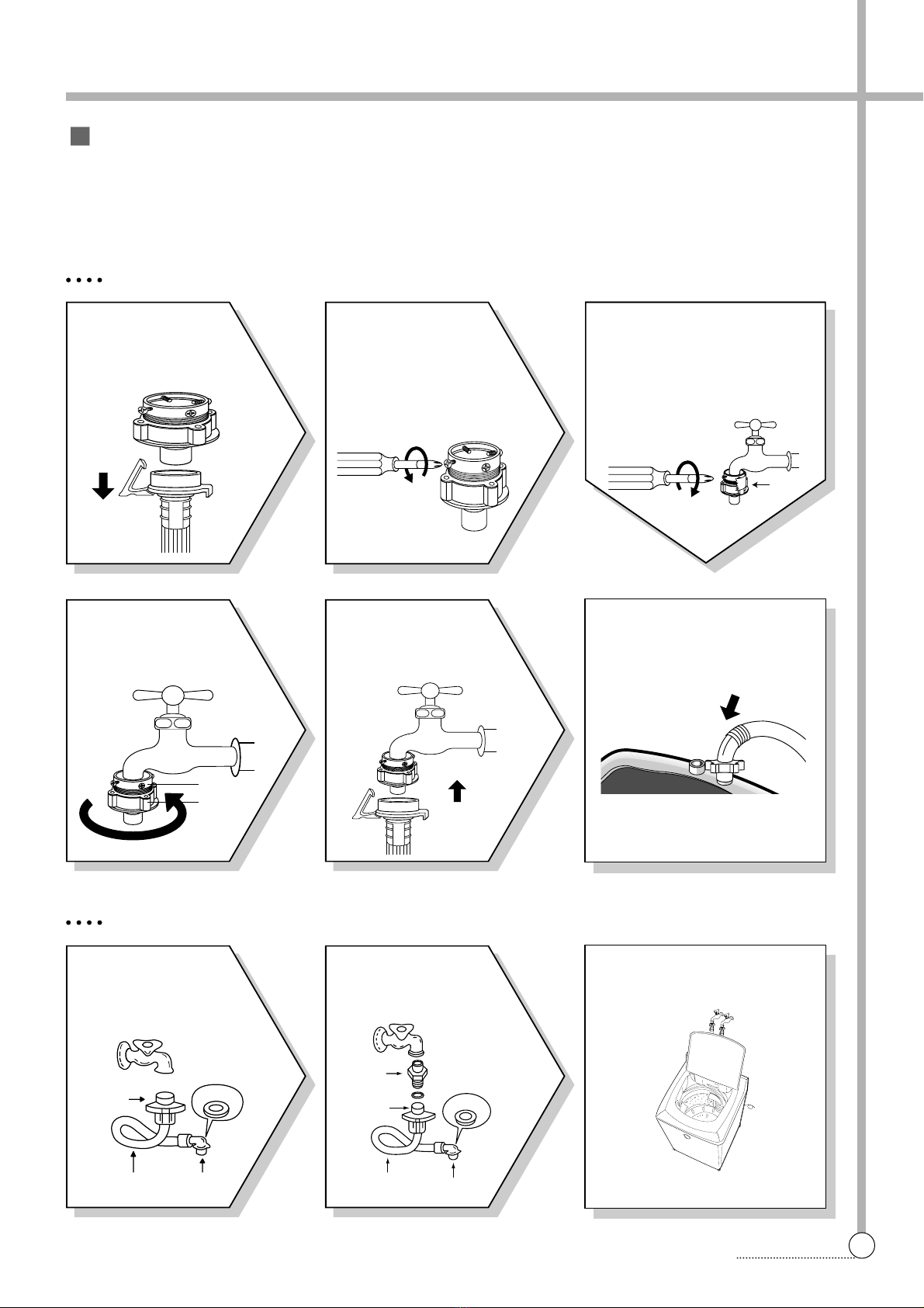
HOW TO CONNECT THE INLET HOSE 5
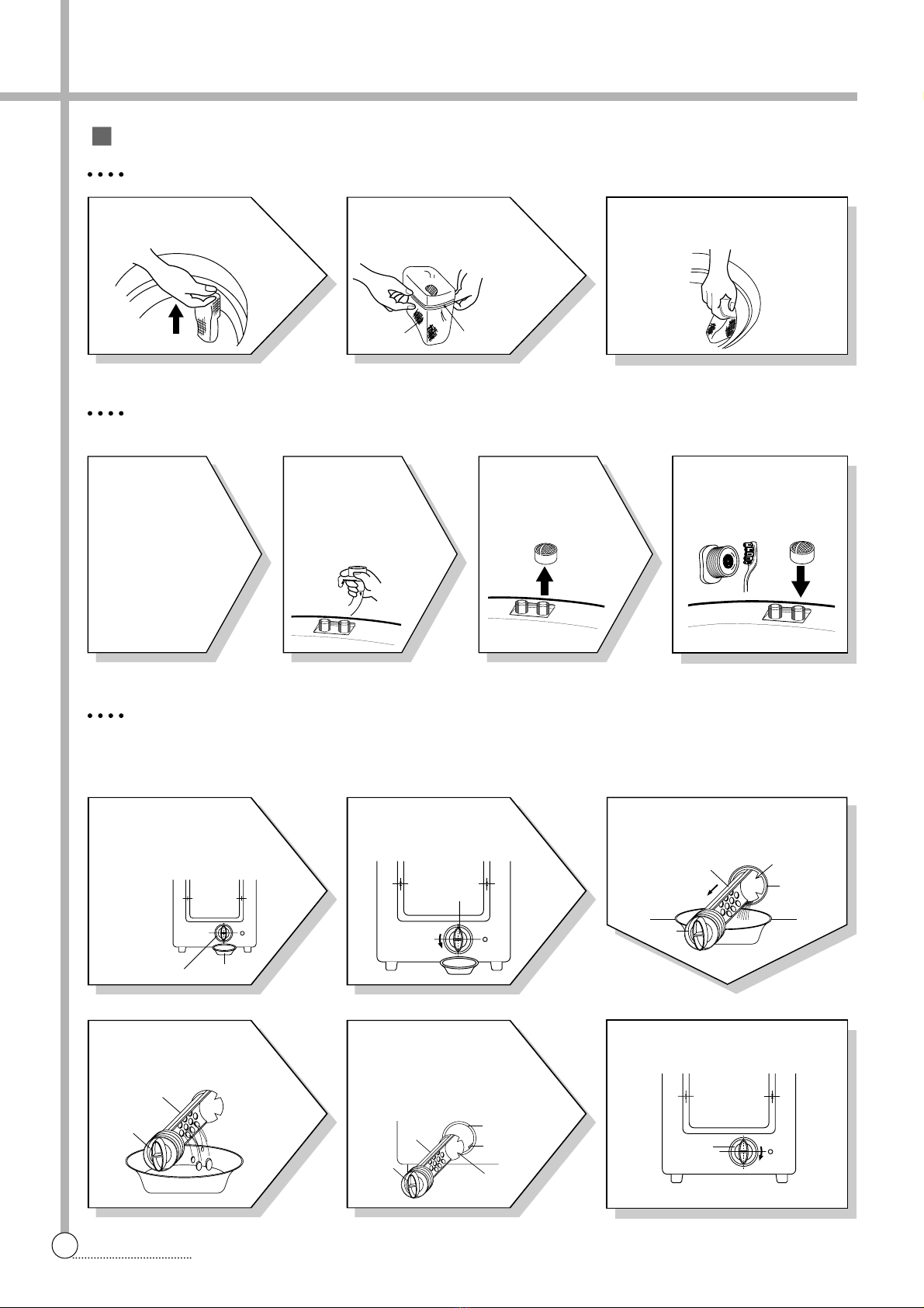
HOW TO CLEAN THE FILTER 6
4. FEATURE AND TECHNICAL EXPLANATION 7
FEATURE OF THE WASHING MACHINE 7
WATER CURRENT TO ADJUST THE UNBALANCED LOAD 7
AUTOMATIC WATER SUPPLY SYSTEM FOR BLANKET WASH 7
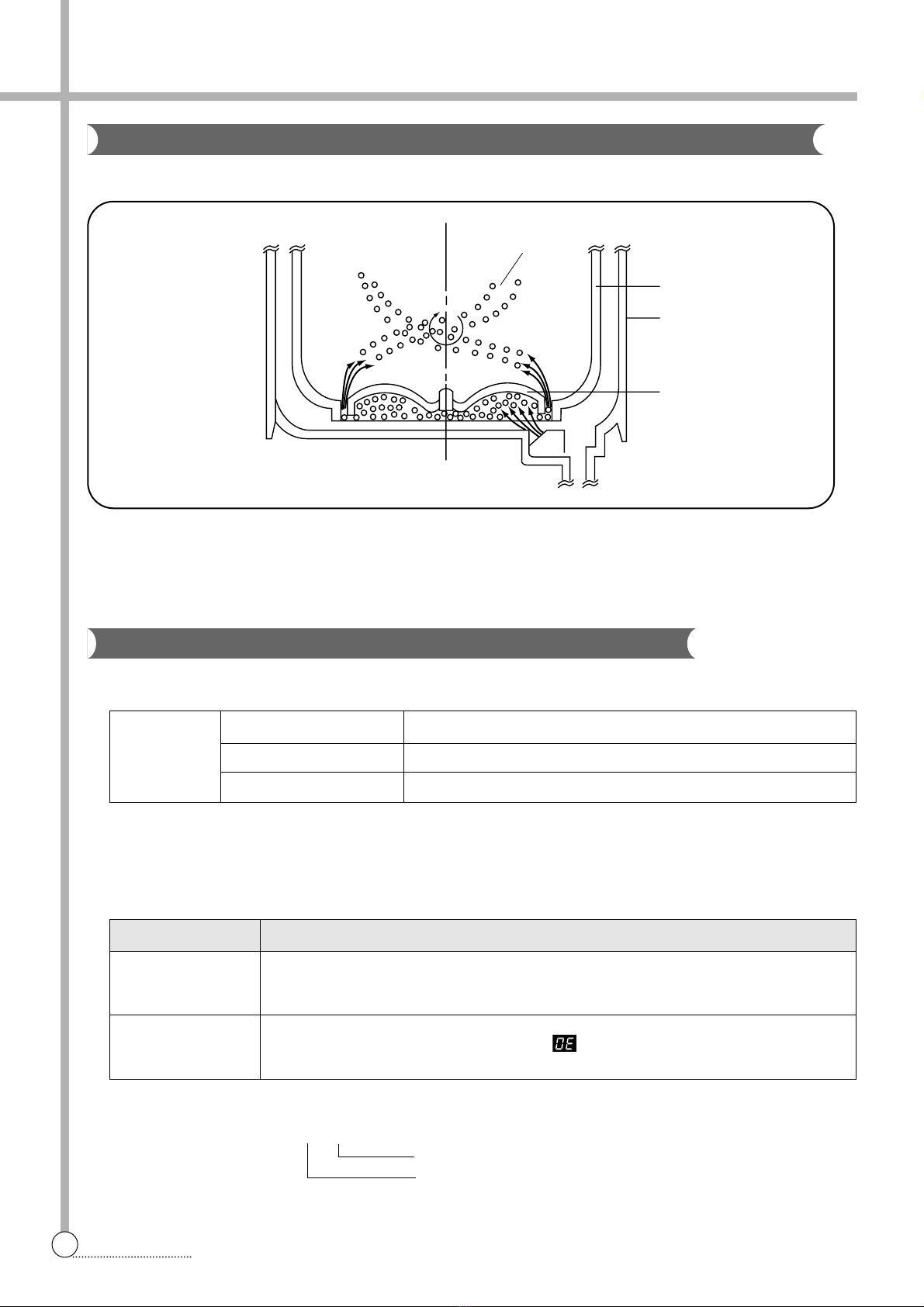
FUNCTION PRINCIPLE OF BUBBLE WASHING MACHINE 8
AUTOMATIC DRAINING TIME ADJUSTMENT 8
AUTOMATIC UNBALANCE ADJUSTMENT 9
CIRCULATING-WATER COURSE AND LINT FILTER 9
LINT FILTER 10
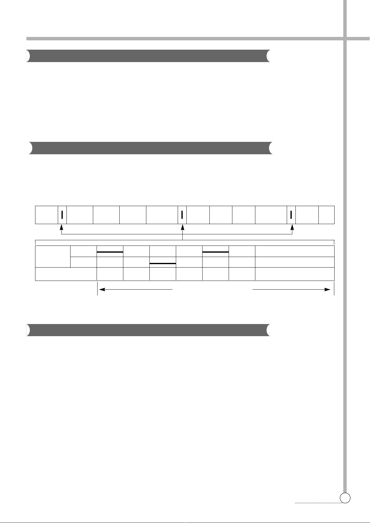
RESIDUAL TIME DISPLAY 10
DRAIN MOTOR 10
GEAR MECHANISM ASS’Y 11
5. DIRECTIONS FOR DISASSEMBLY AND ADJUSTMENT 12
GEAR MECHANISM ASS’Y REPLACEMENT 12
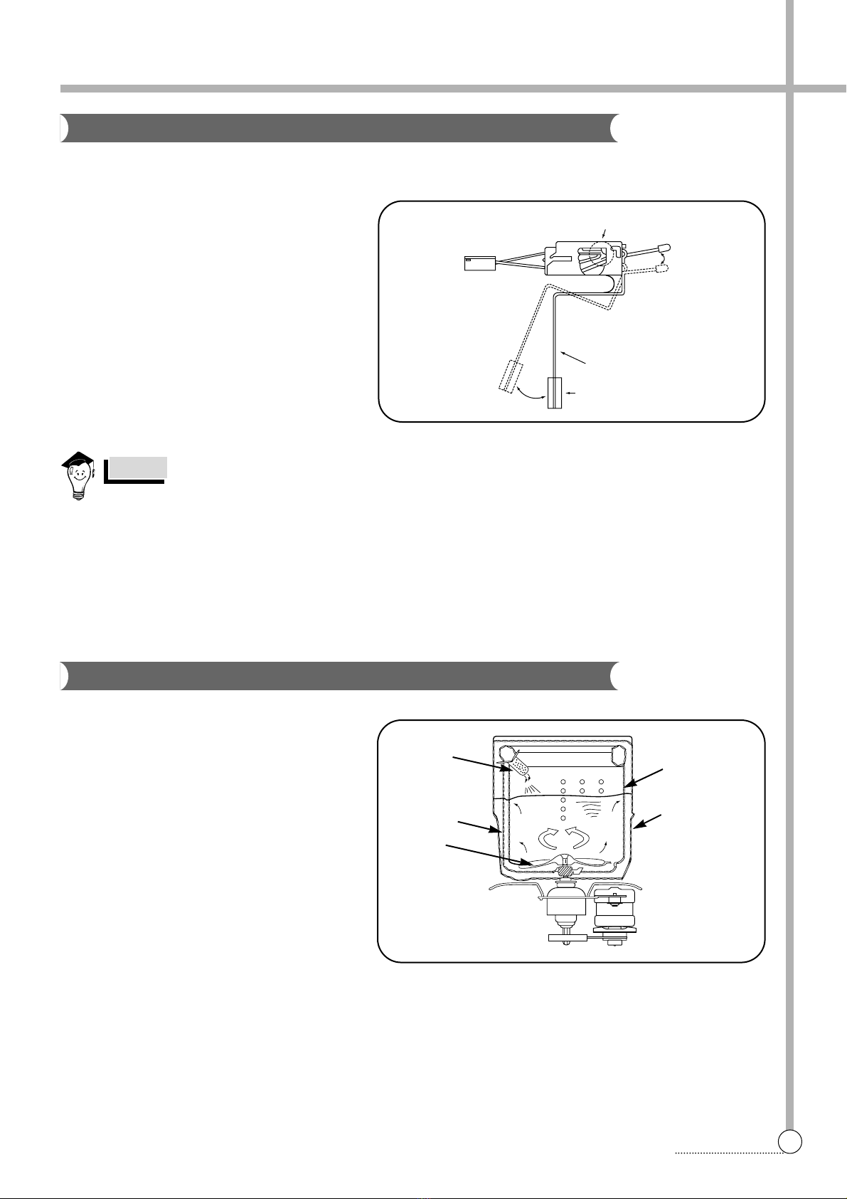
MOTOR SYNCRONOUS AND VALVE REPLACEMENT 14
6. THE REPAIR METHOD OF GEAR MECHANISM FOR CLUTCH
SPRING PROBLEM 15
THE STRUCTURE OF GEAR MECHANISM 15
HOW TO CHECK THE CLUTCH SPRING PROBLEM 16
THE PROCESS OF DISASSEMBLE 17
THE PROCESS OF ASSEMBLE 19
REPLACE THE CASE FILTER ASSY 21
7. TROUBLE SHOOTING GUIDE 22
CONCERNING WATER SUPPLY 22
CONCERNING WASHING 23
CONCERNING DRAINING 24
CONCERNING SPINING 25
CONCERNING OPERATING 26
8. PRESENTATION OF THE P.C.B ASS’Y 27
APPENDIX
WIRING DIAGRAM 28
PARTS DIAGRAM 30
PARTS LIST 34
CIRCUIT DIAGRAM 37