INSTALLATION
Posi on the Camera
BN441E42
Four-channel Network Recording Kit
❼INSTALLATION
Place the NVR
❽
• Ground the unit using the ground connec on of the power
supply to protect the unit from damage, especially in damp
environments.
• Protect the plug and power cord from foot traffi c, being
pinched, and its exit from the unit.
• Do not place the unit in a wet, dusty, extremely hot or an
extremely cold environment; and avoid environments with
strong electromagne c radia on.
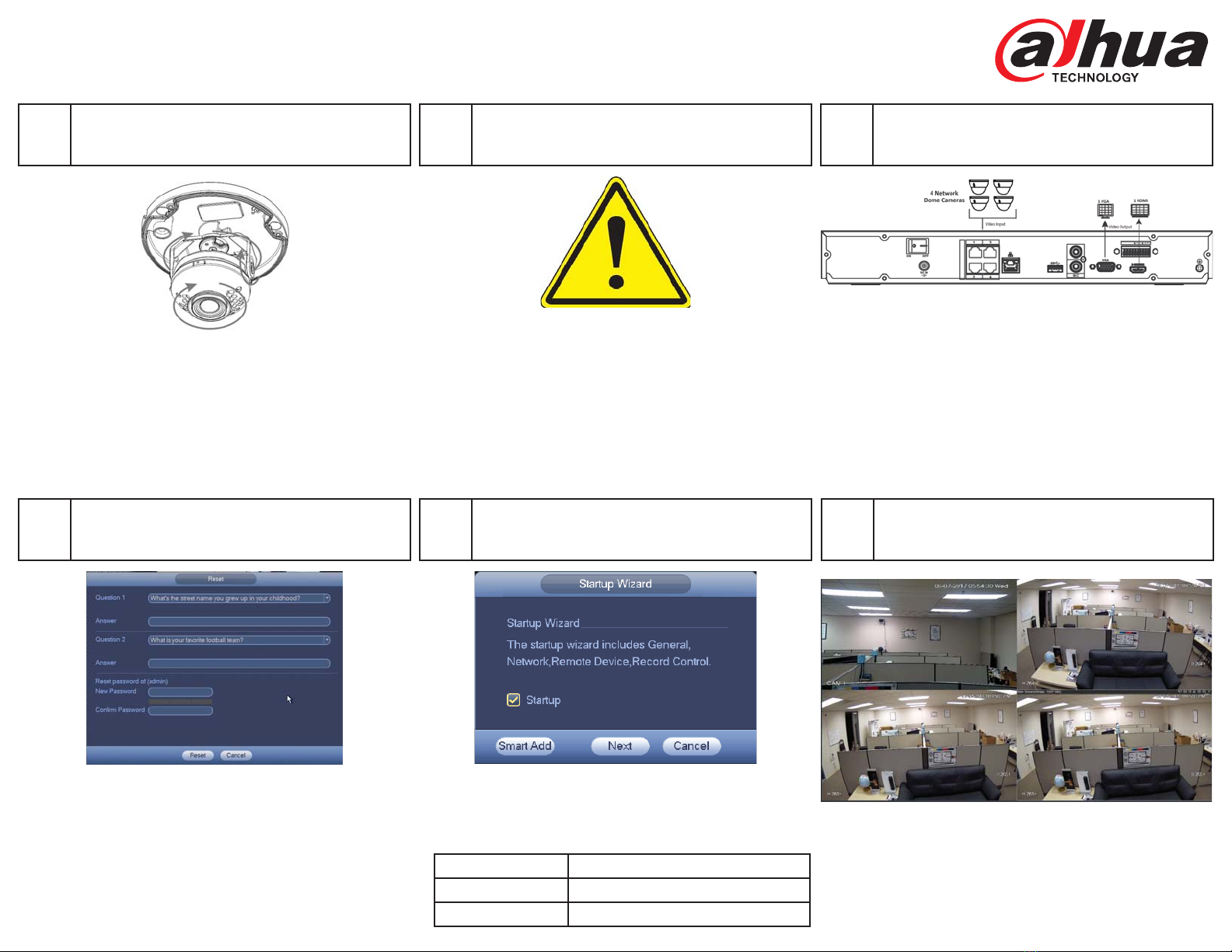
INSTALLATION
Connect Cameras and Peripherals
❾
OPERATION
Log in to the NVR
❿OPERATION
Add Cameras with Smart Add
⓫OPERATION
View Live Video
⓬
Rev. 001.005. Copyright © 2017 Dahua Technology. All rights reserved. Information contained in this document is subject to change without prior notice. Dahua does its best to provide accurate information, but cannot be held responsible for typos or mistakes.
• Connect an Ethernet cable to the RJ45 port for network
access.
• Connect the incoming network cables from the four net-
work cameras.
• Connect a VGA or HDMI cable to the rear panel and to the
display monitor.
• Connect the NVR to the 12 VDC power supply and turn on
the device using the On/Off bu on.
• Loosen, but do not remove the set screws on either side of
the bracket that holds the camera.
• Tilt the camera to adjust the lt angle (0° to +65°). Tighten
the two locking screws on the bracket to lock the lt angle.
• Turn the camera module to adjust image pan orienta on
(0° to +355°).
• Turn the camera base to adjust the rota on of the camera
(0° to +355°).
• Set the Username and Password a er ini al start-up.
• Supply the default password (“admin”) for the Admin
user.
• Supply a new password.
• Supply answers for two confi rma on ques ons in case the
password has to be reset.
• A er Admin Security is set, supply the Username and the
new Password.
• Click Live in the Main Menu.
• Change the Live screen grid if more camera channels are
desired.
• When the network cameras and the NVR are connected to
same router or switch, you can use the Smart Add func on
to add all network cameras to the NVR at the same me
• Default IP Se ngs
IP Address 192.168.1.108
Subnet Mask 255.255.255.0
Gateway 192.168.1.1


