Antique Automobile Radio 283501B User manual

Release Date
January 2014
1955 CHEVROLET WONDERBAR
AM/FM STEREO
Fits 150, 210, BEL AIR & NOMAD
RADIO INSTALLATION
an
OPERATING INSTRUCTIONS
AM/FM9.2
Mo el 283501B
A our Bluetooth® a apter kit option! Answer
incoming calls and place outgoing calls with compatible
phones — all without having to fumble around for your cell
phone You can also stream music from any compatible
phone or tablet — use the dedicated keys to skip or replay
tunes Built in USB 2 1 Amp charger NFC simple pairing
function
ANTIQUE AUTOMOBILE RADIO, INC.
700 TAMPA RD. Palm Harbor, FL 34683 USA (727) 785-8733
For HELP, Questions or Comments email:
support@ra iosforol cars.com

CONGRATULATIONS! You have one of the most unique and sophisticated radios ever built! It is designed for a long trouble free life
and quality sound. Our objective is to preserve the original fit, functions and appearance of your radio while providing superior sound
using the best of the latest digital technology. The more modern features that were not available when your vehicle was new are cleverly
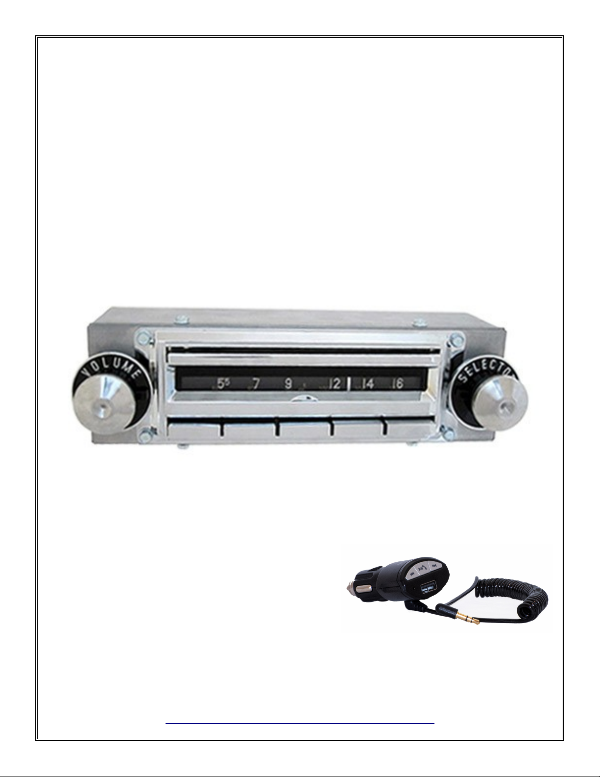
disguised so that they are functional and easily accessible, but are not visible. The face, nobs and pushbuttons are designed and
manufactured to loo and feel just li e the original. The AM dial scale loo s li e the original. The FM dial scale is in the bac ground.
Please ta e a few minutes to read this manual and familiarize yourself with all of the features of this radio. Note: The dial pointer and
pushbuttons are electrically operated and will not unction without power. Although this radio is considerably smaller than the original, it
will fit in the dash without any alterations. The radio is designed to wor well with the original antenna. Do not use the original
speakers. They will not handle the power or the frequency range of this radio.
Be ore you begin installation: Be Safe! Disconnect one battery terminal and leave it disconnected until installation is complete. Ma e
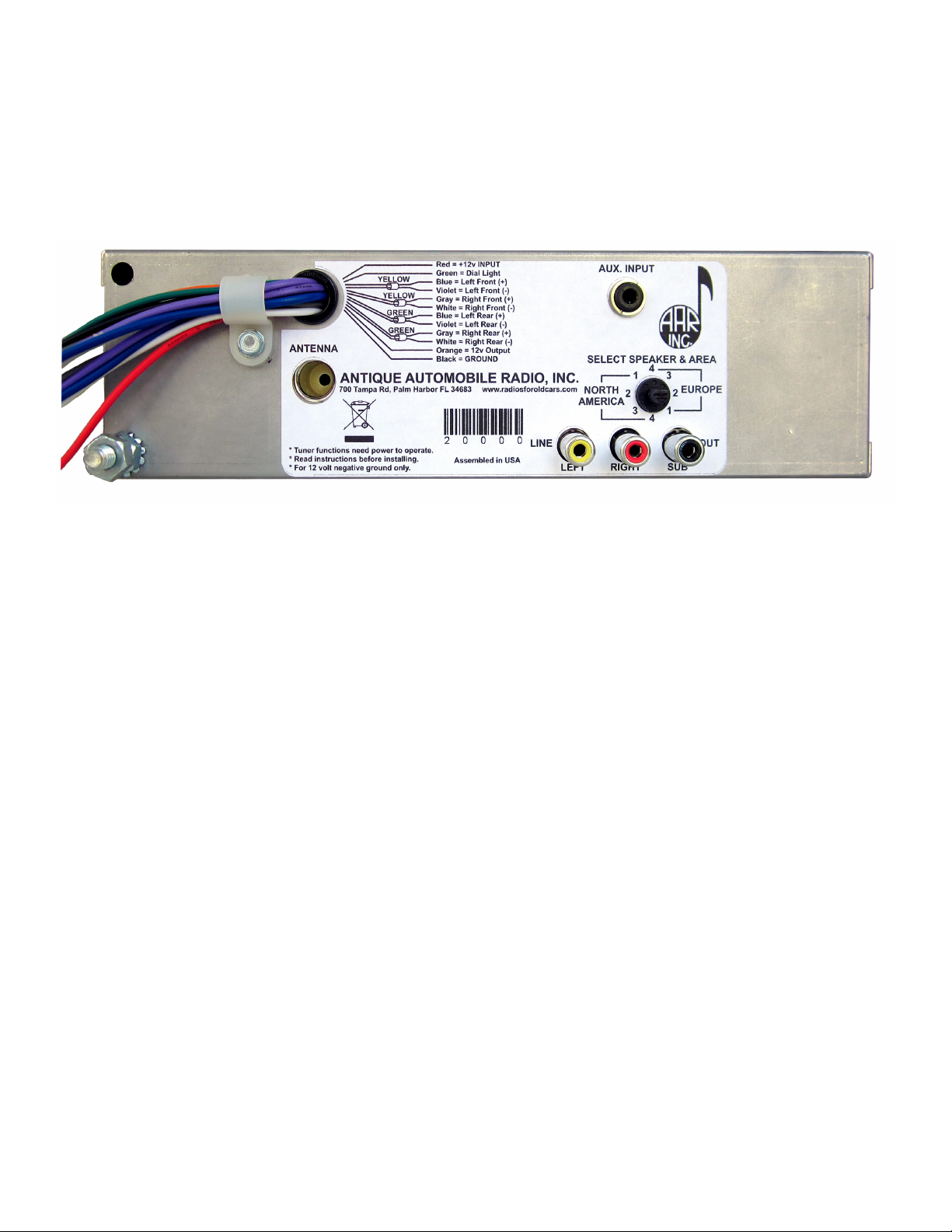
sure you are familiar with the options and features programmed into this radio. Locate the antenna jac , the auxiliary input, line outputs
and other options you may need before you mount the radio. If you want to “bench test” the radio use a fully charged battery. DO NOT
operate this radio directly from a battery charger. Serious damage may result!
Be sure your radio voltage and polarity matches your vehicle. This radio is built for 12 volt negative ground systems only! The radio has
several protection circuits to help prevent serious damage from wiring errors and power faults in the vehicle electrical system. Never use a
fuse rated for more than 10 Amps!
A major consideration will be spea ers. There are many possibilities for additional spea er placements. You will have to decide what will
wor best for your application. Will it matter if the spea ers show? You might consider ic panel, door spea ers, or mounting spea ers
under the dash where they’re out of sight. You can add an external amp or sub woofer (see next page).
Use one 4 ohm spea er for each channel you want to connect. Ma e sure it can handle the wattage! Unless you cran it all the way up
regularly, 30 or 40 watt RMS ratings should be sufficient. The higher the SPL rating of the spea er, the better it sounds. Loo for an SPL
of 88 or better. A good full range spea er should have a frequency range from less than 40 Hz to better than 20 Hz.
Pay attention to polarity! Spea er terminals will be mar ed with a + and - , or a red dot on the + terminal. If all spea ers are connected to
the proper polarity, they will operate in harmony. If they are not properly phased, you will not hear the full fidelity of the radio. Note: -
does not mean ground! This is a high power radio in which both spea er lines are driven with high currents! Never allow any spea er lead
to become grounded when the radio is on!
Operating Your Radio
Band selection: The radio will always start with the last band and station you were listening to when power was turned off. To change
bands, turn the radio off, then on again quic ly. If the radio has been off more than 5 seconds, it will start with the last band selected.
Tuning: Your radio has an AM dial made to loo li e the original. In the bac ground there is also an FM dial scale. Both are illuminated
at night. There is a small LED in the bac ground that will be red when the radio is set to the AM band, green when the radio is set to the
FM band, and yellow when the receiver loc s on to a stereo signal. Turning the tuning nob will move the dial pointer up or down the dial
scale. The radio can also be tuned using presets (see Setting pushbuttons) or with the Wonderbar. Pressing the bar above the dial will
move the pointer up the dial to the next station. Note: the dial pointer will only move when the radio is turned on.
Tone: The tone control (behind the volume control) provides flat bass and treble near the center position. Turning the control cloc wise
boosts bass, and counter-cloc wise boosts treble.
Balance: Your radio has a balance control behind the tuning control. Turning the balance nob will shift the audio between the left
spea er(s) and the right spea er(s). In a stereo system, the audio information sent to the right channel is often different than the left
channel. When you set the balance to the extreme left or right, the radio will automatically switch out of the stereo mode and all of the
information for both channels will be present in the spea er that is selected (Mono mode).
Fader: In order to allow adjusting the front/rear spea ers without adding visible controls, your radio has a software control that is shared
with the balance control. To access the fader, tune to an FM station and set the balance control for the best sound. After you’ve listened for
a few seconds, tune rapidly to the top of the dial. The LED in the dial bac ground will begin to flash. After a few seconds, the last station
you were listening to will start playing again. Use the balance control to adjust the front/rear fader. When you tune away from the top of
the dial, the radio will resume normal operation, and the balance control will no longer affect the fader function. The fader settings are
permanently stored (until you change them). Every time you turn on the radio, the fader values you last set will be re-loaded. Note: The
ader is only operational in the 4 speaker setting.
Setting pushbuttons: Your radio has 5 presets for FM, and 5 presets for AM. A major difference between the original radio and this one
is the way the pushbuttons are set. Never pull out or attempt to turn the buttons! When you push a button, the radio will start playing the
selected station, and the dial pointer will move to the selected location. To set a button to a different station: (1) Tune in the desired
station. (2) Press and hold the button you want to set. The tuner will move to the previous setting. (3) After about 2 seconds, the radio will
begin playing the newly selected station. The dial pointer may cycle a few times to locate the correct position. This is a normal procedure.
The dial pointer will stop at the new station. (4) Release the button. Be aware it ta es a couple of seconds to write the new pushbutton
data to permanent memory. You can continue to set other buttons or tune other stations, but if the radio is turned off before the write cycle
is completed, the new stations may not be saved.
Speci ications
11-16 Volts DC Negative ground only
Output: 180 W. RMS (45 W x 4 spea ers @ 4Ω 14.4 V, 1 Hz)
10 Presets (5 AM, 5 FM) Digitally tuned w/analog display
Dimensions: 8.75” W x 2.55” H x 3” D (behind dash)
3.5mm stereo input jac , Standard (Motorola) antenna jac
Left, right and sub woofer outputs use standard RCA jac s
1/2” shafts on controls are identical to original
Memory retention (presets and user settings) more than 40 years
(1)

Your radio has a 12 pin connector for the speakers, power, and options. See inset below for more details. There is one red (fused) wire.
This is the main power input. It should be connected to the 12 volt ccessory circuit. There is a green wire that is used for the dial
light. It should be wired to the dash light circuit ahead of the dimmer rheostat so that the radio lights come on when the other gauge
lights are turned on. The wiring for the front speakers includes a blue(+) and violet(-) pair for the left front speaker, and a gray(+) and
white(-) pair for the right front speaker. Each front pair will have a yellow band around it. The rear speaker wiring also has a blue(+)
and violet(-) pair for the left rear speaker and a gray(+) and white(-) pair for the right rear speaker. Each rear pair will have a green
band around it. Your system may not use all of the speaker connections. Be careful to tape up any unused wires where they can not
touch anything. The orange wire is a switched 12 volt output used to provide power for options like remote turn-on for power
amplifiers, power antennas, etc. Do not use it to power loads greater than 4 amps. The black wire is the system ground. This wire
should be connected to a solid chassis ground.
The ANTENNA jack is located beneath the wiring harness exit. It will accept your original antenna plug.
The AUX. NPUT jack in the upper right is a standard 3.5 mm stereo jack. It is provided to allow accessories like MP3 players to be
added to your system. Our Bluetooth® adapter kit option includes a panel mount extension cable that allows you to move this jack
to a more accessible position. To switch to the auxiliary input mode, tune the radio to the extreme low end of the dial in either band.
(Hint:Set a pushbutton at this point to allow rapid switching). The radio will resume playing when you tune towards the middle of the
dial. The volume, tone, and balance controls will be functional in the UX mode, but the alternate fader control will not be accessible.
If the accessory is powered by the orange wire, when the radio is turned off, the accessory will automatically turn off. You should
adjust the accessory audio level to match the level of the radio. Check the instruction manual for your specific option for how to set the
audio level.
Below the ux. input there is an 8 position switch that allows you to select certain options. You can customize your radio for 1, 2, 3, or
4 speakers, and choose reception for merican or European broadcast frequencies. The M broadcast band in the mericas is 530 to
1710 kHz in 10 kHz steps, and for all of Europe, the UK and Japan it is 531 to 1629 kHz in 9 kHz steps. The FM broadcast band in the
mericas is 87.5 to 107.9 MHz in 200 kHz steps, and for western Europe and the UK it is 87.5 to 108.0 MHz in 100 kHz steps. Japan
and eastern Europe FM frequencies are not compatible with this receiver. Your radio is shipped with 4 speakers and North merica
selected. The switch has an arrow and a screwdriver slot molded into it. It is intended to be set (if necessary) before installation. It is
only read when the radio is powered on. ny further changes will be ignored until the next time the radio is powered on. In the 4
speaker position all 4 speakers are active and the balance and fader controls work as described. In the 3 speaker position, the left front
speaker is turned off, the right front speaker is always on. The balance control shifts between the left rear and right rear speakers and
there is no fader. In the 2 speaker position both rear speakers are turned off, the balance control is active but there is no fader. In the 1
speaker position, only the right front speaker is functional and neither the balance or fader controls have any effect. In this setting the
receiver and the aux inputs operate in mono mode so that the information from both the right and left channels will be heard in the
single speaker. The stereo indicator will not function.
Below the speaker switch are 3 color-coded RC jacks. These are line outputs for an external power amplifier. The Left (white) and
Right (red) jacks are stereo line outs, and the black one is for a sub-woofer amp input. While a discussion of external amplifiers and
their myriad of options is beyond the scope of this manual, we have had excellent results testing this radio with a JBL model GTO-
3EZ power amplifier. It is ready to plug in and play right out of the box, the instructions are clear and easy to follow, and it sounds
great! While we do not sell or endorse any particular amplifier or brand, we found this one to be readily available on line and well
suited to our requirements in the testing department.
There is a ¼ 20 stud on the back of your radio with a 7/16” nut. In the box that your radio came in is a 9” backstrap that can be easily
shaped to support your radio. It will provide a better ground and help support the radio while taking some of the stress off of the
control shafts. It should be bolted to the steel dash brace below the radio (see next page).
The Bluetooth® word mark and logos are registered trademarks owned by Bluetooth SIG, Inc. and any use of such marks by ntique
utomobile Radio, Inc. is under license. Other trademarks and trade names are those of their respective owners.
(2)

NOTES ON INSTALLATION
If you intend to use our Bluetooth® adapter kit install the extension cable provided with the kit. Refer to the Bluetooth®
instructions
The front of your new radio is a dimensionally exact copy of the original, so it will install the same way that the original radio
did. The radio is much smaller when viewed from the back than the original was, so the original mounting bracket won t fit.
Included with your radio is a 9 inch backstrap that can be easily cut and bent to any shape or size. It should be attached to the
threaded ¼ -20 stud on the back of the radio near the antenna jack and to the Plenum Chamber Bracket directly behind the
radio. Pull the outer knobs from the control shafts. Remove the backrings and the outer shaft nuts. Remove the control shaft
escutcheons. Do not remove or loosen the inner shaft nuts! Position the radio in the dash, replace the control shaft escutcheons
over the control shafts and secure in place with the shaft nuts. Do not over-tighten! Replace the backrings and outer knobs.
DIAGNOSTICS
No Sound: Check for a good fuse with proper rating. When the radio is turned on, the orange wire should have 12 volts present.
Radio will mute when no station is received. Make sure antenna is plugged into the proper jack. If an option is plugged in, make
sure it’s not on. Before installation make sure the switch on the back of the radio is set for the correct speaker option and
country.
Weak or No Reception: Check continuity between the center pin of the antenna plug and the antenna mast. It should read 0
ohms (like a short) Next, check continuity between the center pin of the antenna plug and the car body. It should not read (like
an open circuit). If you’re in a metal building, reception may be limited. Try it outside.
I nition Noise: Usually caused by an ungrounded antenna shield. The base of the antenna must make good contact with the car
body. This problem often shows up after a good paint job! Make sure the engine grounding straps are in place, clean and tightly
bonded to the frame.
Distortion: Check to see if your speakers can handle at least 45 watts RMS. Small speakers that can only reproduce high
frequency will distort on bass notes. Make sure speakers are properly installed. Make sure that no speaker is grounded. Every
speaker lead should measure about 6 volts to ground with the radio on and volume low. Resistance in the DC power input
wiring can cause the amplifiers to “starve”. If distortion seems to increase with volume, measure the voltage on the orange wire.
If the voltage drops when the volume is raised, it is an indication of resistance between the battery and the radio – usually at the
fuse block, but sometimes in the ignition switch. If the backstrap is not bolted to a clean metal ground, try running a heavy
ground wire from the ground lug on the radio directly to the firewall.
Radio shuts off after a few minutes: The radio has thermal protection built in to prevent damage from excessive heat. Possible
causes are shorted or grounded speaker wires. See if any unused wires can touch anything. Make sure the heater or defroster
duct isn’t blowing directly on the radio.
Dial pointer issues: If power is interrupted while the dial pointer is moving or saving its position, the dial pointer may get
“lost” or become misaligned. If this happens, turn the tuning knob to either end. The dial pointer will reset itself.
3 (end)
Table of contents