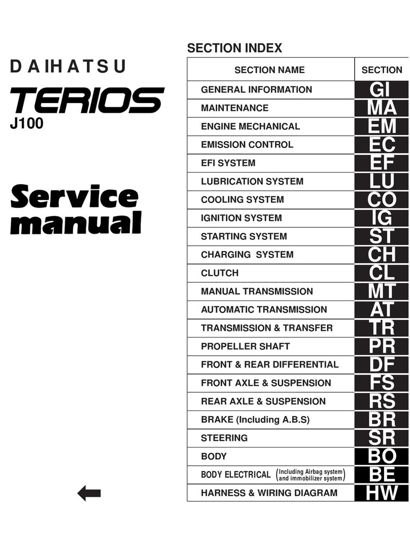
Daihatsu TERIOS J100 Guide

MAINTENANCE
MAINTENANCE REQUIREMENTS ... MA– 2
MAINTENANCE SCHEDULE ............ MA– 3
SCHEDULE FOR SEVERE
DRIVING ..................................... MA– 5
MAINTENANCE OPERATION ........... MA– 6
ENGINE ............................................. MA– 6
COLD ENGINE OPERATION ........ MA– 6
HOT ENGINE OPERATION .......... MA–13
CHASSIS ........................................... MA–26
BRAKE FLUID .............................. MA–26
BRAKE PEDAL ............................. MA–27
PARKING BRAKE HANDLE .......... MA–27
BRAKE HOSE & TUBE ................. MA–28
FRONT BRAKE ............................. MA–29
REAR BRAKE ............................... MA–32
BRAKE BOOSTER HOSE ............. MA–34
BRAKE MASTER CYLINDER ........ MA–35
MUFFLER AND EXHAUST PIPE ... MA–37
AUTOMATIC TRANSMISSION ..... MA–37
CLUTCH ....................................... MA–38
MANUAL TRANSMISSION,
TRANSFER, FRONT AND REAR
DIFFERENTIAL ........................... MA–39
PROPELLER SHAFT ..................... MA–40
DRIVE SHAFT ............................... MA–40
WHEEL HUB NUT ........................ MA–40
WHEEL BEARING ........................ MA–40
STEERING SYSTEM ..................... MA–41
WHEEL ALIGNMENT .................... MA–42
SHOCK ABSORBER ..................... MA–43
SUSPENSION ARM, CONTROL
ARM & DUST COVER ................. MA–43
DAIHATSU
MA
JMA00001-00000
NO. 9710-JE
J100
TO INDEX

MAINTENANCE REQUIREMENTS
The scheduled maintenance service is important to ensure trouble-free, safe and economical driving.
Failure to perform the scheduled maintenance may cause an accident or serious damage.
If you conduct the periodical maintenance, Daihatsu car owners may reduce the chance of accidents or
car problems. Furthermore, it becomes possible for you to find at an earlier stage malfunctions which may
lead to serious damages. Consequently, potential vehicle damage can be prevented or the degree of the
damage can be minimized.
Therefore, all of the persons who are concerned with servicing the Daihatsu vehicles should offer the peri-
odical maintenance service to Daihatsu car owners in order that they may be protected from accidents or
unexpected problems.
To prevent malfunctions in advance, however, conducting the periodical maintenance service only is insuffi-
cient. It is essential that owners themselves perform maintenance, such as the pre-starting check de-
scribed in the owner’s manual, so that the vehicle exhibits no abnormal change or phenomenon. Hence,
please explain to owners about the necessity of maintenance performed by them. However, malfunction
may occur on those vehicles which are always checked by their owners. For instance, if a part instructed to
be replaced periodically should be used beyond the replacement intervals and the life of the part has ex-
pired, there are cases where malfunction occurs suddenly despite the fact that no malfunction has taken
place until yesterday. To prevent such malfunction in advance, be sure to replace parts recommended to
be replaced periodically at the specified replacement intervals.
This section describes those items of the scheduled maintenance service recommended by the Daihatsu
and their intervals. Be sure to observe the maintenance schedule.
MA–2
JMA00002-00000

MAINTENANCE SCHEDULE
NOTE:
•Perform the periodical maintenance at the specified mileage or the time whichever comes first, un-
less otherwise specified.
•Continue to perform the periodical maintenance after 100,000 km (60,000 miles) at the same inter-
vals as before 100,000 km.
•If the vehicle should be operated under severe driving conditions, operated occasionally, operated in
dusty areas, repeating short trip, operated under extremely cold climate and/or on salted roads, it is
necessary to perform some maintenance items more frequently than the regular maintenance sched-
ule.
•This maintenance schedule prepared based on requirements mentioned in the owner’s manual
which are to be performed by the Daihatsu owner thoroughly.
MA–3
Section Item What to do Inspection interval See
page
×1000 km 1 10 20 30 40 50 60 70 80 90 100
0.66 121824303642485460
— 0.5 1 1.5 2 2.5 3 3.5 4 4.5 5
×1000 miles
Years
Cleaning
Check
•Damage
Engine
Exhaust
emission
control
system
Air cleaner element
Valve clearance Check & adjustment
MA–6
MA–18
Engine oil & oil filter Change (Use API: SG or higher grade) MA–13Every 12,000 km
Every 100,000 km
Every 40,000 km
Every two years
Every 100,000 km
Every eight years
Fuel filter Change MA–9
Coolant (Long-life coolant) Change MA–23
Ignition timing Check & adjustment MA–21
Charcoal canister Check
•Function
•Damage MA–11
Evaporative emission hoses Change MA–12
Exhaust pipe & muffler
mounting
* Replace every 10,000 km when API SF grade oil is used.
Check
•Tightness
•Damage MA–37
Blow-by gas recirculation
hose (Positive crankcase
ventilation hose)
Check
•Connection
•Damage MA–7
Spark plug Cleaning & check
•Condition
•Gap
•Damage MA–14
Timing belt Change
Drive belt
(Alternator, water pump,
power steering)
Check
•Tension
•Crack
•Damage MA–6
Fuel line & connections
(Including fuel hoses)
Check
•Crack
•Tightness
•Leakage
•Damage
MA–8
Refer
to EM
section.
™
···Check or inspect. ¡
···Change or replace.
™ ¡ ™ ™¡
™ ™ ™ ™™
™ ™ ™ ™™
™ ™ ™ ™™
™ ™ ™ ™™
™ ™
™ ™
™ ™

MA–4
Section Item What to do Inspection interval See
page
×1000 km 1 10 20 30 40 50 60 70 80 90 100
0.6 6 12 18 24 30 36 42 48 54 60
— 0.5 1 1.5 2 2.5 3 3.5 4 4.5 5
×1000 miles
Years
Check
•Free travel
•Reserve travel
•Damage
Power
train
system
Suspen-
sion
system
Running
system
Steering
system
Clutch MA–38
Change
•Oil
Manual transmission MA–39
Change
•Fluid
Automatic transmission MA–37Every 80,000 km
Every 40,000 km
Every 4 years
Check
•Crack, scratch, cut, twist and swelling
Automatic transmission
Oil cooler hose MA–38
Change
•Oil
Transfer MA–39
Change
•Oil
Differential (Front & Rear) MA–39
Check
•Tightness
•Rattle
•Damage
Propeller shaft MA–40
Check
•Damage
Drive shaft boot MA–40
Check
•Function
•Oil leakage (Shock absorber)
•Damage
Shock absorber MA–43
Check
•Tightness
•Damage
Suspension arm (Front)
Control arm (Rear)
Dust boots MA–43
Check
•Tightness
•Damage
Wheel bearing MA–40
Check
•Free play (Steering wheel)
•Tightness
•Rattle
•Damage
Steering linkage, gear box MA–41
Check
•Toe-in
Wheel alignment MA–42
Check
•Crack, scratch, cut, twist and swelling
Fluid hose MA–42
™
···Check or inspect. ¡
···Change or replace.
™ ™™ ™
¡ ¡
¡
¡
¡
¡
™
™ ™™ ™ ™
™ ™™ ™ ™
™ ™™ ™
™ ™
™ ™
™ ™
™
™ ™™ ™ ™

SCHEDULE FOR SEVERE DRIVING
MA–5
Section Item What to do Inspection interval See
page
×1000 km 1 10 20 30 40 50 60 70
Every 2 years
Every 2 years
Every 4 years
80 90 100
0.6 6 12 18 24 30 36 42 48 54 60
— 0.5 1 1.5 2 2.5 3 3.5 4 4.5 5
×1000 miles
Years
Brake
system
Chassis &
body
Check
•Free play (Brake pedal)
•Reserve travel (Brake pedal)
•Working travel (Parking brake)
Brake pedal & Parking brake MA–27
Check
•Wear
•Damage
Disc pad
Check
•Leakage (Fluid level, connection)
•Loose clamp
•Damage
Brake hose, tube and P & B
valve
MA–29
MA–28
Change
Brake fluid MA–26
Check
•Wear
•Damage
Brake lining MA–32
Check
Brake booster vacuum hose MA–34
Check
•Leakage
Master & wheel cylinder MA–35
Check
•Tightness
Wheel hub nut, other bolts &
nuts MA–40
™
···Check or inspect. ¡
···Change or replace.
™™ ™ ™™
™™ ™ ™™
™™ ™ ™™
™™ ™ ™™
™™ ™ ™™
Section Item What to do Inspection interval See
page
×1000 km 1 10 20 30 40 50 60 70 80 90 100
0.6 6 12 18 24 30 36 42 48 54 60
— 0.5 1 1.5 2 2.5 3 3.5 4 4.5 5
×1000 miles
Years
Change
Engine
Power
train
system
Steering
system
Brake
system
Exhaust
emission
control
system
Engine oil & oil filter MA–13
Check & cleaning
•Damage
Change
Air cleaner element MA–6
Check
•Tightness
•Damage
Exhaust pipe and mounting MA–37
Change
•Fluid
Manual transmission MA–39
Change
•Fluid
Automatic transmission MA–37
Change
•Fluid
Transfer MA–39
Change
•Fluid
Differential (Front & Rear) MA–39
Check
•Tightness
•Damage
Steering linkage MA–41
Check
•Wear
•Damage
Disc & disc pad MA–29
Check
•Wear
•Damage
Brake drum & lining MA–32
Every 5,000 km
Every 25,000 km
Every 25,000 km
Every 50,000 km
Every 25,000 km
Check and cleaning: Every 5,000 km
Replacement: Every 20,000 km
™
···Check or inspect. ¡
···Change or replace.
™ ™™ ™ ™™™™™™
™ ™™ ™ ™™™™™™
™ ™™ ™ ™™™™™™
™ ™™ ™ ™™™™™™
JMA00003-00000
JMA00004-00000

MAINTENANCE OPERATION
ENGINE
COLD ENGINE OPERATION
1. Inspection of drive belt
(1) Visual inspection of drive belt
Visually check the belt for separation of the adhesive
rubber above and below the core, core separation
from the belt side, severed core, separation of the rib
from the adhesive rubber, cracks or separation of the
ribs, torn or worn ribs or cracks in the inner ridges of
the ribs. Replace the drive belt, if necessary.
MA–6
(2) Inspection of drive belt tension
Measure the amount of the drive belt deflection when
the midpoint of the drive belt between the alternator
and the water pump pulley or between the crankshaft
pulley and vane pump pulley is pushed with a force of
98 N (10 kgf).
Specified Belt Deflection
New Belt: Alternator and water pump 4 - 5 mm
Vane pump(Power steering) 8 - 11 mm
Used Belt: Alternator and water pump 5 - 6 mm
Vane pump(Power steering) 11 - 14 mm
If necessary, adjust the drive belt tension.
(Refer to the EM or SR section.)
2. Inspection of air filter element
(1) Removal of air filter element
qUnlock the four clips.
wGradually open the air filter case cover.
CAUTION:
·Do not open the air filter case cover beyond what is
necessary to remove the air filter element. Failure to
observe this caution may lead to disconnection of the
rubber hoses.
eTake out the air filter element from the air filter
case.
(2) Replacement of air filter element
Replace the air filter element with a new one when the
replacement time arrives.
(3) Inspection of air filter element
Visually inspect the air filter element for being exces-
sively dirty, damage or oily.
Replace the air filter element, if necessary.
Measuring section for
tension and deflection
Vane
pump
pulley
When without
air conditioner Crank shaft
pulley
Idle pulley
With air
conditioner
Idle pulley
:
JMA00005-00001
JMA00006-00002
JMA00007-00003

(4) Cleaning of air filter element
Clean the air filter element with compressed air.
First, blow compressed air from the back side of the
element thoroughly. Then, blow off the upper side of
the element.
WARNING:
·Protect your eyes with safety goggles during the clean-
ing operation.
CAUTION:
·The air pressure to be used for this cleaning operation
should not exceed 392.3 kPa (4.0 kgf/cm2).
Replace the air filter element, if the element is exces-
sively dirty.
(5) Installation of air filter element
qInstall the air filter element in the air filter case cover.
NOTE:
·Ensure that the air filter element faces in such a direc-
tion that the wider protrusion side comes to the air filter
case cover side.
wClose the air filter case cover.
eLatch the four clips properly.
3. Inspection of blow-by gas recirculation device
(1) Visually inspect the hoses for improper connections,
cracks, leak and damage.
NOTE:
·Replace parts which exhibit damage as necessary.
(2) Remove the oil filler cap.
(3) Disconnect the blow-by gas hose from the throttle
body.
(4) Ensure that no resistance exists when you blow your
breath to the disconnected hose end (which was con-
nected to the throttle body).
If resistance is felt or no air continuity exists, check
blow-by gas hose and the cylinder head cover.
(5) Connect the blow-by gas hose to the throttle body.
(6) Install the oil filler cap securely.
(7) Disconnect the PCV hose which is connected to the
throttle body at the throttle body side.
(8) Ensure that heavy resistance exists when you blow
your breath from the disconnected hose end.
If no continuity exists or no resistance for air continuity
exists, replace or repair the cylinder head cover.
(Refer to the EM section for the cylinder head cover re-
placement.)
NOTE:
·The orifice is built in the cylinder head cover. This pro-
cedure is required for ensuring the orifice function in
the cylinder head. If this orifice is plugged, correct en-
gine idle speed will not be obtained.
(9) Connect the PCV hose to the throttle body properly.
MA–7
JMA00008-00004
JMA00009-00005
JMA00010-00006
JMA00011-00007

4. Inspection of fuel line and connection
(1) Visually inspect the fuel line including the fuel hose for
connecting condition, cracks, tightness, leakage and
damage.
If cracks or any other damage exists, repair or replace
the part as required.
(2) Check the connecting section of the fuel line for loose-
ness and leakage.
If looseness or leakage exists on the connected sec-
tions of the fuel line, repair or replace the parts as re-
quired.
(3) Ensure that the ignition switch is turned OFF.
(4) Open the relay box cover in the engine compartment.
(5) Remove the fuel pump relay from the relay box.
CAUTION:
·Prevent dust or water, etc. from entering the connector.
Entering of dust, water or contamination of the termi-
nals in the fuel pump relay connector may cause fuel
pump malfunction or other serious malfunctions, due to
lowered insulation of each terminal.
MA–8
(6) Connect the No. 1 and No. 2 terminals of the fuel
pump relay in the relay box with suitable wires or the
like as shown.
CAUTION:
·Never deform or damage the terminals during the con-
nection.
·Never make connection on a terminal except for those
specified.
Even slight contact of the other terminal causes serious
trouble.
·Prevent dust or water, etc. from entering the relay box.
Entering of dust, water or contamination of the termi-
nals in the relay box causes serious malfunction, due
to lowered insulation of each terminal.
(7) Turn ON the ignition switch.
(8) Ensure that no fuel leakage exists on the fuel line.
If fuel leakage exists, repair or replace the part as re-
quired.
(9) Turn OFF the ignition switch.
er
qw
JMA00012-00008
JMA00013-00009

(10) Remove the wire from the fuel pump relay terminal in
the relay box.
CAUTION:
·Never deform or damage the terminals during opera-
tion.
·Never make connection between terminals except for
those specified.
Even slight contact of the other terminal causes serious
trouble.
·Prevent dust or water, etc. from entering the relay box.
Entering of dust, water or contamination of the termi-
nals in the relay box causes serious malfunction, due
to lowered insulation of each terminal.
(11) Install the fuel pump relay into the relay box.
(12) Close the relay box cover.
5. Replacement of fuel filter
WARNING:
·Never smoke or work near open flame.
Failure to observe this warning will cause fire.
Removal
(1) Ensure that the ignition switch is turned OFF.
(2) Open the fuel filler cap to release the inner pressure of the
fuel tank.
(3) Remove the fuel pump relay from the relay box in the en-
gine compartment. (See illustration above.)
CAUTION:
·Never make connection on a terminal except for those
specified.
Even slight contact of the other terminal causes serious
trouble.
·Prevent dust or water, etc. from entering the relay box.
Entering of dust, water or contamination of the termi-
nals in the relay box causes serious malfunction, due
to lowered insulation of each terminal.
MA–9
Fuel pump
relay
JMA00014-00010
JMA00015-00011
JMA00016-00000

(4) Start the engine and wait for a little while until the engine
stops.
(5) Turn off the ignition switch.
(6) Jack-up the vehicle and support it with safety stands.
(Refer to the GI section.)
(7) Detach the fuel hose clips.
WARNING:
·Never reuse the used hose clips. Failure to observe
this warning may lead to fire.
(8) Disconnect the fuel hoses from the fuel filter and plug the
disconnected hoses and fuel pipes of the fuel filter with a
suitable plug or the like.
CAUTION:
·Quite a large amount of fuel will flow out during fuel
hose disconnection. Therefore, be sure to plug the dis-
connected hose and pipes properly.
(9) Remove the fuel filter from the fuel filter clamp.
MA–10
Installation
(1) Install the fuel filter to the fuel filter clamp as shown.
CAUTION:
·Be sure to install the fuel filter in such direction that the
“IN” mark of fuel filter faces to fuel pump side and
“OUT” mark faces to fuel pump side.
·Failure to observe this caution may lead to fuel filter
malfunction.
(2) Insert new hose clips to the fuel hoses.
(3) Connect the fuel hoses to the fuel filter until the fuel hose
end comes in contact with the fuel filter body .
(4) Place the new fuel hose clips at each point between the
pipe end and the spool. Then remove the clip holder to
secure the fuel hoses.
CAUTION :
·Never reuse the used hose clips.
(5) Install the fuel filler cap.
(6) Checking of fuel leakage
Perform the inspection described in the “Inspection of fuel
line and connection”.
6. Inspection of charcoal canister
(1) Removal of charcoal canister
qDetach the hose bands from the hoses connected
to the charcoal canister.
CAUTION:
·Never reuse the removed hose bands.
wDisconnect the rubber hoses from the upper side
of the charcoal canister.
NOTE:
·Prior to the disconnection of the rubber hoses, put a
tag on each of the rubber hoses so that they may be
reconnected correctly to the original position.
Engine side Fuel pump side
Charcoal canister
JMA00017-00012
JMA00018-00013
JMA00019-00014

eRemove the engine undercover by removing the
six attaching bolts.
rDisconnect the atmosphere side hose from the
frame.
tRemove the charcoal canister from the vehicle by
pulling up the charcoal canister case to unlock it
from the bracket.
yRemove the atmosphere side hose from the char-
coal canister.
(2) Inspection of charcoal canister
qVisually inspect the charcoal canister case for
cracks or damage. If any damage is found, re-
place the charcoal canister with a new one.
wCheck the charcoal canister for air leakage. Ensure
that no air leakage exceeding 0.3 ml/min is present
when applying compressed air of 29.4 kPa
(0.3 kgf/cm2) into the fuel tank side pipe Bwith the
throttle body side Aand atmosphere side Cpipes
plugged.
If air leakage exceeding the above-specified value
is present, replace the charcoal canister with a
new one.
eEnsure that no air continuity exists when you blow
into the purge side A pipe of the charcoal canister.
If air continuity exists, replace the charcoal canis-
ter with a new one.
rCheck of charcoal canister for restriction
a. Ensure that air continuity exists to the atmos-
phere side Cpipe, when you blow into the fuel
tank side pipe Bwhile the purge side Apipe
is plugged.
If no air continuity exists, replace the charcoal
canister with a new one.
b. Ensure that air continuity exists when applying
a negative pressure to the purge side pipe A
by a MityVac.
If no air continuity exists, replace the charcoal
canister with a new one.
MA–11
BFuel tank
CAtmosphere
AThrottle body
JMA00020-00015
JMA00021-00016
JMA00022-00017

tCleaning of charcoal canister
Clean the charcoal canister by blowing com-
pressed air of 294.2kPa (3.0 kg/cm2) into the fuel
tank side pipe Bwhile holding the purge side of
the canister pipes Aclosed.
CAUTION:
·Never attempt to wash the charcoal canister.
No activated carbon should come out during the test.
If activated carbon comes out, replace the charcoal
canister.
MA–12
(3) Installation of charcoal canister
The installation procedure is basically reverse to the
removed procedure. Therefore, no illustration is given
in this installation procedure.
qInstall the charcoal canister to the charcoal canis-
ter holder and lock it securely.
wConnect the atmosphere side hose to the charcoal
canister.
eInstall the engine undercover with the six attaching
bolts and tighten them securely.
rConnect the rubber hoses and attach new hose
bands.
CAUTION:
·Never reuse the removed hose band.
7. Replacement of evaporative emission control hose
Replace the fuel evaporative emission control hoses with
new ones when the replacement interval arrives.
WARNING :
·Replace the hose bands and clips with new ones.
Never reuse the removed hose bands and clips.
JMA00023-00000
JMA00024-00018
JMA00025-00019
JMA00026-00020
JMA00027-00021

HOT ENGINE OPERATION
1. Change of engine oil and oil filter
WARNING:
·Protect your eyes by wearing safety goggles.
·Never burn yourself with hot engine oil or hot engine
components during operation.
(1) Park the vehicle on a level surface.
(2) Check the oil level.
(3) Start the engine.
(4) Warm-up the engine to normal operating temperature.
(5) Place a suitable container under the oil drain plug.
(6) Remove the drain plug and gasket. Then, drain the en-
gine oil into the placed container completely.
(7) Remove the oil filler cap.
(8) Place a suitable container or such to under the oil filter.
(9) Slacken the oil filter with an oil filter wrench.
CAUTION:
·Care must be exercised, for quite a large amount of en-
gine oil may flow out.
(10) Remove the oil filter by hand.
(11) Wipe off the engine oil from the oil filter attaching part
of the engine oil filter bracket.
(12) Thinly apply engine oil to the O-ring of a new oil filter.
(13) Screw in the oil filter by hand, until the O-ring of the oil
filter comes in contact with the oil filter installing sur-
face of the oil filter bracket.
(14) Tighten the oil filter three fourths to one complete turn,
by hand or using the following SST.
SST: 09228-87201-000
CAUTION:
·Never tighten the oil filter excessively. Failure to ob-
serve this caution will cause oil leakage or damage to
the oil pump, or the oil filter.
(15) Tighten the drain plug to the specified tightening
torque with a new gasket interposed.
Tightening Torque: 19.6 - 29.4 N·m (2.0 - 3.0 kgf-m)
(16) Pour engine oil to the engine.
CAUTION:
·Use API grade SG or higher grade oil.
Oil Capacity
With Oil Filter: 3.6 liters
Without Oil Filter: 3.4 liters
MA–13
JMA00028-00022
JMA00029-00023
JMA00030-00000
JMA00031-00024

(17) Pull out the oil level gauge and wipe off the engine oil.
(18) Reinsert the oil level gauge as far as it will go.
(19) Pull out the oil level gauge again.
(20) Ensure that the engine oil level is between the “L” and
“F” levels on the oil level gauge.
If the engine oil level is below the “L” level, replenish
the specified engine oil to the “F” level.
(21) Close the oil filler cap.
WARNING:
·Securely close the oil filler cap to the cylinder head
cover. Failure to observe this warning will cause engine
seizure and fire.
MA–14
(22) Start the engine.
(23) Warm up the engine to normal operating temperature.
(24) Stop the engine.
(25) After a few minutes, slowly pull out the oil level gauge
and wipe off the engine oil.
(26) Reinsert the oil level gauge as far as it will go.
(27) Pull out the oil level gauge again and check to see if
the oil level is between “F” and “L” levels.
If the engine oil level is low, replenish the specified en-
gine oil to the “F” level of the oil level gauge.
(28) Reinsert the oil level gauge as far as it will go.
2. Inspection of spark plug
Inspection of electrode
When a megger is available:
(1) Removal of air cleaner
qDisconnect the hoses connected to the air cleaner
case cover.
NOTE:
·Prior to the disconnection of the rubber hose, put a tag
on each of the rubber hoses so that it may be recon-
nected correctly to the original position.
wDisplace the hose band of the air duct connected
to the throttle body.
eUnlock the four clips of the air cleaner case cover.
rRemove the air cleaner element.
tRemove the air cleaner case by removing the three
attaching bolts.
TEMP. ˚C
˚F –29
–20 –18
0–7
20 4
40 16
60 27
80 38
100
*10W-30, 10W-40, 10W-50
5W-30
30
20
Engine oil
(4 stroke)
20W-40, 20W-50
Low level Full level
JMA00032-00025
JMA00000-00026
JMA00034-00000
JMA00035-00027
JMA00036-00028

(2) Removal of resistive cords and ignition coils
qDisconnect the resistive cord from the ignition coil.
wRemove the No. 1 and No. 3 resistive cords by dis-
connecting the connectors from the ignition coils
and spark plugs.
CAUTION:
·Never disconnect the resistive cords by holding the
cord section of the resistive cords.
eDisconnect the connectors from the ignition coils.
rRemove the ignition coils on the spark plugs of
No. 2 and No. 4 cylinders by removing the attach-
ing nuts.
(3) Measurement of insulation resistance
Measure the insulation resistance of each spark plug,
using a megger (Insulation resistance meter) and en-
sure that the measured insulation resistance of each
spark plug is more than the specified value.
Minimum Insulation Resistance: 20 MW
If the measured insulation resistance is less than
15 MWproceed to the step (4) onward.
If the measured insulation resistance is more than the
specified value, proceed to the step (4) onward except
the step (8).
When a megger is not available:
qStart the engine. Warm up the engine completely.
wRace the engine at 4000 rpm for five seconds.
eStop the engine.
rRemove the air cleaner.(Refer to the removal of the
air cleaner.)
tRemove the resistive cords and ignition coils.
(Refer to the check and adjustment of the valve
clearance section for the removal of the ignition
coil and resistive cord.)
yRemove the spark plug, using a suitable spark
plug wrench or the following SST.
SST: 09268-87703-000
WARNING:
·Be very careful not to get scalded with hot spark plugs,
since spark plugs are hot.
uVisually inspect the spark plug.
If the electrode is dry: Proceed to the step (6)
(Satisfactory)
If the electrode is wet: Proceed to the step (5).
MA–15
DAIHATSU
16VALVE
JMA00037-00029
JMA00038-00030
JMA00039-00031

(4) Removal of spark plug
(Refer to the step (3)–6 above.)
(5) Visual inspection of spark plug
Visually inspect the spark plug for electrode wear,
damage in threads or insulation.
Replace the spark plug if it exhibits any damage.
Recommended Spark Plug:
CAUTION:
·All four spark plugs used for one engine should have
the same heat range and be ones manufactured by the
same manufacturer.
·Follow the information label in the engine compartment
for selecting the spark plugs. Failure to observe this
caution may cause problems.
MA–16
(6) Inspection of electrode gap
Measure the electrode gap, using a plug gap gauge.
Electrode Gap: 0.9 - 1.0 mm
If the electrode gap of a used spark plug is not within
the specification, replace the spark plug with a new
one.
If the electrode gap of a new spark plug is not within
the specification, adjust the gap by bending the base
of the ground electrode, being careful not to touch the
tip.
(7) Cleaning of spark plug
If the electrode has traces of wet carbon, dry the elec-
trode and clean it with a spark plug cleaner.
Air Pressure: Not to exceed 588.4 kPa (6 kgf/cm2)
Duration of Cleaning: Not more than 20 seconds.
NOTE:
·If there is trace of oil, remove it with gasoline before the
spark plug is cleaned by the spark plug cleaner.
(8) Inspection of spark plug insulation resistance
Ensure that the insulation resistance of the spark plug
is more than the specified value.
Minimum Insulation Resistance: More than 20 MW
If the insulation resistance is less than the specified
value, replace the spark plug with a new one.
CAUTION:
·All four spark plugs used for one engine should have
the same heat range and be ones manufactured by the
same manufacturer.
Spark
plug
gap
JMA00040-00000
JMA00041-00032
JMA00042-00033
JMA00043-00034
DENSO NGK
K20TNR-S BKUR6EK
K22TNR-S BKUR7EK

(9) Installation of spark plug
Install the spark plugs. Tighten them to the specified
tightening torque, using a suitable spark plug wrench
or the following SST.
SST: 09268-87703-000
Tightening Torque: 14.7 - 21.6 N·m (1.5 - 2.2 kgf-m)
NOTE:
·Since the insulator strength of a small spark plug is
comparatively smaller than that of a regular spark plug,
when tightening, be sure to use the tool exclusively
used for this application. Also, when tightening, never
use the wrench in a crooked way.
(10) Installation of ignition coils
Install the ignition coil on the No. 2 and No. 4 spark
plugs with the attaching nuts and tighten the nuts to
the specified tightening torque.
Tightening Torque: 8.5 N·m ( 0.85 kgf-m)
CAUTION:
·Never damage the boot section of the ignition coils by
interfering with the cylinder head cover.
(11) Connect the ignition coil connectors to the ignition
coils properly.
(12) Connect the resistive cords to the spark plugs and ig-
nition coils properly as shown in the figure.
NOTE:
·Never interfere the resistive cord with the ignition coils
and attaching nuts of the ignition coils.
·Never bend or twist the resistive cord beyond what is
necessary.
(13) Clamp the resistive cord to a clamp provided on the
ignition coil as shown.
(14) Installation of air cleaner
qInstall the air cleaner case to the cylinder head
cover and throttle body with the three attaching
bolts and tighten the attaching bolts properly.
wAttach the hose band of the air cleaner duct which
is connected to the throttle body.
eInstall the air cleaner element on the air cleaner
case.
rInstall the air cleaner case cover and secure the
four clips.
tConnect the rubber hoses to the air cleaner case
cover.
MA–17
DAIHATSU
16VALVE
JMA00044-00035
JMA00045-00036
JMA00046-00037

3. Inspection and adjustment of valve clearance
The measurement and adjustment of the valve clearance
are carried out when each piston of the No. 1 and No. 4
cylinders is set to the top dead center at the end of com-
pression stroke.
WARNING:
·Never burn yourself with hot engine components,etc.
during operation.
CAUTION:
·The valve clearance adjustment is performed normally
when the engine is in a hot condition.
·“HOT engine condition” denotes a condition in which
the cooling water temperature is 75 - 85°C and the en-
gine oil temperature is above 65°C.
However, when the engine has been overhauled, it is
necessary to adjust the valve clearances while the en-
gine is cold and to readjust the valve clearance in a hot
condition after warming up the engine.
MA–18
(1) Warm up the engine thoroughly. (Only when neces-
sary.)
(2) Remove the air cleaner.
(Refer to the Inspection of spark plug section for re-
moval.)
(3) Remove the resistive cords and ignition coils.
(Refer to the removal of resistive cords and ignition coil
in the inspection of the spark plug section.)
(4) Disconnect the PCV hoses(blow-by gas hose) from the
cylinder head cover.
(5) Remove the bolt attaching the timing belt cover to the
cylinder head cover.
(6) Loosen the eight attaching bolts (6 mm) shown in the
figure over two or three stages in the sequence in the
right figure.
(7) Remove the cylinder head cover by removing the at-
taching bolts.
CAUTION:
·Never damage the spark plug grommets of the spark
plug tubes and cylinder head cover gasket during the
removal of the cylinder head cover.
(8) Inspection and adjustment of valve clearances
CAUTION:
·Before the adjusting screw is tightened with lock nuts,
apply engine oil to between the lock nut and the valve
rocker arm.
qRemove the engine undercover by removing the
six attaching bolts.
wTurn the crankshaft until the recessed mark on the
crankshaft pulley is aligned with the indicator mark
on the timing belt cover.
w
u
t
e
r
y
i
q
Timing mark
Indicator
JMA00047-00038
JMA00048-00039
JMA00049-00040
JMA00050-00041

eCheck to see if the valve rocker arms of the No. 1
cylinder are free or are being pushed. According
to the table below, check and adjust the valve
clearance, using a thickness gauge.
NOTE:
·The “O” mark denotes those valves that can be adjusted under that setting.
Valve Clearance (HOT)
Intake: 0.25 ±0.05 mm
Exhaust: 0.33 ±0.05 mm
(Reference)
Valve Clearance (COLD)
Intake: 0.18 mm
Exhaust: 0.25 mm
Tightening Torque (Lock nut): 16.7 - 22.6 N·m (1.7 - 2.3 kgf-m)
rTurn the crankshaft 360 degrees (one turn).
tProceed to check and adjust the remaining valve clearances.
(8) Installation of cylinder head cover
qWipe off the oil from the gasket attaching surface
of the cylinder head.
wCheck the cylinder head cover gasket for evidence
of damage.
Replace the gasket, as required.
CAUTION:
·Install the cylinder head gasket in such a direction that
the identification mark may come at the intake side.
eCheck the rubber grommets of the spark plug
tubes for evidence of damage.
Replace the rubber grommet, as required.
(For replacement of the rubber grommet, refer to
the EM section of the service manual.)
rInstall the cylinder head cover gasket on the cylin-
der head.
NOTE:
·Install the cylinder head cover gasket in such a direc-
tion that the identification mark may come at the intake
side.
MA–19
JMA00051-00042
JMA00052-00000
JMA00053-00043
Pistion position
When valve rocker arms of No. 1 cylinder are free:
(Piston of No. 1 cylinder is at top dead center under compression stroke)
When valve rocker arms of No. 4 cylinder are free:
(Piston of No. 4 cylinder is at top dead center under compression stroke)
Inkate
Exhaust
Inkate
Exhaust
1234
!!
!!
!!
!!

tApply the Three Bond®1104 to the four points on
the cylinder head, as indicated in the figure.
MA–20
yInstall the cylinder head cover on the cylinder
head.
NOTE:
•Never damage the rubber grommets for the spark plug
tubes during the installation of the cylinder head cover.
•Make sure that the rubber grommet is fitted over the
spark plug tube properly.
uInstall the attaching bolts of the cylinder head
cover and tighten them to the specified tightening
torque over two or three stages in the sequence
shown in the right figure.
Tightening Torque: 2.9 - 4.9 N·m (0.3 - 0.5 kgf-m)
iInstall the timing belt attaching bolts with wire
clamp and tighten them to the specified tightening
torque.
Tightening Torque: 2.0 - 3.9 N·m (0.2 - 0.4 kgf-m)
oConnect the PCV hoses(blow-by gas hose) to the
cylinder head cover.
!0 Install the ignition coils and resistive cords to the
spark plugs and ignition coils.
(Refer to installation procedure described in the in-
spection of spark plug section.)
!1 Install the air cleaner assembly.
(Refer to installation procedure described in the in-
spection of spark plug section.)
4. Inspection and adjustment of ignition timing
(1) Start the engine.
(2) Warm up the engine.
(3) Stop the engine.
(4) Connection of tachometer
qConnect the following SST to the diagnosis con-
nector.
SST: 09991-87401-000
wConnect the tachometer to the REV (i) terminal of
the SST, in combination with the following SST.
SST: 09991-87402-000
w
u
t
e
r
y
i
q
REV
JMA00054-00044
JMA00055-00045
JMA00056-00046
JMA00057-00047
Other manuals for TERIOS J100
1
Table of contents
Other Daihatsu Automobile manuals

Daihatsu
Daihatsu G200 User manual

Daihatsu
Daihatsu S85 Manual

Daihatsu
Daihatsu Mira User manual

Daihatsu
Daihatsu F300 User manual

Daihatsu
Daihatsu 1978 Charade Manual

Daihatsu
Daihatsu TERIOS J100 User manual

Daihatsu
Daihatsu S85 Instruction manual

Daihatsu
Daihatsu 1997 Terios J100 User manual

Daihatsu
Daihatsu F300 Instruction manual