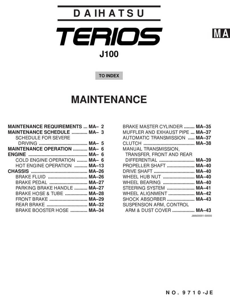
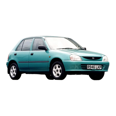
Daihatsu TERIOS J100 User manual

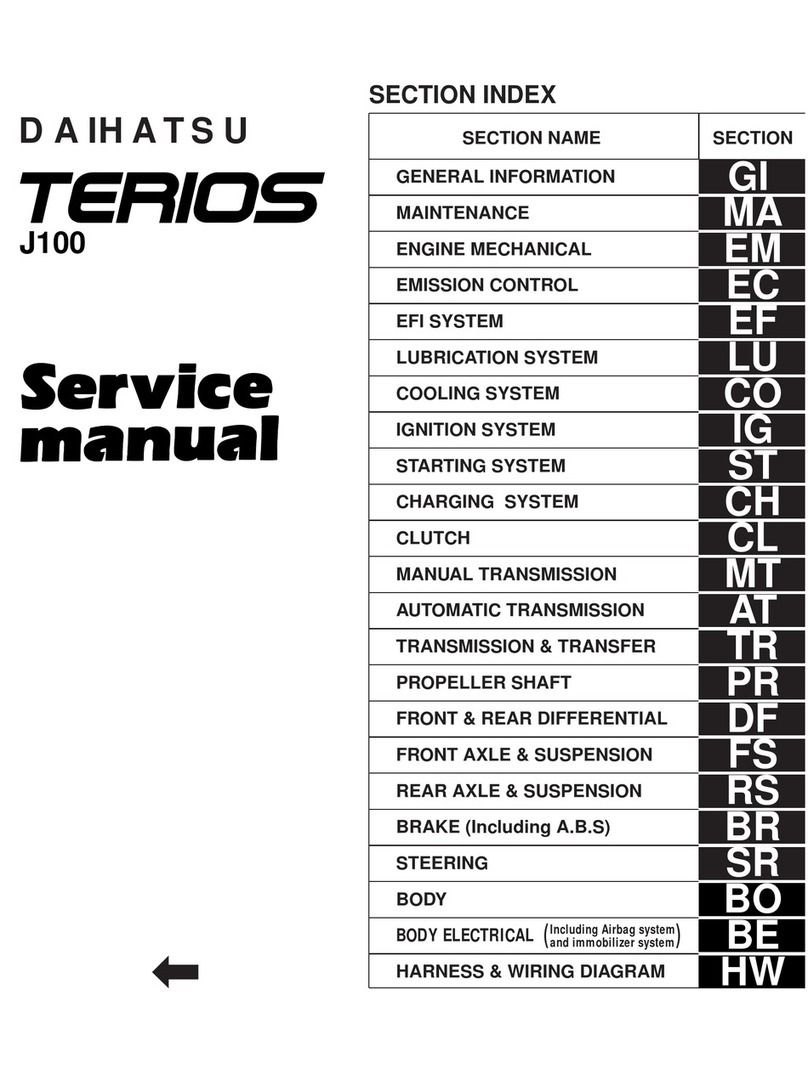
BODY
ALIGNMENT ADJUSTMENTS ................... BO– 2
FRONT BUMPER ........................................ BO– 7
FRONT FENDER ........................................ BO–11
REAR BUMPER .......................................... BO–13
FENDER LINER .......................................... BO–16
HOOD & HOOD LOCK CONTROL
CABLE .................................................... BO–18
FUEL LID OPENER .................................... BO–22
ROOF DRIP MOLDING ............................... BO–24
ROOF RAIL & ROOF END SPOILER ......... BO–25
REMOVABLE ROOF ................................... BO–28
INSTRUMENT PANEL ................................ BO–30
FRONT SEAT .............................................. BO–37
REAR SEAT ................................................ BO–39
SEAT BELT ................................................. BO–40
FRONT DOOR ............................................ BO–44
REAR DOOR ............................................... BO–52
BACK DOOR ............................................... BO–59
TRIM & GARNISH ....................................... BO–64
WINDOWS ................................................... BO–70
FUEL TANK ................................................ BO–82
ACCELERATOR PEDAL ............................. BO–91
EXHAUST PIPE .......................................... BO–93
ENGINE MOUNTING INSULATOR ............. BO–94
TIGHTENING TORQUE .............................. BO–96
DAIHATSU
BO
JBO00001-00000
NO. 9710-JE
NOTE:
·When the tightening torque values are not given, refer to the tightening torque table for general standard bolts to find the re-
quired tightening torque values.
J100
TO INDEX

ALIGNMENT ADJUSTMENTS
BO–2
q
e
r
t
w
r
y
u
200 mm
400 mm
i
JBO00002-00001
qSpecified value
Gap: 4.4 ±1.5 mm
Lateral deviation: Not to exceed 1.5 mm
Difference between right and left sides:
Not to exceed 1.5 mm
wSpecified value
Gap: 4.7 ±1.5 mm
Lateral deviation: Not to exceed 1.5 mm
Difference in height: 0 ±1.5 mm
eSpecified value
Gap: 7.6 ±1.5 mm
Difference between right and left sides:
Not to exceed 2.0 mm
Difference in height: 2.9 ±1.5 mm
rSpecified value
Gap: 5.5 ±1.5 mm
Lateral deviation: Not to exceed 1.5 mm
Difference in height: 0 ±1.5 mm
tSpecified value
Gap: 4.7 ±1.5 mm
Lateral deviation: Not to exceed 1.5 mm
Difference in height: 0 ±1.5 mm
ySpecified value
Gap: 5.2 ±1.5 mm
Lateral deviation: Not to exceed 1.5 mm
Difference in height: 5.9 ±1.5 mm
uSpecified value
Gap: 5.2 ±1.5 mm
Lateral deviation: Not to exceed 1.5 mm
Difference in height: 7.2 ±1.5 mm
iSpecified value
Gap: 7.8 ±1.5 mm
Difference between right and left sides:
Not to exceed 2.0 mm
Difference in height: 5.2 ±1.5 mm

1. Gap adjustment
Engine hood
(1) Loosen the bolts attaching the engine hood to the en-
gine hood hinge and adjust the engine hood alignment
to the specified value mentioned below.
Specified Value:
Gap: 4.4 ±1.5 mm
Difference Between Right and Left Sides:
Not to exceed 1.5 mm
Lateral Deviation: Not to exceed 1.5 mm
(2) Tighten the engine hood attaching bolts properly.
2. Adjustment of difference in height
(1) Loosen the bolts attaching the hood lock to the radia-
tor supports.
(2) Adjust the hood lock attaching position to adjust the
difference in height to the specified value.
At the same time adjust the height of the hood cushion
rubber so that the clearance between the engine hood
and the cushion rubbers may become zero and the
height at the right and left sides may become the
same.
Specified Value of Difference in Height:
Not more than 1.5 mm
ADJUSTMENT OF FRONT DOOR AND REAR
DOOR
1. Gap adjustment
(1) Front door
qLoosen the attaching bolts of the door hinges,
using the following SST.
SST: 09812-00010-000
CAUTION:
·Never scratch the painted surface of the body during
the operation.
wPerform the adjustment by changing the attaching
position of the front door hinges to the body.
eTighten the attaching bolts of the door hinge, using
the following SST.
SST: 09812-00010-000
rAdjust the door lock striker, as required.
(2) Rear door
qLoosen the attaching bolts of the door hinge.
wPerform the adjustment by changing the attaching
position of the rear door hinges to the body.
eTighten the attaching bolts of the door hinge.
rAdjust the door lock striker, as required.
BO–3
SST
JBO00003-00002
JBO00004-00003
JBO00005-00004
JBO00006-00005
2. Adjustment of difference in height
(1) Front/Rear door hinge side.
qLoosen the bolts attaching the door to the door
hinges.
wPerform the adjustment by changing the attaching
position of the front door to the door hinges.
eTighten the bolts attaching the door to the door
hinge.
BO–4
(2) Front/Rear door lock striker side.
qLoosen the screws of the lock striker.
wPerform the adjustment of the lock striker by tap-
ping it lightly with a hammer to change the attach-
ing position of the lock striker.
eTighten the attaching bolts of the lock striker.
Front
Rear
JBO00007-00006
JBO00000-00007
JBO00008-00008

ADJUSTMENT OF BACK DOOR ALIGNMENT
1. Gap Adjustment
(1) Loosen the attaching bolts of the hinge to the back
door.
(2) Perform the adjustment by changing the attaching po-
sition of the door panel.
If any difficulty is encountered in adjusting the attach-
ing position of the back door due to lack of adjusting
allowance, perform the adjustment by loosening the
nuts attaching the back door hinge to the vehicle shell
after the three grommets of the roof head lining are re-
moved.
NOTE:
·Be very careful not soil or bend the roof head lining
during the loosening of the nuts attaching the hinge to
the vehicle shell.
(3) Tighten the attaching bolts of the hinge to the back
door.
BO–5
100 mm
100 mm
q
w
e
t
r
JBO00009-00009
JBO00010-00010
qSpecified value
Gap: Door hinge section 10.4 ±2.0 mm
Lateral deviation: Not to exceed 2.0 mm
Difference in height: 1.8 ±2.0 mm
wSpecified value
Gap: 2.0 ±1.5 mm
Lateral deviation: Not to exceed 1.5 mm
Difference in height: 1.5 ±1.5 mm
eGap: 6.8 ±1.5 mm
Lateral deviation: Not to exceed 1.5 mm
Difference in height: 0 ±1.5 mm
rGap: 6.8 ±1.5 mm
Lateral deviation: Not to exceed 1.5 mm
Difference in height: 0 ±1.5 mm
tGap: 7.3 ±2.0 mm
Lateral deviation: Not to exceed 2.0 mm

2.Adjustment of difference in height
(1)Remove the rear bumper.
(Refer to the rear bumper section.)
(2)Remove the right hand side rear combination lamp.
(3)Remove the rear bumper filler by removing the attach-
ing bolts.
(4)Loosen the attaching bolts of the back door lock strik-
er.
(5)Adjust the difference in height by changing the attach-
ing position of the back door lock striker.
(6)Tighten the attaching bolts of the back door lock strik-
er.
BO–6
3.Back door lock striker side
(1)Loosen the screws of the lock striker.
(2)Perform the adjustment of the lock striker by tapping it
lightly with a hammer to change the attaching position
of the striker.
(3)Tighten the attaching bolts of the striker.
4.Adjustment of back door lower female stopper
(1)Loosen the attaching bolts of the back door lower fe-
male stopper to just only move the back door lower fe-
male stopper.
(2)Close the back door slowly.
(3)Open the back door slowly.
(4)Tighten the attaching bolts of the back door down fe-
male stopper.
(5)Ensure that the back door down female stopper is not
interfered with the down male stopper by repeating the
opening and closing operations of the back door.
JBO00011-00011
JBO00012-00012
JBO00013-00013

FRONT BUMPER
COMPONENTS
BO–7
yu
i
y
t
!9
w
w
e
r
@0
q
o
!3
!4
!5
!6
!7
!8
!1 !2
!0
JBO00014-00014
qFront bumper cover
wFront bumper guard base No. 1 bracket
eFront bumper guard right bracket
rFront bumper guard left bracket
tNo. 1 clip
yRadiator grill assembly
uRetainer
iGrill retainer
oFront bumper guard garnish subassembly
!0 Front turn signal lamp assembly
!1 Front turn signal lamp lens
!2 Bulb
!3 Front fog & turn lamp assembly
!4 Turn cord
!5 Bulb
!6 Fog cord
!7 Bulb
!8 Front fog & turn lamp lens
!9 Front bumper right bracket
@0 Front bumper left bracket

REMOVAL
1. Removal of front fog & turn signal lamp assembly (Only for
front bumper guard garnish equipped model.)
(1) Remove the fog lamp attaching screws.
(2) Remove the fog lamps by disconnecting its connec-
tors.
BO–8
2. Remove the under fender bracket by removing the attach-
ing tapping screw and clip. (Both sides)
3. Removal of radiator grill
(1) Turn the clips 90 degrees, using a phillips screwdriver.
(Four clips at the upper side of the radiator grill.)
(2) Remove the radiator grill assembly while unlocking the
locking section of the four clips and one retainer.
4. Removal of front turn signal lamps (On model without front
bumper guard garnish.)
(1) Remove the attaching screw of the front turn signal
lamps.
CAUTION:
·Be very careful not to scratch the lamps during the re-
moval and installation.
(2) Remove the front turn signal lamp by disconnecting
the connector.
Turn in a right
or left direction.
90¡90¡
Lock clip Retainer Lock clip
JBO00015-00015
JBO00016-00016
JBO00017-00017
JBO00018-00018
JBO00019-00019

5. Remove the attaching bolts of the front bumper cover. (On
model without the front bumper guard garnish.)
6. Remove the front bumper cover. (On model without the
front bumper guard garnish.)
7. Remove the front bumper bar reinforcement by removing
the attaching bolts. (On model without the front bumper
guard garnish.)
8. Remove the front bumper cover by removing the five at-
taching bolts. (Only model equipped with the front bumper
guard garnish.)
9. Remove the front bumper guard garnish by removing the
attaching screws. (On model with the front bumper guard
garnish.)
10. Remove the front bumper guard base bracket by remov-
ing the attaching bolts. (On model with the front bumper
guard garnish.)
INSTALLATION
NOTE:
·Basically the installation procedure is reverse to the removal procedure. Therefore, illustrations are
not given in this installation procedure. Refer to the illustrations in the removal procedure in cases
where any difficulty is encountered.
1. Install the front bumper guard base brackets with the attaching bolts. (On model with the front bumper
guard garnish.)
2. Install the front bumper guard garnish to the front bumper cover with the attaching screws. (On model
with the front bumper guard garnish.)
3. Install the front bumper cover with the five attaching bolts. (Only model equipped with the front bumper
guard garnish.)
4. Install the front bumper bar reinforcement with the attaching bolts. (Only model without the front bumper
guard garnish.)
5. Install the front bumper cover with the attaching bolts. (Only model without the front bumper guard gar-
nish.)
6. Installation of front turn signal lamps (Only model without the front bumper guard garnish.)
(1) Connect the connector of the front turn signal lamps.
(2) Install the attaching screw of the front turn signal lamps.
BO–9
JBO00020-00020
JBO00021-00021
JBO00022-00022

7. Installation of radiator grill
(1) Ensure that the clips and retainer are installed properly. Also, ensure that no damage exists.
If any damage exists or the clip or retainer is missing, replace the clips or retainer with a new one.
(2) Install the radiator grill by connecting the retainer and four clips.
(3) Lock the clips by turning the head section of the clip, using a phillips screwdriver. (Four portions)
8. Install the under fender bracket by installing the attaching tapping screw and grommet. (Both sides)
9. Installation of front fog & turn signal lamp (Only model equipped with the front bumper guard garnish.)
(1) Connect the connectors of the wire harness to the fog lamps.
(2) Install the fog lamp with the attaching screws.
BO–10
JBO00023-00000

FRONT FENDER
COMPONENTS
REMOVAL
1. Remove the front bumper cover.
(Refer to the front bumper section.)
2. Remove the front mudguard by removing the three attach-
ing bolts.
3. Remove the front fender liner attaching screw grommets.
(Refer to the front fender liner section.)
BO–11
q
w
y
ii
e
e
r
t
o
!1
!0
u
JBO00024-00023
JBO00025-00024
qHood subassembly
wHood silencer
eClip
rHeadlamp cover to hood seal (R, L)
tClip
yHood to front end panel seal
uHood front protector
iFront fender subassembly (R, L)
oFront fender liner
!0 Clip
!1 Over fender

BO–12
4.Remove the over fender from the fender panel by discon-
necting the retainers while retracting the lock section,
using a nosepliers or the like.
5.Remove the side turn signal lamp.
6.Remove the front fender subassembly by removing the
five attaching bolts.
JBO00026-00025
A
A
A - A
INSTALLATION
NOTE:
•Basically the installation procedure is reverse to the removal procedure. Therefore, illustrations are
not given in this installation procedure. Refer to the illustrations in the removal procedure in cases
where any difficulty is encountered.
1.Install the front fender subassembly with the attaching bolts and tighten them properly.
2.Install the side turn signal lamp.
3.Installation of over fender
(1)Ensure that the retainers are installed properly and there is no damage.
If any damage exists, replace the retainer with a new one.
(2)Install the over fender to the front fender by connecting the retainers on the over fender to the front
fender.
(3)Ensure that the retainers are locked properly.
4.Install the front fender liner. (Refer to the fender liner section.)
5.Install the front mudguard with the three attaching bolts.
6.Install the front bumper. (Refer to the front bumper section.)
JBO00027-00000

REAR BUMPER
COMPONENTS
REMOVAL
1. Remove the rear bumper filler and quarter panel mud-
guard (when equipped) by removing the attaching screw
grommets.
2. Remove the rear bumper cover attaching bolt. (Both sids)
3. Removal of back-up lamp(s) and rear fog lamp (when
equipped)
(1) Remove the attaching screw.
(2) Remove the back-up lamp assembly(s) and rear fog
lamp (when equipped) by disconnecting their connec-
tor.
BO–13
w
y
y
u
q
t
t
r
re
o !0 !1
i
JBO00028-00026
JBO00029-00027
JBO00030-00028
qRear bumper cover
wLicense plate bracket base
eRear bumper filler
rRear bumper right protector
tLower back panel cover
yLicense plate lamp assembly
uQuarter panel mudguard subassembly
iBack-up lamp and/or rear fog lamp
oRear combination lamp socket
!0 Bulb
!1 Rear lamp lens

4.Remove the license plate lamps by retracting the lock
sections of the license plate lamps from the rear bumper
cover.
5.Disconnect the license plate lamps from the connectors.
BO–14
6.Remove the rear bumper cover and license plate bracket
base (when equipped) by removing the eight attaching
bolts.
7.Remove the lower back panel cover and air vent.
(If necessary.)
8.Removal of rear combination lamp
(1)Remove the two attaching bolts and one screw.
(2)Remove the rear combination lamp by disconnect the
connector of the wire harness.
9.Remove the rear bumper filler by removing the two attach-
ing bolts.
JBO00031-00029
JBO00032-00030
JBO00033-00031
JBO00034-00032
JBO00035-00033

INSTALLATION
NOTE:
·Basically the installation procedure is reverse to the removal procedure. Therefore, illustrations are
not given in this installation procedure. Refer to the illustrations in the removal procedure in cases
where any difficulty is encountered.
1.Install the rear bumper filler with the two attaching bolts.
2.Installation of rear combination lamp
(1)Connect the connector of the wire harness to the rear combination lamp.
(2)Install the two attaching bolts and one screw.
3.Install the lower back panel cover and air vent. (If it has been removed.)
4.Install the rear bumper cover and license plate bracket base (when equipped) with the eight attaching
bolts.
5.Install the rear bumper cover attaching screws to the fender covers and body panel at both sides.
6.Connect the license plate lamps to the connectors.
7.Install the license plate lamp(s) to the rear bumper cover and ensure that the lock section of the license
plate lamps is engaged to the rear bumper cover.
8.Install the back-up lamp(s) and rear fog lamp.
(1)Connect the connector of the wire harness to the back-up lamp(s) and fog lamp (when equipped).
(2)Install the back-up lamp(s) and fog lamp (when equipped) with the attaching screw.
9.Install the rear bumper filler and quarter panel mudguard with the attaching screw grommets.
BO–15
JBO00036-00000

FENDER LINER
COMPONENTS
BO–16
REMOVAL
1. Remove the front fender mudguard subassembly by re-
moving the three attaching bolts.
2. Remove the under fender bracket by removing the grom-
met and tapping bolt.
q
w
t
r
e
JBO00037-00034
JBO00038-00035
JBO00039-00036
qFront fender liner
wClip
eFront fender mudguard subassembly
rGrommet
tFront bumper bracket

3. Remove the screw grommet for the tapping bolts by cut-
ting off the hem section of the grommet as shown.
4. Remove the ten screw type grommets by screwing them
out.
5. Remove the front fender liner.
INSTALLATION
NOTE:
·Basically the installation procedure is reverse to the removal procedure. Therefore, illustrations are
not given in this installation procedure. Refer to the illustrations in the removal procedure in cases
where any difficulty is encountered.
1. Install the front fender liner with the ten screw grommets.
NOTE:
·Insert the fender liner into between the fender panel and the over fender at the three screw grommet
installing positions.
·Install the three screw grommets for tapping bolts to the lower side of the fender liner.
2. Install the under fender bracket with the attaching grommet and tapping screw.
3. Install the front fender mudguard with the three attaching bolts.
BO–17
,
,
,
,
,
Screw
grommet
Cut
JBO00040-00037
JBO00041-00038
JBO00042-00000

HOOD & HOOD LOCK CONTROL CABLE
COMPONENTS
BO–18
Removal of engine hood
1. Disconnect the window washer hose from the window
washer nozzle(s), clamps of the engine hood and clamp.
2. Remove the window washer nozzles from the engine hood
by retracting the lock sections of the window washer noz-
zles.
q
r
w
e
e
y
t
JBO00043-00039
JBO00044-00040
JBO00045-00041
qHood lock control cable assembly
wHood lock assembly
eHood hinge assembly (R, L)
rHood support rod
tHood support clamp
yClip

3. Remove the insulator, the hood-to-front end panel seal and
the head lamp cover-to-hood seal by removing the attach-
ing retainers.
4. Place cloths under the engine hood in order to prevent the
painted surface from being damaged.
5. Loosen the attaching bolts of the engine hood which are
connected to the hood hinges.
6. Remove the engine hood by removing the attaching bolts
while supporting the engine hood securely.
7. Removal of engine hood hinge
(1) Remove the front fender.
(Refer to the front fender section.)
(2) Remove the engine hood hinge by removing the at-
taching bolts.
Installation of the engine hood
NOTE:
·Basically the installation procedure is reverse to the removal procedure. Therefore, illustrations are
not given in this installation procedure. Refer to the illustrations in the removal procedure in cases
where any difficulty is encountered.
1. Installation of engine hood hinge
(1) Install the engine hood hinge with the attaching bolts.
(2) Install the front fender. (Refer to the front fender section.)
2. Place a piece of cloth under the engine hood in order to prevent the painted surface from being dam-
aged.
3. Install the engine hood with the attaching bolts while supporting the engine hood securely.
4. Tighten the bolts attaching the engine hood to the hood hinges temporarily.
5. Remove the cloth.
6. Perform the adjustment of the engine hood alignment.
7. Install the insulator, the hood-to-front end panel seal and the head lamp cover-to-hood seal with the at-
taching clips.
8. Install the window washer nozzles to the engine hood.
9. Install the window washer hoses to the engine hood.
10. Connect the window washer hoses to the window washer nozzle. Tighten the attaching bolts of the en-
gine hood which are connected to the hood hinges.
BO–19
JBO00046-00042
JBO00047-00043
JBO00048-00044
JBO00049-00000

Removal of hood lock and hood lock control cable
1. Remove the radiator grill.
(Refer to the front bumper section.)
2. Remove the front fender liner.
(Refer to the front fender liner section.)
3. Removal of hood lock assembly
(1) Remove the three attaching bolts of the hood lock as-
sembly.
(2) Remove the hood lock assembly by disconnecting the
hood control cable.
BO–20
6. Remove the two attaching bolts of the hood lock control
handle bracket.
7. Remove the cowl side trim board subassembly. (Refer to
the BO section.)
8. Remove the hood lock control cable assembly from the
vehicle.
NOTE:
·For easier operation to reinstall the hood lock control
cable, connect a suitable string to the end of the hood
lock control cable before the removal.
A
A
B
Front apron member
To upper cowl side
Wire harness
Extension apron fender side
Apron front fender
Clamp Control cable
Cross section A - A Clamp
(Clamped together with wire harness)
Apron fender
JBO00050-00045
JBO00051-00046
JBO00052-00000
4. Remove the cowl side trim board assembly.
(Refer to the trim & garnish section.)
5. Release the control cable from the clamps.
Other manuals for TERIOS J100
1
Table of contents
Other Daihatsu Automobile manuals

Daihatsu
Daihatsu G200 User manual

Daihatsu
Daihatsu S85 Instruction manual

Daihatsu
Daihatsu Mira User manual

Daihatsu
Daihatsu F300 User manual

Daihatsu
Daihatsu S85 Manual

Daihatsu
Daihatsu 1978 Charade Manual

Daihatsu
Daihatsu F300 Instruction manual

Daihatsu
Daihatsu TERIOS J100 Guide

Daihatsu
Daihatsu 1997 Terios J100 User manual