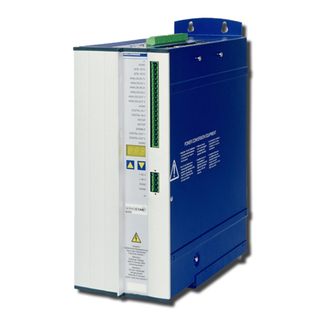
Danaher Motion Kollmorgen SERVOSTAR SP3 User manual

Danaher Motion
SERVOSTAR® SP3 Power Block
Installation Manual
KOLLMORGEN
giving our customers freedom of design
M-SS-010-0104
www.szcxi.com | From :KOLLMORGEN

Record of Manual Revisions
ISSUE NO. DATE REVISIONS
1 08/01/01 Initial Release
2 01/16/02 Correction to AC wiring description; addition of Watchdog description
3 February, 2003 Rename connector C8 to C5
Hardware spec: remove reference to C7 (Weidmuller)
Troubleshooting: add description of “F” fault (PWM Frequency)
4 February, 2003 Maximum PWM frequency is 15.5kHz
Added definition of C5 mating connector
Copyright Information
Copyright 2001 Kollmorgen - All rights reserved.
NOTICE:
This document is proprietary information of Kollmorgen that is furnished for customer use
ONLY. No other uses are authorized without written permission of Kollmorgen. Information in
this document is subject to change without notice and does not represent a commitment on the
part the Kollmorgen Corporation. Therefore, information contained in this manual may be
updated from time-to-time due to product improvements, etc., and may not conform in every
respect to former issues.
Not for use or disclosure outside of Kollmorgen except under written agreement. All rights are
reserved. No part of this book shall be reproduced, stored in retrieval form, or transmitted by any
means, electronic, mechanical, photocopying, recording, or otherwise without the written
permission from Kollmorgen. While every precaution has been taken in the preparation of the
book, the publisher assumes no responsibility for errors or omissions. Neither is any liability
assumed for damages resulting from the use of the information contained herein.
Kollmorgen GOLDLINE®, SILVERLINE®, PLATINUM®, and SERVOSTAR®are a
registered trademarks of the Kollmorgen Corporation. PMAC® and Accessory 8F®are registered
trademarks of Delta Tau Data Systems, Inc.
www.szcxi.com | From :KOLLMORGEN

Safety Instructions
Only qualified personnel are permitted to transport, assemble, commission, and maintain this equipment.
Properly qualified personnel are persons who are familiar with the transport, assembly, installation,
commissioning and operation of motors, and who have the appropriate qualifications for their jobs. The
qualified personnel must know and observe the following standards and regulations:
IEC 364 resp. CENELEC HD 384 or DIN VDE 0100
IEC report 664 or DIN VDE 0110
National regulations for safety and accident prevention or VBG 4
Read all available documentation before assembling and commissioning. Incorrect handling of products
in this manual can result in injury and damage to persons and machinery. Strictly adhere to the technical
information regarding installation requirements.
It is vital to ensure that all system components are connected to earth ground. Electrical safety is
provided through a low-resistance earth connection.
The SERVOSTAR®product contains static sensitive components that can be damaged by incorrect
handling. Avoid contact with high insulating materials (artificial fabrics, plastic film, etc.). Place the
product on a conductive surface. Ground yourself (discharge any possible static electricity build-up) by
touching an unpainted, metal, grounded surface.
Keep all covers and cabinet doors shut during operation. Otherwise, potential hazards could cause severe
personal injury or damage to the product.
Be aware that during operation, the product has electrically charged components and hot surfaces.
Control and power cables can carry a high voltage, even when the motor is not rotating.
Never disconnect or connect the product while the power source is energized to avoid electric arcing and
hazards to personnel and electrical contacts.
After removing the power source from the equipment, wait at least 10 minutes before touching or
disconnecting sections of the equipment that normally carry electrical charges (e.g., capacitors, contacts,
screwed connections). To be safe, measure the electrical contact points with a meter before touching the
equipment.
Safety symbols indicate a potential for personal injury or equipment damage if the recommended
precautions and safe operating practices are not followed. Read and be familiar with the safety notices in
this manual before attempting installation, operation, or maintenance to avoid serious bodily injury,
damage to the equipment, or operational difficulty. The safety-alert symbols are:
"Warning" identifies hazards that could result in personal injury or death.
"Caution" identifies hazards that could result in personal injury or equipment
damage.
"Note" identifies information required for your understanding or use of the
equipment.
www.szcxi.com | From :KOLLMORGEN

Directives and Standards
The SERVOSTAR®SP3 Power Block has been successfully tested and evaluated to meet UL/cUL 508C
for the U.S. and Canadian markets. This standard outlines the minimum requirements for electrically
operated power conversion equipment (frequency converters and servo amplifiers), which are intended to
eliminate the risk of fire, electric shock, or injury to persons, being caused by such equipment.
CE Mark Conformance
Servo drives are incorporated in electrical plants and machines for industrial use. When the servo drives
are built into machines or plants, the operation of the drive is prohibited until the machine or plant meets
the requirements of the EC Directive on Machines 89/392/EEC and the EC Directive on EMC
(89/336/EEC). Directives EN 60204 and EN 292 must also be met.
In connection with the Low Voltage Directive 73/23/EEC, the harmonized standards of the EN 50178
series are applied to the amplifiers, together with EN 60439-1, EN 60146 and EN 60204.
The manufacturer of the machine or plant is responsible for ensuring that they meet the limits; which are
required by the EMC regulations. Advice on the correct installation for EMC - such as shielding,
grounding, arrangement of filters, treatment of connectors and the lay out of cabling can be found in this
documentation.
Conformance with the EC Directive on EMC 89/336/EEC and the Low Voltage Directive 73/23/EEC is
mandatory for the supply of servo drives within the European Community.
The servo drives have been tested by an authorized testing laboratory in a defined configuration with the
system components deSP3 Power Blockribed in this documentation. Kollmorgen is not responsible for
any divergence from the configuration and installation deSP3 Power Blockribed in this documentation
and is not responsible for the performance of new measurements or ensuring that regulatory requirements
are met.
Kollmorgen’s SERVOSTAR SP Power Block has been successfully tested and evaluated to the limits
and requirements of the EC Directive on EMC (89/336/EEC) and the EC Directive on Low Voltage
(72/73/EEC). The product lines have been evaluated to EN50178 and EN60204 as a component of a
machine and other relevant standards.
The Electromagnetic Compatibility (EMC) of a system is identified in two parts: emissions and
immunity. Emission refers to the generation of electromagnetic interference (EMI), and immunity refers
to the suSP3 Power Blockeptibility levels of the equipment. Limits are derived from generic standards
EN55081-2 and EN55082-2 for heavy industrial environment. The SERVOSTAR series of drives and
bus modules have been tested for radiated emissions, conducted emissions, EFT, ESD, surge, conducted
immunity, and radiated immunity. These tests have been in accordance with EN55011, EN61000-4-2,
ENV50140, IEC 1000-4-4, EN61000-4-5, and ENV50141.
Installation of the equipment is critical in designing system and machine
electromagnetic compatibility (EMC). The user must apply the installation
recommendations in this manual (see the sections on Installation and CE
Filtering Techniques when mounting and installing the drive system for CE
conformance.
www.szcxi.com | From :KOLLMORGEN

Kollmorgen Safety Instructions
SERVOSTAR®SP3 Power Block i
Table of Contents
READ BEFORE INSTALLING...................................................................................................1
UNPACKING AND INSPECTING..............................................................................................3
WARRANTY INFORMATION ............................................................................................................3
USE AS DIRECTED ..........................................................................................................................3
PART NUMBER...............................................................................................................................4
ELECTRICAL SPECIFICATIONS ........................................................................................................5
MOUNTING...................................................................................................................................7
HARDWARE SPECIFICATIONS .........................................................................................................7
OUTLINE DIMENSIONS ...................................................................................................................8
MOUNTING PRACTICES ..................................................................................................................8
CE FILTERING TECHNIQUES ..........................................................................................................9
Input Power Filtering................................................................................................................9
Motor Line Filtering ...............................................................................................................10
I/O Filtering ............................................................................................................................11
GROUNDING.................................................................................................................................12
BONDING .....................................................................................................................................12
Non-insulated Cable Clamp....................................................................................................13
Alternative Bonding Methods..................................................................................................13
SYSTEM WIRING ......................................................................................................................15
MAIN POWER CONNECTOR ..........................................................................................................15
24V LOGIC POWER CONNECTOR (OPTIONAL)..............................................................................16
STANDARD OPTION......................................................................................................................17
Standard Option Block Diagram.............................................................................................18
INTEGRATED 8F OPTION CONNECTOR .........................................................................................18
Integrated 8F Option Block Diagram .....................................................................................19
SYSTEM INTERCONNECT...............................................................................................................19
Connector C1: Hall Effect Device Feedback ..........................................................................19
Connector C2: Encoder Feedback..........................................................................................20
Connector C3: PMAC Interface..............................................................................................21
Connector C4: User Flags ......................................................................................................22
Connector C5 User Flags .......................................................................................................22
DIP SWITCHES ......................................................................................................................22
TROUBLESHOOTING ..............................................................................................................23
DISPLAY ......................................................................................................................................23
WATCHDOG .................................................................................................................................24
F FAULT (MAXIMUM PWM FREQUENCY) ....................................................................................24
FAULT CODE TRANSMISSION .......................................................................................................24
OVER-CURRENT SHUT-DOWN......................................................................................................25
www.szcxi.com | From :KOLLMORGEN

Kollmorgen Safety Instructions
SERVOSTAR®SP3 Power Block ii
CURRENT SCALING ......................................................................................................................25
CUSTOMER SUPPORT ...................................................................................................................26
www.szcxi.com | From :KOLLMORGEN
Kollmorgen Read Before Installing
SERVOSTAR®SP3 Power Block 1
READ BEFORE INSTALLING
This manual is provided with your product to assist you in getting your SERVOSTAR®SP3
Power Block installed and operational.
High voltage can be hazardous to personnel and equipment. Be sure a qualified
electrician works on this equipment. To ensure safety, follow all national and local
codes during installation as well as the safety precautions outlined in the front of
this documentation.
1. Open the box(es) and remove all the contents. Check to ensure there is no visible damage
to any of the equipment.
2. Mount the SP3 Power Block to the back panel. Refer to the Outline Dimensions for
additional details. Metal-to-metal contact is important for electrical noise control!
3. Wire the SP3 Power Block according to the System Wiring Diagram. Pay particular
attention to the pinout connector details.
4. Connect solid earth ground to frames of all components.
5. Wire the main power (24 VDC).
6. Wire the motor and feedback. Refer to the Feedback Wiring Diagram for additional
information.
7. Wire the Regen Resistor kit, if applicable.
8. Verify that all wiring is correct.
9. Verify that earth grounds are connected.
10. Verify all electrical and safety codes are met.
11. For the integrated 8F option:
A. Connect the halls cable to connector C1.
B. Connect the feedback connector C2.
C. Connect the connector C3 to PMAC (The SP3 works with the standard PMAC
motion controller).
D. Connect the user flags connector C4.
E. Connect the user flags connector C5.
www.szcxi.com | From :KOLLMORGEN

Kollmorgen Read Before Installing
SERVOSTAR®SP3 Power Block 2
12. For the Standard option:
A. Connect the cable C2.
B. Connect the 8F Delta Tau accessory.
13. Configure the SP3 Power Block for your particular motor, if this was not done at the
factory.
14. Tune the SP3 Power block for the load and desired performance.
15. Enable the system.
www.szcxi.com | From :KOLLMORGEN

Kollmorgen Unpacking and Inspecting
SERVOSTAR®SP3 Power Block 3
UNPACKING AND INSPECTING
Open the box and remove all the contents. Check to ensure there is no visible damage to any of
the equipment.
Electronic components in this amplifier are design-hardened to reduce static
sensitivity. However, proper procedures should be used when handling to avoid
damage to equipment.
Remove all packing material and equipment from the shipping container. Be aware
that some connector kits and other equipment pieces may be quite small and can be
accidentally discarded if care is not observed when unpacking the equipment. Do not
dispose of shipping materials until the packing list has been checked.
Upon receipt of the equipment, inspect components to ensure that no damage has
occurred in shipment. If damage is detected, notify the carrier immediately. Check all
shipping material for connector kits, documentation, diskettes, CD-ROM, or other
small pieces of equipment.
WARRANTY INFORMATION
All products covered in this manual are warranted to be free of defects in material and
workmanship and to conform to the specifications stated either in this document or product
catalog description. All Kollmorgen brushless motors and electronics are warranty for a period of
24 months from the time of installation or 30 months from time of shipment, which ever comes
first. There are no other warranties, expressed or implied (including the warranty of
merchantability and fitness for a particular purpose, which extends beyond this warranty.
Kollmorgen warrants that the products covered in the manual are free from patent infringement
when used for normal purposes.
USE AS DIRECTED
The following guidelines describe the restrictions for proper use of the SERVOSTAR SP3
Power Block:
1. The amplifiers are components built into electrical equipment or machines and can only
be used as integral components of such equipment.
2. The servo amplifiers are to be used only on earthed three-phase industrial mains supply
networks (TN-system, TT-system with earthed neutral point).
3. The servo amplifiers must not be operated on power supply networks without an earth or
with an asymmetrical earth.
4. If the servo amplifiers are used in residential areas, or in business or commercial
premises, you must implement additional filter measures.
5. The servo amplifiers are only intended to drive brushless synchronous servomotors with
closed-loop control of torque, speed, and position. The rated voltage of the motors must
be at least as high as the DC-link voltage of the servo amplifier.
www.szcxi.com | From :KOLLMORGEN

Kollmorgen Unpacking and Inspecting
SERVOSTAR®SP3 Power Block 4
6. The servo amplifiers may only be operated in a closed switch gear cabinet, taking into
account the ambient conditions defined in the environmental specifications.
7. Danaher Motion Kollmorgen guarantees the conformance of the servo amplifiers with the
standards for industrial areas stated in the front of this manual only if Danaher Motion
Kollmorgen delivers the components (motors, cables, amplifiers etc).
PART NUMBER
CP3 03 25 8
Current Rating
03: 3 Amp. continuous; 9 Amp. peak
06: 6 Amp. continuous; 18 Amp. peak
10: 10 Amp. continuous; 20 Amp. peak
Product Designator
SERVOSTAR SP3 Model Number
0: without 8F
1: with integrated 8F
25: logic power generated internally
26: 24V external logic power
www.szcxi.com | From :KOLLMORGEN

Kollmorgen Unpacking and Inspecting
SERVOSTAR®SP3 Power Block 5
ELECTRICAL SPECIFICATIONS
Product Model CP303 CP306 CP310
Voltage (VacL-L) Nominal ±10% 110-230 230
115Vac 1φ/ 3φ1/3
230Vac 1φ/ 3φ1/3 3φonly
Line Frequency 47-63
KVA at 115 (1φ) 0.44 0.89
Continuous Current (amps) at 115VAC 3.9 7.7
Peak Current (amps) for 500 mSec 115VAC 11.7 23.1
Peak Current (amps) for 2 Sec 115AC 7.8 15.4
Main Input KVA at 230 (1φ) 0.89 1.8
Power Continuous Current (amps) at 230 (1φ) 3.9 7.7
Peak Current (amps) for 500mSec at 230 (1φ) 11.7 23.1
Peak Current (amps) for 2Sec at 230 (1φ) 7.8 15.4
Line Fuses (FRN-R, LPN, or equivalent) 10 20
KVA at 230 (3φ) 1.4 2.8 4.6
Continuous Current (amps) at 230 (3φ) 3.5 7 12
Peak Current (amps) for 500mSec at 230 (3φ) 10.5 21 36
Peak Current (amps) for 2Sec at 230 (3φ) 7 14 24
Line Fuses (FRN-R, LPN, or equivalent) 10 20 25
Logic Input +24VDC Ext. Logic Voltage (volts) 22 - 27
Power +24VDC Ext. Logic Current (amps sink) 0.5
SoftStart Max. Surge Current (amps) 30
Max. Charge Time (sec) 0.25
Fault Contact Rating 1A
Fault Contact Closing Period (mSec) Close = 3mS, Open = 2mS
OverTemperature trip (°C) 80°C
Protection UnderVoltage Trip (nominal) 90 VDC
Functions OverVoltage Trip 430 VDC
OverTemperature Trip 80°C
Internal heat dissipation (watts) 60 80 132
Continuous Power (KVA) at 115VAC 1φLine Input
(45°Ambient)
0.35 0.7
Continuous Power (KVA) at 230VAC 1φLine Input
(45°C Ambient)
0.7 1.4
Continuous Power (KVA) at 230VAC 3φLine
Input(45°Ambient)
1.1 2.2 3.5
Main Output Continuous Current (Arms) 3 6 10
(Ma, Mb, Mc) Peak Current (Arms) for 500 mSec 9 18 20
Peak Current (Arms) for 2 Sec 6 12 20
PWM Frequency (kHz) 15.5 8 8
PWM Motor Current Ripple (kHz) 31 16 16
Form Factor (rms/avg) ≤1.01
Operation temperature 5°C to 45°C
Storage temperature -0°C to 70°C
Environment Ambient humidity 10% to 90%
Atmosphere with no corrosive gasses or dust
Altitude Derate 5% per 1000-ft (300m) above
3300-ft (1000m)
Vibration 0.5 g
www.szcxi.com | From :KOLLMORGEN

Kollmorgen Unpacking and Inspecting
SERVOSTAR®SP3 Power Block 6
Regen Information
Product Model Cx03 Cx06 Cx10
External Shunt Peak current (amps) 20
Regulator Minimum resistance (Ω) 20
Watts 200
Capacitance (Farads) 0.00082 0.00164
Application BUS Voltage (nominal) (VDC) 325
Information VHYS (Regen circuit turn-off) (VDC) 370
VMAX (Regen circuit turn-on) (VDC) 390
External Regen Kits ERH-26 aaa
www.szcxi.com | From :KOLLMORGEN

Kollmorgen Mounting
SERVOSTAR®SP3 Power Block 7
MOUNTING
The SERVOSTAR system should be operated and stored under the environmental conditions
stated in the electrical specification tables. The system may be operated in higher temperature
ambient conditions with a derating applied. Check with the factory for derating information.
Attention to proper installation and field wiring are of prime importance to ensure long-term and
trouble-free operation. Follow the installation and wiring instructions in this document and
incorporate all applicable electrical and safety codes, laws, and standards.
HARDWARE SPECIFICATIONS
Amplifier Model CP303 CP306 CP310
Unit Weight lbs / Kgs 3.56 / 1.61 4.9 / 2.22 5.94 / 2.69
Mounting English (Metric) 10-32 (M4)
Hardware Applied Torque 20lb-in (2.26Nm)
Line Screw Size/Torque
Connection BUS Screw Size/Torque M3.5 / 12lb-in (1.35Nm)
Hardware Motor Screw Size/Torque
Ground Screw Size/Torque
Control Logic (AWG/ mm2) 28 – 16 / 0.5 – 1.5
Motor Line (AWG/ mm2) 14 / 0.25
Main Input (AWG/ mm2) 14 / .25 12 / 4
Configurable I/O wire gauge 22-18 AWG (.3-.75mm2) Ferrules recommended:
18 AWG Type H1 - 0/14 Weidmuller 4630.0 or equiv.
20 AWG Type H0 - 75/14 Weidmuller 4629.0 or equiv.
Wire Size
(AWG#)
Spade Terminals 16/14 AWG (1.5mm2): Hollingsworth XSS0954S or
SS20947SF or equivalent
12/10 AWG (4-6mm2): Hollingsworth XSS20836 or
SS20832F or equivalent
Ring Terminals 8 AWG (10mm2): Hollingsworth R3027BF or equiv.
6 AWG (16mm2): Hollingsworth R4001BF or equiv.
4 AWG (25mm2): Hollingsworth R5100BF or equiv.
2 AWG (35mm2): Hollingsworth R7998BFN or equiv.
Clearance Side-to-Side 0.5in (12.7mm)
Distance Top/Bottom 2.5in (63.5mm)
Mating CK100 Kit Includes: C1, C2, C4
Connector
Hardware
C3 Cable Kollmorgen P/N: CBL-00022000-00
Vendor Info: HIROSE HIF6H-50D-1.27R
C5 Connector Manufacturer: Weidmuller; PN 161570
Connector Screw Torque 2.25 lb-in (0.25m)
24V Logic (optional) PCD ELFP02210 or equiv.
www.szcxi.com | From :KOLLMORGEN

Kollmorgen Mounting
SERVOSTAR®SP3 Power Block 8
OUTLINE DIMENSIONS
2x
∅
10.0
[.39]
3 x 5.5
[.22]
36.5
[1.44]
15.5
[.61]
244.0
[9.61]
33.7
[1.33]
216.0
[8.50]
163.0
[6.42] 2.0
[.08]
256.0
[10.08]
88.4 [3.48]
HEAT SINK
CP3 06
CP3 03
67.4 [2.65]
6.7
[.61]
CP310
99.0 [3.90]
MOUNTING PRACTICES
The Kollmorgen SERVOSTAR series of electronic system components are designed for panel
assembly. This panel assembly is then mounted in a metallic enclosure. Enclosures are supplied
by the manufacturers of the final product and meet the environmental IP rating of the end
product. To ensure proper grounding (and to optimize EMC), the enclosure should have
continuous ground continuity maintained between all metal panels. This ground continuity is
intended to be both a safety ground and a high frequency ground. The units are mounted on a
back plane installed into the enclosure. Ideally, the back plane should be an unpainted metallic
surface to optimize electrical bonding of the frame and provide the lowest possible impedance
path to earth ground. These enclosures also provide added safety.
The SERVOSTAR units should be mounted vertically for proper ventilation. These products are
designed for mounting in an electrical enclosure to protect them from physical and environmental
damage.
www.szcxi.com | From :KOLLMORGEN

Kollmorgen Mounting
SERVOSTAR®SP3 Power Block 9
Particular care should be used when layout of an enclosure is designed. Separate power wires
from small signal wires. The following guidelines highlight some important wiring practices to
implement:
1. Control and signal cables must be separated from power and motor cables. Distance of
20cm (8 in.) is sufficient in most cases.
2. Control and signal cables must be shielded to reduce the effects of radiated interference.
3. When control cables must cross power or motor cables, they should cross at an angle of
90 degrees, if possible. This reduces the field coupling effect.
CE FILTERING TECHNIQUES
The SERVOSTAR system (power block, drive, motor) meets the CE Mark standards stated in
the front of this manual. Apply proper bonding and grounding techniques, described earlier in
this section, when incorporating EMC noise filtering components to meet this standard.
Noise currents often occur in two types. The first is conducted emissions passed through ground
loops. The quality of the system-grounding scheme inversely determines the noise amplitudes in
the lines. These conducted emissions are of a common-mode nature from line-to-neutral
(ground). The second is radiated high-frequency emissions that are usually capacitively coupled
from line-to-line and are differential in nature.
To properly mount the filters, the enclosure should have an unpainted metallic surface. This
allows for more surface area to be in contact with the filter housing and provide a lower
impedance path between the housing and the back plane. The back panel should have a high
frequency ground strap connection to the enclosure frame and earth ground.
Input Power Filtering
The Danaher Motion Kollmorgen SERVOSTAR electronic system components require EMI
filtering in the input power leads to meet the conducted emission requirements for the industrial
environment. This filtering blocks conducted-type emissions from exiting onto the power lines
and provides a barrier for power line EMI.
Adequately size the system. The type of filter must be based on the voltage and current rating of
the system and whether the incoming line is single- or three-phase. The implementation of the
EMI filter should be done in accordance with the following guidelines:
• Filter should be mounted on the same panel as the drive.
• Filter should be mounted as close as possible to incoming cabinet power.
• When mounting the filter to the panel, remove any paint or material covering. Use an
unpainted metallic back panel, if possible.
www.szcxi.com | From :KOLLMORGEN

Kollmorgen Mounting
SERVOSTAR®SP3 Power Block 10
• Filters are provided with an earth connection. All ground connections should be tied to
ground.
• Filters can produce high leakage currents. Filters must be earthed before connecting the
supply!
• Do not touch filters for a period of 10 seconds after removing the power supply.
Motor Line Filtering
Motor filtering may not be necessary for CE compliance of SERVOSTAR systems. However,
this additional filtering increases the reliability of the system. Poor non-metallic enclosure
surfaces and lengthy, unbonded (or unshielded) motor cables that couple noise line-to-line
(differential) are some of the factors that may lead to the necessity of motor lead filtering.
Motor lead noise is either common-mode or differential. The common-mode conducted currents
occurs between each motor lead and ground (line-to-neutral). Differential radiated currents exists
from one motor lead to another (line-to-line). The filtering of the lines feeding the motor
provides additional attenuation of noise currents that may enter surrounding cables and
equipment I/O ports in close proximity.
Differential mode currents commonly occur with lengthy motor cables. As the cable length
increases, so does its capacitance and ability to couple noise from line-to-line. While every final
system is different and every application of the product causes a slightly different emission
profile, it may become necessary to use differential mode chokes to provide additional noise
attenuation to minimize the radiated emissions. The use of a ferrite core placed at the drive end
on each motor lead (shown in the diagram below), attenuates differential mode noise and lowers
frequency (30 to 60 MHz) broadband emissions to within specifications. Kollmorgen
recommends a Fair-Rite P/N 263665702 (or equivalent) ferrite core. Wrap each motor lead
through the core several times as shown in the figure below:
Never wrap a ground lead through a core.
V
From Drive
To Motor
Common Mode
Filtering
From Drive Output
To motor
Differential Mode Filtering
www.szcxi.com | From :KOLLMORGEN

Kollmorgen Mounting
SERVOSTAR®SP3 Power Block 11
Common mode currents occur from noise spikes created by the PWM switching frequency of the
drive. The use of a ferrite or iron-powder core toroid, as shown in the figure above, places
common mode impedance in the line between the motor and the drive. The use of a common
mode choke on the motor leads may increase signal integrity of encoder outputs and associated
I/O signals. The following is a list of toroidal and ferrite cores that can be used to make common
mode chokes:
Toroidal Core Recommendations
Manufacturer Mfg. Part # Size
Micrometals T400-26D OD 4in (102mm) ID 2.25in (57.2mm) HT 1.3in (33mm)
Micrometals ST102-267 OD 1.025 in (26mm) ID 0.6 in (15.2mm) HT 0.475 in (12.1mm)
Micrometals ST150-275B OD 1.52 in (38.6mm) ID 0.835 in (21.2mm) HT 0.825 in (21mm)
Micrometals ST200-275B OD 2.01 in (51.1mm) ID 1.24 in (31.5mm) HT 1.025 in (26mm)
Magnetics 77930-A7 OD 1.09 in (27.7mm) ID 0.555in (14.1mm) HT 0.472in (11.99mm)
Fair-Rite 2643803802 OD 2.4in (61mm) ID 1.4in (35.55mm) HT 0.5in (12.7mm)
Pre-wound Common-Mode Chokes
Manufacturer Mfg. Part # Kollmorgen Part # Description
Schaffner RD7137-36-0m5 A-96843-005 500µH 3 phase common mode choke.
36 amps continuous.
Schaffner RD8137-64-0m5 A-96843-010 500µH 3 phase common mode choke.
64 amps continuous.
I/O Filtering
I/O filtering may be desired, depending on system installation, application, and integration with
other equipment. It may be necessary to place ferrite cores on I/O lines to avoid unwanted signals
entering and disturbing the drive system or other associated equipment. The following chart lists
some ferrite parts that may be used for I/O filtering and noise attenuation. These parts are ideal
for providing in-line common mode impedance for I/O lines (Fair-Rite Products Corporation also
has a varied selection, which suits most applications).
I/O Filter Recommendations
Manufacturer Manufacturer’s Part # Kollmorgen Part # Description
Ferrishield SS33B2032 A-96770-003 Clamp on core
Ferrishield SS33B2036 A-96769-005 Clamp on core
Ferrishield FA28B2480 A-96771-003 Clamp on core
flat cable clamp
Ferrishield SA28B4340 A-96772-009 Clamp on core
flat cable clamp
* Fair-Rite 2643167251
* This core must be used with the drives for CE compliance. It should be applied
to the 24V input power lines and the Remote Enable lines (7&8 on C3 connector)
with approximately 3 turns through the core.
www.szcxi.com | From :KOLLMORGEN

Kollmorgen Mounting
SERVOSTAR®SP3 Power Block 12
The following figure illustrates the use of multiple turns through a clamp-on core. The more
turns created, the more impedance is added to the line. Avoid putting the shield in a clamp-on
core. It is undesirable to place an impedance in-line with the shield. The use of ribbon cable may
be common in many cabinets. Some ferrite clamps are designed just for ribbon cable use as
shown below.
Flat cable clamp used with ribbon cable
GROUNDING
System grounding is essential for proper performance of the drive system. A ground bus bar is
used as a single point ground for the system. Safety grounding is provided to all pieces of the
system from a “star point”. A high frequency ground must also be provided that connects the
back panel to the enclosure, and ultimately to earth ground. This high frequency ground is made
with the use of a flat braid or copper bus bar. Do not use a standard wire for the high frequency
ground. When connecting high frequency grounds, use the shortest braid possible.
BONDING
The proper bonding of shielded cables is imperative for minimizing noise emissions and
increasing immunity levels of the drive system. Its effect is to reduce the impedance between the
cable shield and the back panel. Kollmorgen recommends that all shielded cables be bonded to
the back panel.
Power input wiring does not require shielding (screening) if the power is fed to the cabinet
(enclosure) via metallized conduit. If metallized conduit is not implemented into the system,
shielded cable is required on the power input wires and proper bonding technologies should be
implemented.
The motor and feedback cables should have the shield exposed as close to the drive as possible.
This exposed shield is bonded to the back panel using one of the two suggested methods below:
www.szcxi.com | From :KOLLMORGEN

Kollmorgen Mounting
SERVOSTAR®SP3 Power Block 13
Non-insulated Cable Clamp
The following figures shows how cable bonding is implemented using non-insulated metallic
cable clamps. The first figure demonstrates clamping to the back panel in the vicinity of the
drive. The second shows a technique for bonding a terminal strip (for best results, it is
recommended not to break the shielding of the cable).
CP3
From the drive
Terminal Strip
To Motor
Bonded to Back
Plane
Power Block Clamp and Terminal Clamp
Alternative Bonding Methods
Another option is to use cable bonding clamps (offered by Phoenix Contact and others). When
using the Phoenix Contact parts, make sure that a low impedance (high frequency) ground is
connected from the ground bus bar to the back panel using a flat braid or a copper bus bar. The
SK parts from Phoenix (SK8, SK14, & SK20) slide onto the bus bar. The cable (with exposed
shield) is inserted through the SK piece and the thumbscrew on top of the SK piece is used to
tighten the connection between the cable shield and the bus bar.
Phoenix Part Descriptions
Phoenix Contact Part # Description Cable Diameter Range
3025163 (Type SK8) Shielded terminal block - for
placing the shield on bus bars.
SK8
(up to 8mm or 0.315 in)
3025176 (TypeSK14) Shielded terminal block - for
placing the shield on bus bars.
SK14
(8mm to 14mm or 0.551 in)
3025189 (Type SK20) Shielded terminal block - for
placing the shield on bus bars.
SK20
(14mm to 20mm or 0.787 in)
0404428 (Type AB/ServoStar) Support for bus bar. 2 needed to
mount ground bus.
N/A
0402174 (Type NLS-CU 3/10) Bus bar material - 10mm x 3mm
copper at varying lengths.
N/A
The next two figures represent a side and top view of the SK device that clamps down on the
shield of the cable. The use of the Phoenix SK device is an excellent method for providing a low
impedance path between the cable shield and the back panel.
www.szcxi.com | From :KOLLMORGEN

Kollmorgen Mounting
SERVOSTAR®SP3 Power Block 14
copper bus bar
cable shield compressed on copper bus bar
Thumb screw to tighten down
shield to bus bar
SK(8,14,20) - Shielded
terminal block
Phoenix Contact - Side View
Phoenix Contact -Top View
www.szcxi.com | From :KOLLMORGEN
This manual suits for next models
3
Table of contents
Other Danaher Motion Servo Drive manuals

Danaher Motion
Danaher Motion SERVOSTAR S600 User manual

Danaher Motion
Danaher Motion DBL Series User manual

Danaher Motion
Danaher Motion Kollmorgen SERVOSTAR S Series User manual

Danaher Motion
Danaher Motion S200-CNS Assembly instructions

Danaher Motion
Danaher Motion servostar cd User manual

Danaher Motion
Danaher Motion S200-VTS User manual

Danaher Motion
Danaher Motion SERVOSTAR CD-LITE User manual