Airmate manual page: 4
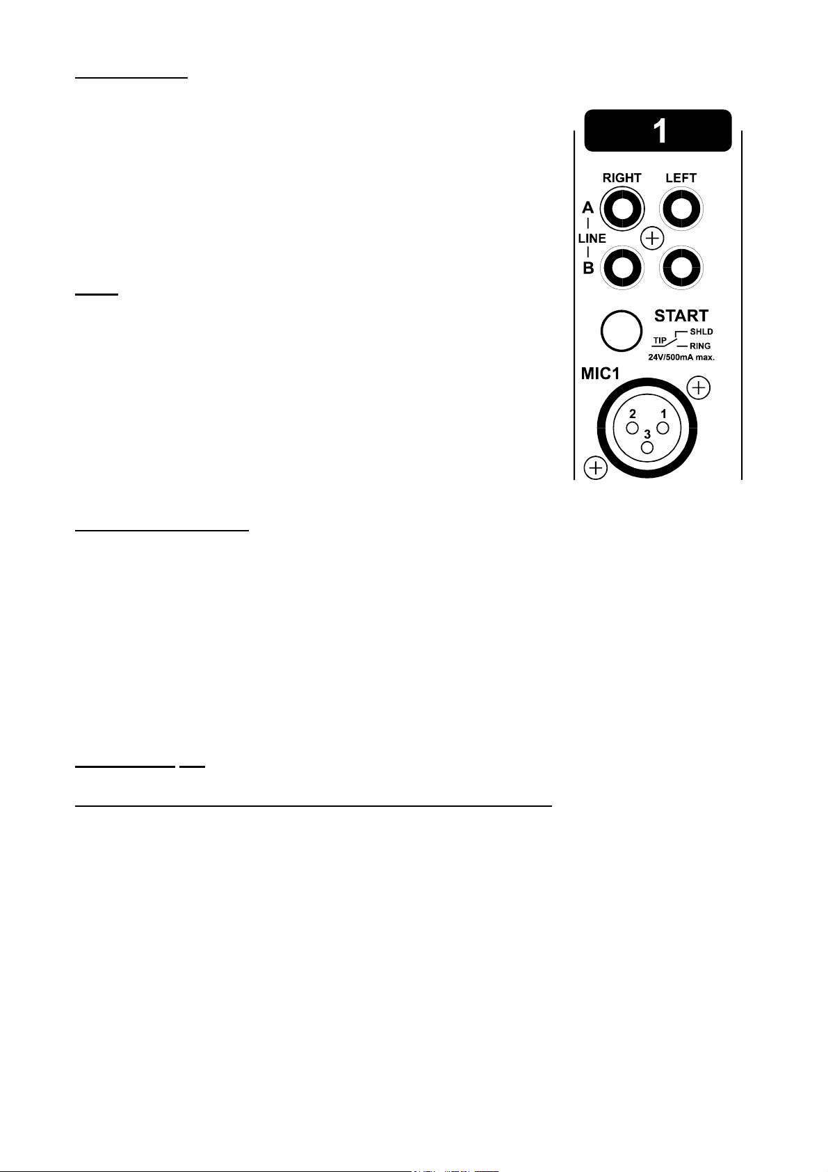
STEREO LINE
The stereo line inputs need to be connected as follows.
The left cinch connector is the left input and the right Cinch
connector is the right input. The shield needs to be connected to the
ground.
The START switch has two active connections to be wired. The tip
and ring are shorted when the ON switch or optional fader switch is
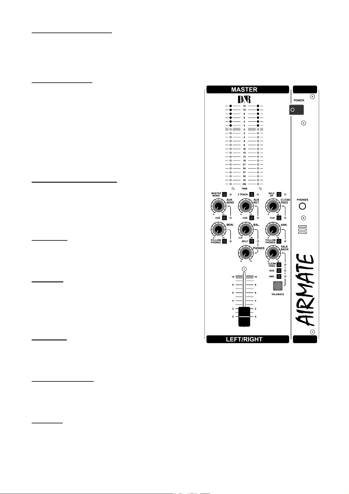
activated. The controls of the input modules have the following
functions.
GAIN
With the gain, the source level is adjusted to the internal mixer level.
The module has a three band equalizer to control the high and low
frequencies individually in bad acoustic environments.
Below the equalizer you will find the stereo CUE switch (Pre Fader
Listening), this switch gives you the possibility to check the signal
before you mix it with your other signals .
The ON switch is used to start turntables and cassette decks as well
as jingle machines. Last control is the 100mm channel fader, this is
the actual control to mix the signals. All channels have long throw
stereo faders.
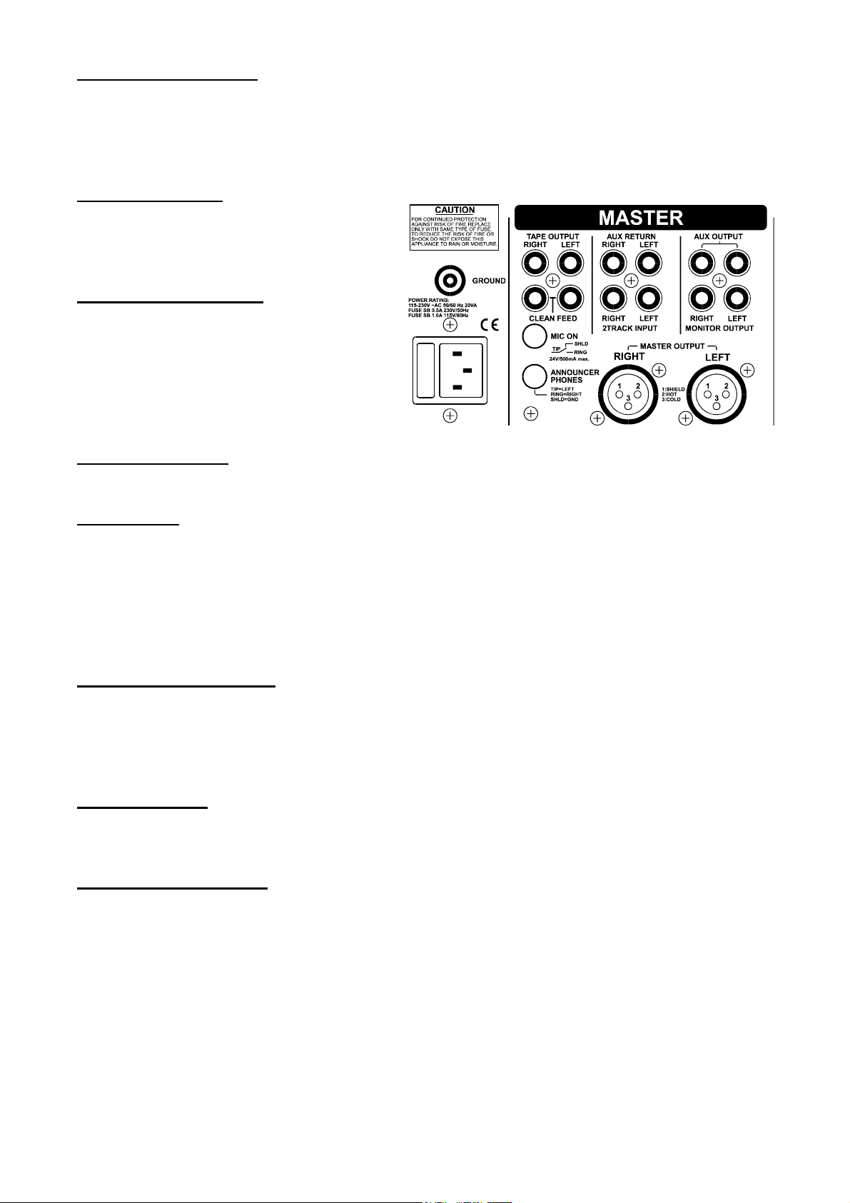
INPUT CONNECTORS
On the back of your Airmate you find six connectors, one has already been discussed, that was
the balanced or symmetrical microphone input, the other two are the stereo line inputs.
On line B you can buy an optional available R.I.A.A. correction amp to be able to mix turn
tables. The level can be set by the gain control to match with every available cartridge.
There is a stereo "CUE " switch on the front to cue the incoming signal. Once you have done
this, you can start the turntable with the ON switch. These switches quick start turntables
through the remote jack by a continuous contact action at the back of the mixer. If your
turntable only needs a puls to start ask your dealer to modify the internal circuitry to change it
into a momentary action, so you can use it as a puls start switch.
*NEVER CONNECT THE MAINS TO THIS REMOTE-JACK*
Connections on the START connector can only be made with a maximum of
24 Volts by 50 mA. Please contact your dealer in case of doubt.
SPECIAL AVAILABLE OPTIONS IN YOUR AIRMATE MIXER
On the input PCB of your Airmate are several jumpers that can be changed to enable different
configurations of the channel settings.
We advice you to have this done by your local dealer if the need arises.
The following jumper settings can be selected:
1. R.I.A.A. correction amp on Jumper J 12 and J 13.
2. Low cut filter on Mic input only through Jumper J 3.
3. 48 volt phantom power via Jumper J 15.
4. Stereo Aux send pre or post selectable via Jumper J6 (post is default).
5. Start jack de-activating by Jumper J 11 (1-2).
6. Monitor Muting active by On switch via Jumper J 11 (3-4) (for broadcast).