D&R Sirius User manual

Sirius Digital On Air Console Manual
V1.0.0.8

Contents
Sirius digital Mixer from D&R Phone +31 294 418014, email: info@d-r.nl Page 2
Dear Customer,
Thank you for choosing the SIRIUS console.
The Sirius is designed by specialists in the field of radio broadcast and intended to be used
as a 24-hour "On-Air" console as well as a production console.
You are not faced with a huge manual because it is simply not necessary because of the
natural recognition of all functions on the user interfaces. All functions are self-
explanatory and you will certainly appreciate the ergonomics of this design. No digital
layering just direct access to all relevant functions, as we think it should be in daily practice
Jan Betten and Anton Prins both equally responsible for the design of the Sirius always
value suggestions from you once you have become familiar with your Sirius.
We will certainly learn from your comments, and we will very much appreciate the effort
and time it will take for you to communicate your idea’s and suggestions.
We are confident that you will be using the Sirius for many years to come, and wish you a
lot of success.
With kind regards,
Duco de Rijk
PRESIDENT
D&R ELECTRONICA WEESP B.V.
Rijnkade 15B
1382 GS WEESP-HOLLAND
The Netherlands
Phone: 0294-418 014
Fax: 0294-416 987
Website: http://www.d-r.nl
E-mail: info@d-r.nl

Contents
Sirius digital Mixer from D&R Phone +31 294 418014, email: info@d-r.nl Page 3
1INTRODUCTION.........................................................................................................................................................5
2WHY IS THE SIRIUS IS A DIGITAL CONSOLE? ................................................................................................6
3SYSTEM PARTS..........................................................................................................................................................7
3.1 THE CONTROL SURFACE ...................................................................................................................................7
3.2 THE IN-OUTPUT RACK .......................................................................................................................................7
3.3 THE CONTROL PROCESSING UNIT AND ITS SOFTWARE ................................................................................7
4AUDIO SIGNAL PATHS ............................................................................................................................................8
4.1 INPUT MATRIX......................................................................................................................................................8
4.2 BUSS STRUCTURE................................................................................................................................................8
4.3 OUTPUT MATRIX .................................................................................................................................................8
5PROCESSING..............................................................................................................................................................9
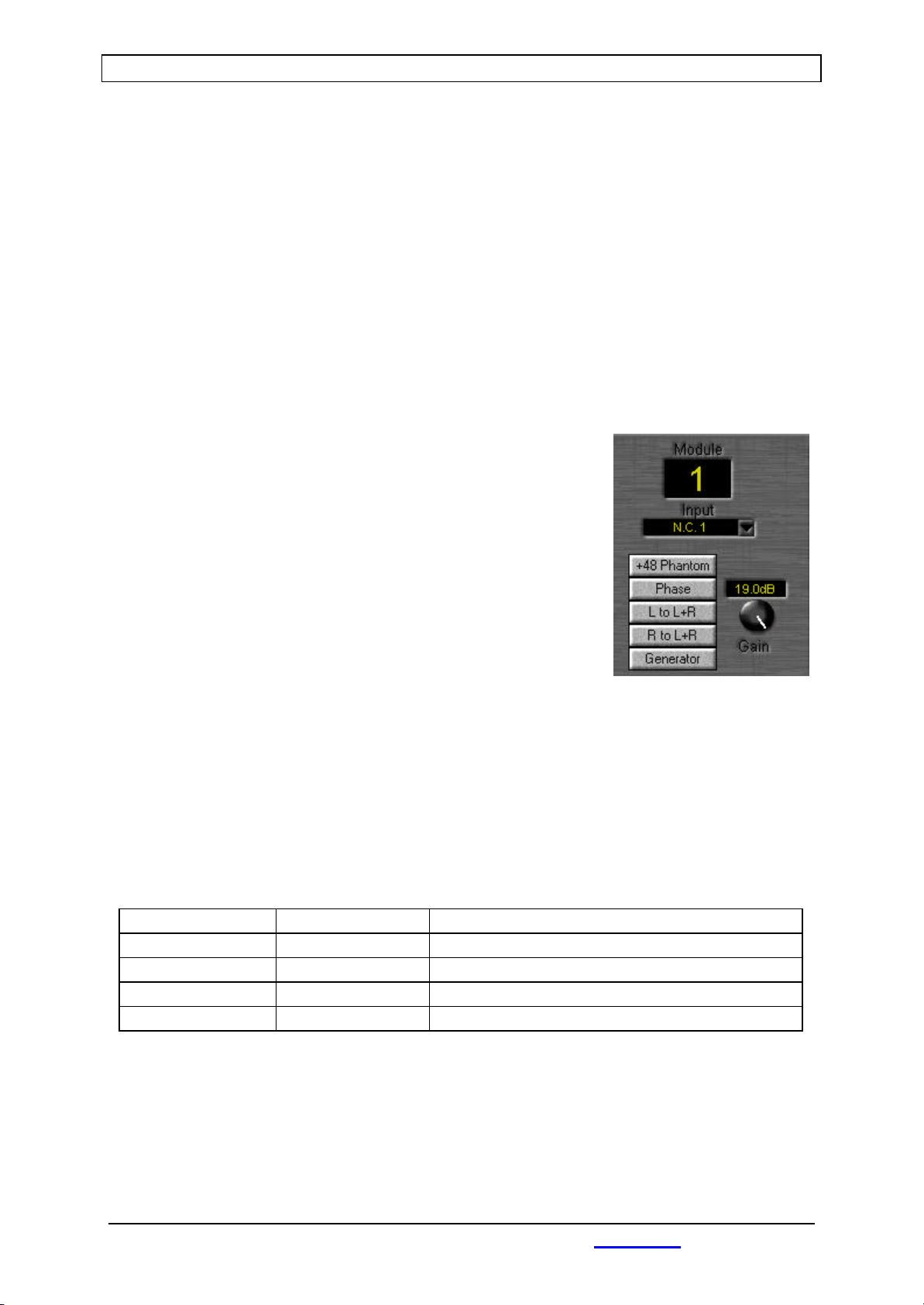
5.1 INPUT PROCESSING AND ROUTING ....................................................................................................................9
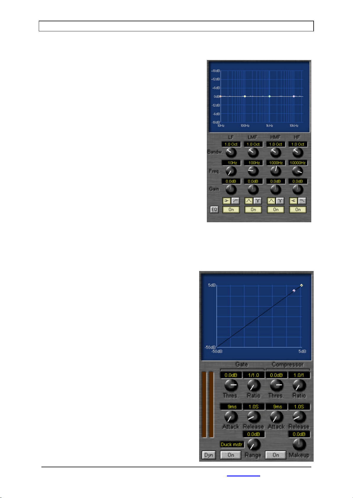
5.2 EQ .......................................................................................................................................................................10
5.3 DYNAMICS ..........................................................................................................................................................10
5.3.1 Gate...............................................................................................................................................................10
5.3.2 Compressor.................................................................................................................................................11
5.4 LEVEL AND ROUTING.......................................................................................................................................11
5.4.1 Aux. busses..................................................................................................................................................11
5.4.2 Program busses..........................................................................................................................................11
5.4.3 Mix busses...................................................................................................................................................11
5.4.4 Cleanfeed busses........................................................................................................................................12
5.4.5 CUE buss.....................................................................................................................................................12
5.4.6 Fader/VCA groups....................................................................................................................................12
5.5 SEND MODULES AND OUTPUT ROUTING.........................................................................................................13
5.6 MASTER AND CRM FUNCTIONALITY..............................................................................................................14
5.6.1 Clock and Timer........................................................................................................................................14
5.6.2 Master functions........................................................................................................................................14
5.6.3 Master meters.............................................................................................................................................15
5.6.4 CRM.............................................................................................................................................................15
5.6.5 Studio...........................................................................................................................................................16
6INTERFACING...........................................................................................................................................................17
6.1 I/O RACK............................................................................................................................................................17
6.1.1 CPU...............................................................................................................................................................17
6.1.2 MUX .............................................................................................................................................................17
6.1.3 Power supply + ON/OFF switch.............................................................................................................19
6.1.4 Digital to digital unit................................................................................................................................19
6.1.5 Analog to digital unit...............................................................................................................................20
6.1.6 Digital to analog output unit..................................................................................................................21
6.2 CONTROL SURFACES........................................................................................................................................22
6.2.1 How do I connect the Control Surfaces?..............................................................................................22
7THE SOFTWARE.......................................................................................................................................................23
7.1 GLOBAL SETTINGS ...........................................................................................................................................24
7.1.1 Clock source...............................................................................................................................................25
7.1.2 Selection......................................................................................................................................................25
7.1.3 Generator.....................................................................................................................................................25
7.1.4 Metering ......................................................................................................................................................25
7.1.5 CUE set-up ..................................................................................................................................................26

Contents
Sirius digital Mixer from D&R Phone +31 294 418014, email: info@d-r.nl Page 4
7.1.6 Audio watchdog.........................................................................................................................................27
7.1.7 Remotes........................................................................................................................................................27
7.1.8 Remote in.....................................................................................................................................................27
7.1.9 Remote out ..................................................................................................................................................27
7.2 INPUT AND OUTPUT SET-UP..............................................................................................................................28
7.2.1 Input set-up .................................................................................................................................................30
7.2.2 Related output............................................................................................................................................30
7.2.3 Input settings..............................................................................................................................................31
7.2.4 Remotes........................................................................................................................................................31
7.2.5 Input active generates:.............................................................................................................................32
7.2.6 Digital to digital input set-up..................................................................................................................33
7.2.7 Analog to digital input set-up.................................................................................................................33
7.2.8 MIC to digital input set-up......................................................................................................................34
7.2.9 Output set-up...............................................................................................................................................34
7.2.10 Related input.........................................................................................................................................34
7.2.11 Output settings......................................................................................................................................34
7.2.12 Remote....................................................................................................................................................35
7.2.13 Output mute controlled by..................................................................................................................35
7.2.14 Digital to digital output set-up..........................................................................................................35
7.2.15 Digital to analog output set-up ........................................................................................................35
7.3 MACRO SWITCH SET-UP...................................................................................................................................36
7.4 USER MANAGEMENT .........................................................................................................................................37
7.4.1 New user.......................................................................................................................................................37
7.4.2 Edit user.......................................................................................................................................................37
7.4.3 Delete user...................................................................................................................................................39
7.5 SNAPSHOTS AND PRE-SETS..............................................................................................................................39
7.5.1 Total snapshots..........................................................................................................................................39
7.5.2 EQ pre-sets..................................................................................................................................................40
7.5.3 Dynamics pre-sets......................................................................................................................................40
7.6 WORK ENVIRONMENT ......................................................................................................................................41
7.7 SERVICE .............................................................................................................................................................42
7.7.1 Control surface...........................................................................................................................................43
7.7.2 19” Rack......................................................................................................................................................43
7.7.3 Update embedded software......................................................................................................................44
8SPECIFICATIONS.....................................................................................................................................................45
9PRODUCT SAFETY..................................................................................................................................................50

Introduction
Sirius digital Mixer from D&R Phone +31 294 418014, email: info@d-r.nl Page 5
1Introduction.
This manual will give you a detailed explanation of all the possibilities of the Sirius.
Itisadvisedtoreadthismanualoncebefore hittingthefirstknoborswitchoreventohookup
the entire system.
I know that that is actually the firsts thing you want to do but please do NOT and discipline
yourself to read the manual first.
The manual gives all sorts of valuable information before starting and it avoids lots of
unanswered questions otherwise addressed to us.
You can use this manual later on as a reference for your questions.
In the first chapters we shall try to give an overview of the Sirius and its features. In this way
you can have an impression of how to implement the system in your application.
The next chapters will deal with interconnecting the various parts of the system and its
external interfacing with your equipment
WhentheSiriusisinstalledandwired,youcanfinalizeitsinterfacingwiththeinstructioninthe
following chapters.
After having installed the Sirius you will have a very complete ON-AIRandproductionmixer
with a human interface that is very intuitive and understandable thanks to its real time
positioned motor-pots.

Why is it the Sirius is a digital console?
Sirius digital Mixer from D&R Phone +31 294 418014, email: info@d-r.nl Page 6
2Why is it the Sirius is a digital console?
Digital audio is slowly accepted as the new standard for audio. The Sirius is a design based on
new generation software for mixing consoles with Digital Signal Processing. The Sirius is
designedusingthelatestavailabletechnologyinitsfieldanditsdesignsimplysurpassesmost
other digital design techniques.
The Sirius accepts all digital audio sources without any loss of quality. Use of sample rate
convertersonallinputssimplyeliminateallproblemsrelatedtodifferentsamplefrequenciesin
older digital desks.
You can virtually connect any of today’s digital and analog sources to the Sirius.
Inthedigital domain there areevenmoreadvantages, such as reproducingandcopyingsignals
without any loss. Patching is also a thing of the past; the built in digital router takes care of
this.
All processed data through the whole system is floating point. It means infinite headroom
throughout the whole system. It means that if you useextensiveEQ-in, the processing could
lead to signal being pushed into the red area of the led-bars and the fader, or even an output
really can compensate it for send control. It’s amazing is not it?
The same goes for an overdriven mix-buss;thiscanbecorrectedbyloweringtheoutputsend
level. Features only available in a modern up to date digital system.
In the digital domain it is possible to implement extra features. Outboard
gates/compressors/limiters are a thing of the past. The Sirius has one in everyinput channel!
More exciting features are that every parameter of an input signal flow can be stored and
retrieved later. You can build a library of snapshots and pre-sets and save them on hard disk
or floppy.
Digital technology shall give you more flexibility and power than ever experienced in the
analog domain. Reliability is built in by using the industrial Windows NT operating system.
Special attention has been given to reliability equally well in hard and software in many areas
of the design.

System structure of the Sirius
Sirius digital Mixer from D&R Phone +31 294 418014, email: info@d-r.nl Page 7
3System Parts
The Sirius is constructed out of a number of components. The control surface, the in-output
racks and the processing power with operational software.
3.1 The Control Surface
The control surface is actually that part of a system that you interface with the most.
The Control Surface is constructed out of different system parts that can be built into studio
furniture.
It is possible to connect a maximum of two fader control units (with up to 32 faders)and a
Super Module to the main processing power unit. Every unit has its own power supply (115
volts or 230 volts) and a sub-D connector for interfacing with the In-Output (I/O) rack.
3.2 The in-output rack
This rack can be mounted in a rack system accepting 19” rack system parts. It can accept
variousI/Ounitsalltoyourownindividualneeds.Therackmountableunitsaretakingcareof
all in-output signals as well as all remote interfacing.
The main CPU that controls the entire mixer shall also be a part of this rack.
We shall discuss this in one of the next chapters in detail.
The I/O rack (including processing unit) has two power supply connectors (115V of 230V) and
three connectors (9 pin SUB-D) for interfacing with the control surfaces.
3.3 The Control Processing Unit and its software
Thisistheengine of the Sirius. It is herethat all (audio) datais processed. Due tothe fact that
the Sirius is software based, all functions can be checked in real time. All i/o’s can be routed,
inputs can be labeled, equalizers set, etc.
We will extensively explain how this works in detail in the following sections of this manual.

audiopath in the Sirius
Sirius digital Mixer from D&R Phone +31 294 418014, email: info@d-r.nl Page 8
4Audio Signal Path
TheSiriusisadigitalOn-Airmixerwithincredibleflexibility.Itisthereforeanecessitytofully
understand its potentials and we will try to give you a clear picture of all the features of this
mixer.
It is possible to connect a total of 64 inputs and 64 outputs to this mixer. As is standard
practice in professional digital audio, there is no direct physical connection to the input
modules on your control surface.
It is therefore advisable to clearly label all cables connected to the I/O units to avoid
misunderstanding.
4.1 Input matrix
The Sirius gives you the possibility to route any or all of the 64 in-and outputs to any in or
output of the control surface.
The Sirius offers you a 64 to 32 input router to interface the audio with 32 input channels.
A second Matrix, the CRM input matrix is a router of all 64 inputs plus all busses to 6 stereo
monitoringinputs.Thisgivesyouthepossibilitytolistenonyour CRM to a selection of inputs
and /or busses (for instance Prog. 1 and an On-Air signal).
A similar matrix is used for the studio buss.
4.2 Buss structure
The processed 32 audio signals can be routed to different busses.
Busses that are available are;
•2 stereo program busses
•3 stereo aux. busses
•8 mono/4 stereo mix-busses
•8 mono/4 stereo cleanfeed busses
•Stereo CUE buss
The 6 CRM sources (selected from the CRM input matrix) are summed into the CRM buss.
The6Studiosources(selectedfromtheStudioinput matrix)aresummedintotheStudiobuss.
4.3 Output matrix
All busses of the Sirius can be routed via an output matrix of 32 to 64 to a selected output.
It is also possible to connect more than one output to the same buss.

Processing
Sirius digital Mixer from D&R Phone +31 294 418014, email: info@d-r.nl Page 9
5Processing
It is possible to process 32 channels in parallel. Every channel processing handles input, EQ,
dynamics and level.
Optional there is a Send module that behaves like an output router.
Now we will give you a global view of the power of the Sirius digital mixer. All hands on
possibilities described here can be found on the main screen of the system. Just like any
analog system.
5.1 Input processing and routing
The input signal can be processed as soon as it is converted into
thedigitaldomain.Butbeforeyouareabletoactually change the
input signal it has to be assigned to a specific input module.
Youcanassignaninputsignaltoamodulebyclickingontheinput
area labeled N.C. (Not Connected).
Having done this you are presented with a list of all available
inputs to choose from. It is here that you decide which input
source is connected to which input module. This is a matrix type
of input selection that is very convenient and sources can be
selected in any sequence just the way you want it to be. These
settings can be saved for recall at any time.
When you are ready with selecting the input sources you need for the job, you can now trim
yourinputlevelwitharangeof40dB(-20dBto+20dB)bywayoftheinputgainpotentiometer.
This can be done on screen or on the gain motor potentiometer in the Super module, as is the
case with the phase reverse switch.
Youcanassign a stereo source toamoduleinthe same way. The softwarerecognizesthatyou
are assigning a stereo signal and subsequently connect these signals in stereo to a module.
The chart below here shows you all possibilities when dealing with mono or stereo signals.
‘L to L+R’-knob ‘R to L+R’-knob Function
Off Off Stereo
On Off Left to left and right
Off On Right to left and right
On On Mono
Thelowestknobactivatesthegenerator. Thisfunctionoverrides allotherinputselectionsand
provides you with your own selection of test signals. These selections are made in the Global
settings chapter that is discussed in one of the next chapters. For now it is good to know that
you can select out of Pink Noise, White Noise and a Sine wave.

Processing
Sirius digital Mixer from D&R Phone +31 294 418014, email: info@d-r.nl Page 10
5.2 EQ
The Sirius has a full four band parametric Equalizer.
The LF band can be used as a low shelving band or as a
“low cut” filter.
The LMF en HMF bands can be used in a “bell” or
“notch” mode.
The HF Band can be used as a high shelving equalizer
or “high cut” filter
All bands have adjustable level, frequency, and
bandwidth with absolute values written in real time on
your screen.
Each band can individually be switchedon or off.
An overall EQ on/off switch overrides all individual
on/off EQ switches.
All settings can be done in real time on the Super module by rotating the pots there. Or it can
bedonebywayofaMousemovement(themotor-pots will follow) or in caseof loading settings
from memory all motor-pots in the Super Module will instantly go to the memory position of
the saved EQ setting.
5.3 Dynamics
Everychannelhasa dynamicssection withagateand
a compressor. Dynamics can be switched on or off as
a “pair”, but also individually a gate can be switched
off or the compressor.
5.3.1 Gate
Gate parameters are Threshold, Ratio, Attack,
Release and Range.
The Threshold adjusts the level the gate opens.
When an input signal is higher than this pre-set level
the gate will open. The Attack controls the speed in
which the gate opens. The Ratio control can be used
to create a downward expander. The 1/20 position
creates a 100% gate function

Processing
Sirius digital Mixer from D&R Phone +31 294 418014, email: info@d-r.nl Page 11
The Attack controls the speed in which the gate opens.
The Release determines the time it takes before the gate closes again.
The Range control adjusts the amount of attenuation when the gate is closed
An On/Off switch is implemented.
5.3.2 Compressor
ThecompressorcanbeadjustedwiththeThreshold,Ratio,Attack,ReleaseandMake-upgain
controls.
The Threshold setting controls the moment the compressor starts working.
The Ratio controls the in/output relationship when compression takes place. A maximum of
20:1 is equivalent to a limit function.
The Attack control adjusts the time it takes to respond to an increase of input signal.
The Release control adjusts the time it takes to recover from compression.
The make-up gain can adjust the lost gain when heavy compression takes place.
An overall On/Off switch is silently switching the compressor on or off.
5.4 Level and Routing
When the signal has been processed in level and dynamics it can be routed to one or more
outputbussessuchastheAux.busses,Program(main)busses,Mixbusses,Clean-feedbusses
and the stereo CUE buss. A description of individual output busses is written below.
5.4.1 Aux. busses
The Sirius has three stereo AUX busses. These busses accept
signals from the input module pre or post fader, depending upon
your choice.
Every Aux send can be adjusted in level and in left/right balance.
A Mute function in the form of an ON switch is available.
5.4.2 Program busses
TheSirius hastwoprogram bussesimplemented.These areaccessiblethrough Program1and
or 2. This signal is post fader of course.
5.4.3 Mix busses

Processing
Sirius digital Mixer from D&R Phone +31 294 418014, email: info@d-r.nl Page 12
When more outputs are required an extra 8 output busses are available for addressing signal
to. These busses can be assigned to pre or post fader.
A choice can be made to use these busses as 8 mono output busses or as 4 stereo output
busses.
This choice will be made with the mono switch. When the output
busses are set to be stereo busses the balance control on the input
modules will behave as expected. In case the output busses are
mono, the balance control will not be active. The next step is to
assign the busses.
5.4.4 Clean-feed busses
The Clean-feed busses are very similar to the mix busses with the
only exception that you can switch off a Clean-feed buss avoiding
signal to be send to that buss from a specific channel.
The adjustments for mono/pre/post fader are identical to the mix-
buss programming.
5.4.5 CUE buss
The stereo CUE buss can be fed from an input signal pre fader by
way of the Cue switch.
An alternative function of the CUE buss is to use it as a talkback
communication switch. We will explain this later.
5.4.6 Fader groups
Positioned left of the fader section you see the fader-group switches. These can be used to
create fader-groups. There are four fader-groups implemented.
WhenyouassigntheGroupMaster(Grp-Mstr)thechannelbecomesthemasterofthegroup.
The next step is to select of what group this becomes the master by assigning Group 1 to 4 to
this master. There is of course only one master for each group.
The slave faders will not move (by its motors) being in the group to give you the possibility to
continuouslymonitor theslavebalance. Individual“slave”balancing willalwaysbepossiblein
a group.

Processing
Sirius digital Mixer from D&R Phone +31 294 418014, email: info@d-r.nl Page 13
5.5 Send modules and output routing
When you have assigned a signal to several busses no audio is to be
heard yet until you have decided which outputs you are goingtousefor
these assigned signals.
In the send module you can select which audio Source you want to use,
forinstance “Prog.1”(youcanmakeaselectionfromalloutputbusses,
these busses are considered to be stereo)
Further you have the possibilitytoadjustthelevelofthetotalbusswith
the knob in the software, or the hardware motor-pot on the send
modules in your frame.
To have a fixed level on your buss-outputs (eg. for Prog.1) you have the
button ‘0dB fixed’. This Button doesn’t set the hardware knob, but
disables it and make’s the audio path unity gain.
The Mono switch makes the buss mono (summing left and right audio).
The CUE button on the send panels gives you the ability to listen to the
audio signal present on these busses.
Inthe“Destination”sectionyou can selectwhichoutput can beusedfor
the selected buss. This type of output matrix/router provides you with
nearly unlimited possibilities for your routing needs. The associated
mute function kills the sound on this dedicated output.
With the ‘L to output’ and ‘R to output’ buttons you are able to use the
busses as mono channels. Below you can see the results of different settings:
‘L to L+R’-knob ‘R to L+R’-knob Function
Off Off Stereo
On Off Left to left and right
Off On Right to left and right
On On Not possible
NOTE:
Toavoidany level problem it is possibletofixtheoutput level to 0dB. Theassociatedlevelpot
becomes inactive then. You are certain now that the output buss level is exactly the same as
the audio level on the buss.

Processing
Sirius digital Mixer from D&R Phone +31 294 418014, email: info@d-r.nl Page 14
5.6 Master and CRM functionality
This broadcast mixer has extensive monitoring and master features. You have a Clock, a
Timer, On-Air indication, assignable meters and CRM source selection. This all is located in
the upper section of the display as shown below.
5.6.1 Clock and Timer
Situated left in this master section
you see an analog type clock
producing the actual time. The
nextsectionhousestheTimerand
its controls. The Timer is accurate
down to 1/10 of a second. You can
start the Timer by clicking the
Start button or by assigning the Timer to a fader-start (see 7.2 Input and output )
The Stop knob stops the Timer when started by the Start knob or fader-start.
The Reset button shall reset the Timer to 00:00:00:00
5.6.2 Master functions
In the master section you will also find the red light signaling. This is located below the Clock
itselfonthescreen.Whenachannelisactivatedandyouhavelabeledthischannel to generate
red light (see 7.2 Input and output ) only then ‘On-Air’ light shall be activated.
NOTE:
Red light signaling is active for both Red-light1andRed-light 2 busses, however both busses
can be assigned individually to the remotes of course.
Below the Timer you see three knobs: CUE Reset, Conference talk-back and Panic. These
knobs have the following functions.
CUE Reset Resets all active Cues.
Conference Talk-back When this knob is activated your CRM mic will be added to the CUE
buss.Alloutputs,selectedaspartofthe‘ConferenceTalk-back’
(see 7.2 Input and output ) shall be switched to the CUE buss to
be able to listen to the CRM Mic.
Panic This function shall provide you with the default setting to be
loaded instantly when necessary. In this way you always get a
known setting back in your console when you are lost in
programming.

Processing
Sirius digital Mixer from D&R Phone +31 294 418014, email: info@d-r.nl Page 15
5.6.3 Master meters
In the middle section are the master meters.
These meters shall always present the signal
that is assigned to the selected output buss.
Byclickingonthenameofthemeterapop-up
menu appears.Here youcan select the signal
that the meters are displaying. Selection can
be made from all busses.
5.6.4 CRM
The far right area is the CRM
section. This section determines
what you are going to hear in your
Control Room Monitors.
You can select out of 6 stereo
sources that are labeled left from
the CRM pot.
Byclickingonthelabel(blackarea)apop-upmenuappearswithalltheinputsandbusses.Itis
up to you how many two tracks you want directly accessible on your CRM here by activating
any input available.
The next step is to select which source you want to listen to. These knobs can function in two
ways. Either additive or alternating, a decision made in the ‘Global Settings’ (see 7.1.2
Selection).
Of course you have the possibility to adjust the level, dimming and muting on the CRM buss,
these knobs are located in the same area.
The dim function on the CRM is a maximum level setting. Meaning that the level adjusted by
theup/downswitchesis the maximumlevelwhen dimisactive.In thiswayyoucan tunethedim
to an acceptable level (without feedback) and if the level is lower, the dim will not adjust the
level or else it will be adjusted to the dim level.
As an extra feature it is also possible to switch the right CRM signal out of phase. It is a
technique to check if all signals are in phase without interrupting live signals.

Processing
Sirius digital Mixer from D&R Phone +31 294 418014, email: info@d-r.nl Page 16
5.6.5 Studio
Youcanselectoutof6stereosourcesthatcanbeelectronicallylabeledandarelocatedleft of
the CRM pot.
By clicking on the label (None) a pop-up menu appears with all the inputs and busses. It is up
to you how many two tracks you want directly accessible on your Studio output here by
activating any input available.
The next step is to select which source you want to listen to. These knobs can function in two
ways. Either additive or alternating, a decision made in the ‘Global Settings’ (see 7.1.2
Selection).
Follow CRM shall connect the CRM to the studio buss.
NOTE: The Studio selection becomes inactive then.

Interfacing
Sirius digital Mixer from D&R Phone +31 294 418014, email: info@d-r.nl Page 17
6Interfacing
Due to the flexibility of the Sirius all interfacing will be dealt with in separate sections.
All the different I/O units shall be discussed here.
6.1 I/O rack
The I/O rack can be selected out of several interface units to satisfy individual needs in this
matter.
Some of the units have to be part of the rack as essentials. These are the CPU, the MUX and
the power-supply.
All other components can be selected based upon necessity. We are talking about ‘Digital to
Digital units’, ‘Analog to Digital units’ and the ‘Digital to Analog unit’.
6.1.1 CPU
The CPU is used to manage the whole system. Via this CPU you can control the complete
mixing console.
All you need is a mouse, a keyboard and a monitor. These items can be connected to the back
of the unit on standard industry connectors.
Furthermore there is a large 68-pole connector (SCSI ‘twisted pair’ connector) on the back
that needs to be hooked up to the MUX card. The maximum length tested is 1.8 meters. We
suggest to have de CPU and I/O rack located together.
The 115V or 230V power connector should only be connected when the whole system is wired
completely.
6.1.2 MUX
The MUX unit takes care ofcollecting all data in the system. It is therefore that you will notice
lots of cables. For you as end user only the necessary cables for performing its normal duties
are accessible.
The LED’s positioned on the left side indicate the status of the MUX unit:
Power the MUX unit is powered.
OK indicates that the software is running properly.

Interfacing
Sirius digital Mixer from D&R Phone +31 294 418014, email: info@d-r.nl Page 18
AES3 Error indicates a missing AES3 synchronisation.
On the far left of the MUX unit there are 4 remote connectors (SUB-D 9 pole).
On every connector there are 2 remote inputs and 2 remote outputs.
A wiring table below shows the actual pinning of the 9 pin Sub-D connectors.
Pin # Pin function
1 Common Contact 1 (CC)
2 Normally Closed 1 (NC)
3 Normally Open 2 (NO)
4 Remote 1 in (0/5V)
5 GND
6 Normally Open 1 (NO)
7 Common Contact 2 (CC)
8 Normally Closed 2 (NC)
9 Remote 2 in (0/5V)
In the area labeled “Clock” you see various connectors to drive external clock signals and
connectors to accept different synchronization clocks for external equipment.
The software allows for selecting different synchronization sources. The MUX unit accepts
external sources with sample-rates from 20kHz up to 49kHz.
AES3 In is used to synchronize the Sirius internally.
AES3 Out On this connector the internal frequency is offered on AES3 format to
synchronize external equipment.
MC In This is the master clock input. The Master-clock is 256 times the internal
sample frequency.
MC Out The Master-clock output always produces the internally used master clock
frequency.
FC In The Frame-clock in connector (also known as “Word clock”). This input can
also be used to synchronize equipment.
FC Out This connector always delivers the internal Frame-clock.
OntheMUXunittherealsoallconnectorsforthecontrolsurfaces(Controlsurfaces1,2,3). It
does not matter which Control Surface Unit (CSU) unit is connected to which CSU connector.
However it is useful to consider that the system starts counting (modules) from theconnector
with the lowest number.
You can extend the SUB-D9 cable to a maximum length of 50 meters. That makes it possible
to have your 19 “Rack located in a machine room
Note: remember that your Keyboard/Monitor/Mouse connections must be extended as well.

Interfacing
Sirius digital Mixer from D&R Phone +31 294 418014, email: info@d-r.nl Page 19
A 68-pole connector (to interface with the CPU) is also to be found on this unit.
6.1.3 Power supply + ON/OFF switch
TheinternalPower supply shows thepowersupplycordconnector for accepting 115voltor230
volts 50/60Hz.
All other units are internally connected with this unit.
6.1.4 Digital to digital unit
Thedigitalinputandoutputunitprovidesyouwiththeabilitytoreadseveraldifferenttypesof
digital signals. The software allows you to choose from SPDif (Coax), Optical or AES/EBU
inputs and outputs. All outputs are giving an identical signal; so interfacing should not be a
problem.
Tomake life easier the Sirius hassample rate converters onall inputs. It istherefore possible
toconnectsignalswithdifferentsampleratesorevenasynchronousondifferentinputchannels
without facing any synchronization problems. The frequency range that can be dealt with can
be anything between 20kHz up to 100kHz.
The LED’s on the left side are indicating the status of the DD-unit:
Power indicates power is present.
OK indicates software is running.
Thedigitalunithasfouridenticalsectionsofferingtwoinputchannelsandtwooutputchannels.
On the top left you find the Coax input and the Coax output connector.
Beneath these two coax connectors you see two XLR connectors for interfacing with the
AES/EBU (AES3 standard). To the right you will find the optical S/PDIF interface.
The LED’s in these units indicate the status of the digital input:
Error indicates whether synchronization is present on the digital input.
Active indicates whether the input is in active.

Interfacing
Sirius digital Mixer from D&R Phone +31 294 418014, email: info@d-r.nl Page 20
Every section also provides for a remote connector with two inputs and two outputs. When
input is assigned to a module the corresponding remotes will perform the remote functions.
An overview of the entire pin functions:
Pin # Pin function
1 CC1
2 NC1
3 NO2
4 remote 1 in (0/5 Volt)
5 GND
6 NO1
7 CC2
8 NC2
9 remote 2 in (0/5 Volt)
6.1.5 Analog to digital unit.
Theanalogtodigitalinputunitprovidesyouwithelectronicstoconverttheanaloginputsignals
in very high quality into the digital domain with the proper sample frequency.
The LED’s positioned far left indicate status of the AD-unit:
Power indicates power is present
OK indicates software is running.
The unit has four identical sections each reading two channels. The analog audio can be
presented via XLR connectors in left right pairs.
The LED’s in these units indicate the status of the digital input:
Active indicates whether the input is in actual use.
Table of contents
Other D&R Music Mixer manuals