Dantel 46033 User manual

CAUTION
•Install or remove modules from the shelf only when the power is off.
If you install a module in the shelf with the power on, the internal
circuitry may suffer damage and the product warranty will be void.
•Remove and install circuit boards only in a static-safe environment
(use antistatic wrist straps, smocks, footwear, etc.).
•Keep circuit boards in their antistatic bags when they are not in use.
•Do not ship or store circuit boards near strong electrostatic, electromag-
netic, magnetic, or radioactive fields.
•For more complete information on electrostatic discharge safety
precautions, refer to BellcoreTM Technical Reference # TR-NWT-000870.
Copyright 1998 by Dantel, Inc. • Dantel is a registered trademark of Dantel, Inc. • ISO 9001 Registered
Printed in the U.S.A.
INSTALLATION & OPERATION MANUAL
46033-1098 <90-00011>
46033
E-SYSTEM ADAPTER
About this Practice:
This practice has been reissued to:
• Update
Ordering Information
section.
• Add note to
General Description
section on the difference between
a -01 and a -02.
Issue date: October 1998
Reissued Practices: Updated and
new content can be identified by a
banner in the right margin.
UPDATED
Table of Contents
Ordering Information ........................................................................... 2
General Description.............................................................................. 2
Circuit Description ............................................................................... 3
Installation............................................................................................ 5
Operation ............................................................................................ 11
46033-01 Switch Settings ................................................................... 12
Technical Specifications ..................................................................... 46
Warranty ............................................................................................. 48
DATA
XMT
A1146033-00 REV__
46033-XX
E-SYS
ADAPTER
CARRIER TEST
XMT
RCV
NORMAL

PAGE 2 46033-1098 <90-00011>
ORDERING INFORMATION
NOTE: This section lists the different options available for this product. To order any of the avail-
able options, contact Dantel Inside Sales through our toll-free number, 1-800-432-6835.
OPTION NUMBER FEATURES
B11-46033-01 E-System Adapter (Interfaces TASC, SCOTS, TCAS, NMA)
A11-46033-02 E-System Adapter (Interfaces NMA)
B11-46033-11 E-System Adapter (Interfaces SCC)
GENERAL DESCRIPTION
The 46033 E-System Adapter module provides an interface
between Dantel’s 460 Alarm and Control System (460 ACS)
and the following alarm centers:
NMA Network Management and Analysis
TASC Telemetry Alarm Surveillance Center
SCOTS Surveillance and Control of Transmission Systems
TCAS T-Carrier Administration System
SCC Switching Control Center
To the alarm system, the 460 ACS appears like an E2, E2A, or
E2AA alarm remote.
The 46033 is available in three options. Refer to the Ordering
Information section.
Each 46033 has a capacity of two E-System addresses, but they
must be consecutive. Each address represents 64 displays of
alarm information received from two 46020 Multiple Alarm
Processor (MAPs) or a total of 128 displays (four MAPs) for both
addresses. Each display represents 64 alarm points.
-01, -02 Options
7680 points (the first four displays of each address are used for
new and existing alarms)
NOTE: The difference between the -01 and the -02 is in how it reports
MAP failures. If a 46033-01 is configured (with switches) to
poll a MAP that does not exist, a device failure is not reported
to the Alarm Center.
Conversely; if a 46033-02 is configured (with switches) to poll a
MAP that does not exist, a device failure is reported to the
Alarm Center.
Both options will report a device failure to the Alarm Center if
an in-service MAP fails.
UPDATED
UPDATED

46033-1098 <90-00011> PAGE 3
GENERAL DESCRIPTION
CIRCUIT DESCRIPTION
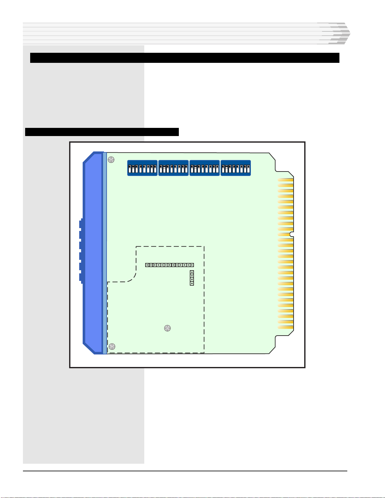
The 46033 E-System Adapter functional schematic is shown
in Fig. 1.
CPU (Central Processing Unit)
The major component of the 46033 is its on-board 8-bit micropro-
cessor (CPU). The CPU controls all functions of the module
except for the start-up routine and functional programming.
When power is applied to the module, the CPU reads the
EPROMs to set itself for the appropriate logic functions it is to
perform.
The CPU translates data between the two different system
protocols to interface the 46020 Multiple Alarm Processor of the
460 ACS to standard E-Systems. A secondary data bus output
from the CPU drives a green LED labeled DATA XMT that
lights when the unit is transmitting data to the E-System.
Data Control
For data input/output, the module has an Asynchronous Com-
munications Interface Adapter (ACIA) that bi-directionally
controls data to be handled by the CPU. When the unit receives
a block of data that constitutes a command or routine request,
the ACIA sequences the data to the CPU using random access
memory (RAM) as a buffer to temporarily store the data. When
the CPU goes idle, the ACIA activates and dumps the next data
block from the RAM to the CPU for translation and output.
Logic Functions
The logic functions of the 46033 accomplish the task of data
protocol translation and conversion. The Erasable/Program-
mable Read-Only Memory (EPROMs/Firmware) on its circuit
board provide nonvolatile memory to configure the CPU at
startup and program it for the appropriate logic functions. The
-11 Option
16 points (normally, the first subgroup of group four)
The 46033 is a plug-in PC board module that fits into any
400-type or similar equipment housing. The front panel has an
indicating LED, a subassembly cutout, a carrier test switch, and
jacks. The 46033 is also equipped to accept subassemblies for
data communications.

PAGE 4 46033-1098 <90-00011>
firmware on the associated Multiple Alarm Processor (MAP)
controls the way the 46033 functions. You can change the way
the MAP’s CPU works by changing the firmware.
The option switches configure the CPU and EPROMs for differ-
ent applications by either grounding or inverting the logic levels
at various pins. Configuration (mode of operation) switch set-
tings are listed in a separate publication, 46033 E-System
Adapter Switch Settings, shipped with each unit.
Power Supply
The module power supply provides regulated operating current
and voltage sources for all of the 46033’s circuits as well as for
an optional data communications subassembly mounted on the
module.
FIG. 1 - FUNCTIONAL SCHEMATIC, 46033
CIRCUIT DESCRIPTION
19
EPROM
(FIRM
WARE)
35 -21 TO -56 VDC
17 GROUND
OPTION
SWITCHES
CPU
SUBASSEMBLY
MOUNTING
RECEIVE DATA
OPTION
SWITCHES
TEST
JACKS
POWER
SUPPLY
45 47 49
+5 +12 -12
16
15
21
20
22
RING
CF
CA
TIP
RING
TIP
-
+
-
+
XMT
*
* PINS 16 (CF) &
15 (CA) ARE
FUNCTIONAL
ONLY IF AN
RS232 (49009)
SUBASSEMBLY
IS USED
13
9
RXD
TXD
11
TRANSMIT DATA
REQUEST
TO
SEND
(NOT USED WITH MAP)
ACIA
REGULATED DC OUTPUTS
TO
MAP
(RS232)
RCV

46033-1098 <90-00011> PAGE 5
INSTALLATION
Installation consists of mounting the communications subas-
sembly, setting the switches, installing the module in the
shelf, and checkout.
SUBASSEMBLY MOUNTING
If a subassembly is not installed already, follow the steps below.
Refer to Fig. 3 for the location of the subassembly.
1. Remove the hole plug from the front panel of the module.
2. Remove the three screws from the subassembly standoffs.
3. Place the subassembly on the board.
a. Insert P4 into J4 and P5 into J5.
b. Make sure each connector pin goes straight into its socket.
c. Make sure the subassembly fits closely on the standoffs.
d. Make sure the panel is straight in the opening.
4. Replace the three screws in the standoffs.
5. If you install a 49008, 49013, or a 49029 subassembly, place the
option straps as required for proper operation. Refer to the subas-
sembly manual for strapping information.
Fig. 2 shows the maximum allowable cable lengths for some
common interfaces.
FIG. 2 - RECOMMENDED CABLE LENGTHS
40
RS232
RS422 BALANCED
RS423 UNBALANCED
100 1 10K 100K 1M 10M
10K
4K
1K
100
50
10
CABLE LENGTH (FEET)
DATA MODULATION RATE (BAUDS)

PAGE 6 46033-1098 <90-00011>
SWITCH SETTINGS
The 46033 provides four 8-lever DIP switches that define how
the module operates. Set the switches before installing the
module into the equipment shelf.
For specific switch settings, refer to Tables A and B and the
46033-01 or 46033-11 switch setting publications.
FIG. 3 - SWITCH LOCATIONS, 46033 E-SYSTEM ADAPTER
113
1
4
J5
J4
SUBASSEMBLY
MOUNTING
AREA
12345678 12345678 12345678 ON
OFF
S1 S2 S3 S4
12345678
INSTALLATION

46033-1098 <90-00011> PAGE 7
TABLE A - 46033 E-SYSTEM ADAPTER SWITCH SETTINGS
INSTALLATION
Configuration Number for Second
Address (-01 only). Not used with -02
or -11 options.
Refer to 46033-01 Switch Settings section for S4-2 through
S4-8.
FUNCTION
Second Address ON
Second Address OFF
Configuration Switches (-11 only)
SCC Mode
DMS-10 Mode
DMS-100 Mode
S3-1
ON
OFF
S3-2
OFF
ON
OFF
S3-3
OFF
OFF
ON
S3-4
OFF
OFF
OFF
S3-5
OFF
OFF
OFF
S3-6
OFF
OFF
OFF
S3-7
OFF
OFF
OFF
S3-8
OFF
OFF
OFF
Configuration Number for First Address
(-01 only). Not used with -02 option. Refer to 46033-01 Switch Settings section for S3-2 through
S3-8.
FUNCTION
1200 Baud DCP Polling Rate
9600 Baud DCP Polling Rate
S4-1
ON
OFF
S4-2 S4-3 S4-4 S4-5 S4-6 S4-7 S4-8
FUNCTION
Not Used
MAP 4 Polling ON
MAP 4 Polling OFF
MAP 3 Polling ON
MAP 3 Polling OFF
MAP 2 Polling ON
MAP 2 Polling OFF
MAP 1 Polling ON
MAP 1 Polling OFF
E2A Format
E2 Format
Delay Setting
-01 and -02 Options *
-11 Option
Delay Enabled
Delay Disabled
E-Telemetry Data Rate 600 Baud
E-Telemetry Data Rate 1200 Baud
S1-1
OFF S1-2
ON
OFF
S1-3
ON
OFF
S1-4
ON
OFF
S1-5
ON
OFF
S1-6
ON
OFF
S1-7
ON
ON
OFF
S1-8
ON
OFF
* NOTE: If a higher than normal error rate occurs, or if problems are experienced with the system,
place S1-7 in the OFF position (-01 and -02 options). The -11 option has an automatic delay.
FUNCTION
Address 1 through 256 S2-1 THROUGH S2-8
Refer to Table B. Set for the first address (the second
address is automatically the next number). NOTE: For
customers using addresses starting with 0, subtract 1.

PAGE 8 46033-1098 <90-00011>
TABLE B - S2 SWITCH SETTINGS
114 244
115 245
11690
11791
OFF
ON
1
2
3
4
5
6
7
8
9
10
11
12
13
27
28
29
53
54
8
105 235
106 236
107 237
108 238
109 239
110 240
111 241
112 242
113 243
8
101 127
102 128
103
104
14 92 118
93 119
94 120
95 121
96 122
97 123
98 124
99 125
100 126
246
247
129
130
15
16
17
18
19
20
21
22
23
24
25
26
34
35
36
37
38
39
30
31
32
33
44
43
42
41
40
49
48
47
46
45
51
52
50
62
64
65
63
61
60
59
58
57
56
55
67
66
70
68
69
75
71
72
73
74
78
76
77
80
79
83
84
81
82
88
89
85
86
87
209
210
211
212
213
134
135
131
132
133
161
160
159
158
157 183
184
185
186
187
214
215
216190
217191
192 218
193 219
136
137
138
139
141
140
162
164
165
163
167
166
188
189
201 227
202 228
194 220
195 221
196 222
197 223
198 224
199 225
200 226
144
143
142
149
148
147
146
145
150
170
168
169
175
171
172
173
174
176
203
204
229
230
151
152 178
177
153
154
205
206
207
208156
155
180
179
181
182 234
231
232
233
249
248
250
251
252
253
254
255
12345678
12345678
12345678
12345678
12345678
12345678
12345678
12345678
12345678123456781234567812345678 12345678 12345678
12345678123456781234567812345678 12345678 12345678
12345678123456781234567812345678 12345678 1234567
12345678123456781234567812345678 1234567 12345678
12345678
12345678123456781234567812345678 12345678 12345678
12345678 12345678
12345678
12345678
12345678
12345678
12345678 12345678
12345678
12345678
12345678
1234567812345678123456781234567812345678
12345678 12345678 12345678 12345678 12345678
12345678
12345678 12345678
12345678
12345678 12345678
12345678
12345678 12345678
12345678
12345678 12345678
12345678 12345678
12345678
12345678 12345678
12345678
12345678
12345678
12345678 12345678
12345678
12345678 12345678
12345678
12345678
12345678
12345678
12345678
12345678
12345678
12345678
12345678
12345678
12345678
12345678
12345678
12345678
12345678 12345678
12345678
12345678 12345678
12345678
12345678
12345678 12345678
12345678
12345678
12345678
12345678
12345678
12345678
12345678
12345678
12345678 12345678
12345678 12345678
12345678
12345678
12345678
12345678
12345678
1234567812345678 12345678 12345678
1234567812345678 12345678 12345678
1234567812345678 12345678 12345678
1234567812345678 12345678 12345678
1234567812345678 12345678 12345678
12345678
1234567812345678 12345678
1234567812345678 12345678
12345678 12345678
1234567812345678 12345678
1234567812345678 12345678
1234567812345678 12345678
1234567812345678 12345678
1234567812345678 12345678
1234567812345678 12345678
1234567812345678 12345678 1234567812345678
12345678
1234567812345678
1234567812345678
12345678
12345678
12345678
12345678 12345678
123456781234567812345678
123456781234567812345678
1234567812345678
12345678123456781234567812345678
12345678123456781234567812345678
12345678123456781234567812345678
12345678
12345678
12345678
123456781234567812345678 12345678
123456781234567812345678 12345678
123456781234567812345678 12345678
123456781234567812345678 12345678
123456781234567812345678 12345678
1234567812345678
1234567812345678
1234567812345678
1234567812345678
1234567812345678
12345678
12345678
12345678
12345678
12345678
12345678
12345678
12345678
12345678
12345678
12345678
12345678
12345678
12345678
12345678
256
12345678
INSTALLATION

46033-1098 <90-00011> PAGE 9
MODULE INSTALLATION
Slide the module into the proper slot in the shelf. Normally, the
56-pin edge connector is prewired at the factory. If you are going
to wire the connector, refer to Fig. 4 for module PC connector pin
wiring assignments.
CHECKOUT
To check the 46033 for proper operation, verify that the front
panel LED labeled DATA XMT flashes when data is transmitted
from the 46033 to the E-System.
You can place the front panel switch in the Carrier Test position
to verify the presence of carrier signal between the 46033 and
the E-system and for setting the level of a subassembly modem.
At all other times, the switch should be in the Normal position.
If data is being exchanged between the alarm system compo-
nents and the E-System, the 46033 is functioning normally.
You may also check out the 46033 with a 00458/00459 Test Set.
Front panel jacks on the 46033 are available for connecting a
test set. The test set is used with a personal computer and
software to emulate an E-System Master to an alarm system.
This allows you to completely check out the adapter before
connecting it to a system that is in operation.
CAUTION: The 46033 satisfies the TASC center with no other modules
(downline) involved, but will not report alarms. Always verify
proper alarm point reporting after restarting the system from
power-down.
INSTALLATION

PAGE 10 46033-1098 <90-00011>
FIG. 4 - PIN DESIGNATIONS, 46033 E-SYSTEM ADAPTER
INSTALLATION
COMPONENT
SIDE CIRCUIT
SIDE
22 21
20 19
16 15
49008 49009 49012 or 49013
49029
RD- N/C BALANCED
INPUT
DTR
N/C RTS DISTRIBUTION
TRANSMIT
RTS
RD+ RD BALANCED
INPUT
RD
49008 49009 49012 or 49013
49029
TD- TD BALANCED
OUTPUT
TD
N/C DCD DISTRIBUTION
RECEIVE
DCD
TD+ N/C GND or
CTS BALANCED
OUTPUT
56 55
54 53
52 51
50 49
48 47
46 45
44 43
42 41
40 39
38 37
36 35
34 33
32 31
30 29
28 27
26 25
24 23
22 21
20 19
18 17
16 15
14 13
12 11
10 9
87
65
43
21
CIRCUIT SIDE
OF PC BOARD
COMPONENT SIDE
OF PC BOARD
-12 VDC Output
+12 VDC Output
+5 VDC Output
-21 to -56 VDC Input
Subassembly Connection *Subassembly Connection *
Ground
Subassembly Connection *Subassembly Connection *
RD (RS-232 to Multiple Alarm Processor)
RTS (RS-232 to Multiple Alarm Processor)
TD (RS-232 to Multiple Alarm Processor)
* See Table below
for option specific
subassembly pin
designations.

46033-1098 <90-00011> PAGE 11
OPERATION
Operation of the 46033 is determined by the MAP firmware.
Refer to the appropriate MAP firmware manual for further
information on operation.
It is possible to plug the E-system Adapter into a shelf, but
forget to plug in one of the MAPs. When the -01 option of the
E-System Adapter tries to establish communications with the
MAP and does not get a response, it does not report anything.
When the -02 option of the E-System Adapter tries to establish
communications with MAP and does not get response, it sets
alarm point 64 in all 32 displays.
NOTE: Alarm point 64 is reserved on all displays for TASC
administrative functions (Bell Pub. 49001). Alarm point 64 is
set by the E-System Adapter and forwarded to the TASC center
to indicate communications failures between the MAP and the
alarm-originating equipment (MATs and serial equipment).
The point-64 communications alarm function is generated in
the E-System Adapter, except for serial displays that originate
in a MAP, which then provides this function for those displays.
If a configuration number is not provided by a NMA engineer,
use configuration number 32 for one or both addresses.

PAGE 12 46033-1098 <90-00011>
46033-01 SWITCH SETTINGS
FIRST AND SECOND ADDRESS CONFIGURATION NUMBERS
NOTE: (See Configuration Descriptions, in this section, for
Descriptions of each Configuration)
First Address S3-8 S3-7 S3-6 S3-5 S3-4 S3-3 S3-2
Second Address S4-8 S4-7 S4-6 S4-5 S4-4 S4-3 S4-2
Configuration No.
00 ON ON ON ON ON ON ON
01 OFF ON ON ON ON ON ON
02 ON OFF ON ON ON ON ON
03 OFF OFF ON ON ON ON ON
04 ON ON OFF ON ON ON ON
05 OFF ON OFF ON ON ON ON
06 ON OFF OFF ON ON ON ON
07 OFF OFF OFF ON ON ON ON
08 ON ON ON OFF ON ON ON
09 OFF ON ON OFF ON ON ON
10 ON OFF ON OFF ON ON ON
11 OFF OFF ON OFF ON ON ON
12 ON ON OFF OFF ON ON ON
13 OFF ON OFF OFF ON ON ON
14 ON OFF OFF OFF ON ON ON
15 OFF OFF OFF OFF ON ON ON
16 ON ON ON ON OFF ON ON
17 OFF ON ON ON OFF ON ON
18 ON OFF ON ON OFF ON ON
19 OFF OFF ON ON OFF ON ON
20 ON ON OFF ON OFF ON ON
21 OFF ON OFF ON OFF ON ON
22 ON OFF OFF ON OFF ON ON
23 OFF OFF OFF ON OFF ON ON
24 ON ON ON OFF OFF ON ON
25 OFF ON ON OFF OFF ON ON
26 ON OFF ON OFF OFF ON ON
27 OFF OFF ON OFF OFF ON ON
28 ON ON OFF OFF OFF ON ON
29 OFF ON OFF OFF OFF ON ON
30 ON OFF OFF OFF OFF ON ON
31 OFF OFF OFF OFF OFF ON ON

46033-1098 <90-00011> PAGE 13
32 ON ON ON ON ON OFF ON
33 OFF ON ON ON ON OFF ON
34 ON OFF ON ON ON OFF ON
35 OFF OFF ON ON ON OFF ON
36 ON ON OFF ON ON OFF ON
37 OFF ON OFF ON ON OFF ON
38 ON OFF OFF ON ON OFF ON
39 OFF OFF OFF ON ON OFF ON
40 ON ON ON OFF ON OFF ON
41 OFF ON ON OFF ON OFF ON
42 ON OFF ON OFF ON OFF ON
43 OFF OFF ON OFF ON OFF ON
44 ON ON OFF OFF ON OFF ON
45 OFF ON OFF OFF ON OFF ON
46 ON OFF OFF OFF ON OFF ON
47 OFF OFF OFF OFF ON OFF ON
48 ON ON ON ON OFF OFF ON
49 OFF ON ON ON OFF OFF ON
50 ON OFF ON ON OFF OFF ON
51 OFF OFF ON ON OFF OFF ON
52 ON ON OFF ON OFF OFF ON
53 OFF ON OFF ON OFF OFF ON
54 ON OFF OFF ON OFF OFF ON
55 OFF OFF OFF ON OFF OFF ON
56 ON ON ON OFF OFF OFF ON
57 OFF ON ON OFF OFF OFF ON
58 ON OFF ON OFF OFF OFF ON
59 OFF OFF ON OFF OFF OFF ON
60 ON ON OFF OFF OFF OFF ON
61 OFF ON OFF OFF OFF OFF ON
62 ON OFF OFF OFF OFF OFF ON
63 OFF OFF OFF OFF OFF OFF ON
64 ON ON ON ON ON ON OFF
65 OFF ON ON ON ON ON OFF
66 ON OFF ON ON ON ON OFF
67 OFF OFF ON ON ON ON OFF
68 ON ON OFF ON ON ON OFF
69 OFF ON OFF ON ON ON OFF
First Address S3-8 S3-7 S3-6 S3-5 S3-4 S3-3 S3-2
Second Address S4-8 S4-7 S4-6 S4-5 S4-4 S4-3 S4-2
Configuration No.
46033-01 SWITCH SETTINGS

PAGE 14 46033-1098 <90-00011>
70 ON OFF OFF ON ON ON OFF
71 OFF OFF OFF ON ON ON OFF
72 ON ON ON OFF ON ON OFF
73 OFF ON ON OFF ON ON OFF
74 ON OFF ON OFF ON ON OFF
75 OFF OFF ON OFF ON ON OFF
76 ON ON OFF OFF ON ON OFF
77 OFF ON OFF OFF ON ON OFF
78 ON OFF OFF OFF ON ON OFF
79 OFF OFF OFF OFF ON ON OFF
80 ON ON ON ON OFF ON OFF
81 OFF ON ON ON OFF ON OFF
82 ON OFF ON ON OFF ON OFF
83 OFF OFF ON ON OFF ON OFF
84 ON ON OFF ON OFF ON OFF
85 OFF ON OFF ON OFF ON OFF
86 ON OFF OFF ON OFF ON OFF
87 OFF OFF OFF ON OFF ON OFF
88 ON ON ON OFF OFF ON OFF
89 OFF ON ON OFF OFF ON OFF
90 ON OFF ON OFF OFF ON OFF
91 OFF OFF ON OFF OFF ON OFF
92 ON ON OFF OFF OFF ON OFF
93 OFF ON OFF OFF OFF ON OFF
94 ON OFF OFF OFF OFF ON OFF
95 OFF OFF OFF OFF OFF ON OFF
96 ON ON ON ON ON OFF OFF
97 OFF ON ON ON ON OFF OFF
98 ON OFF ON ON ON OFF OFF
99 OFF OFF ON ON ON OFF OFF
First Address S3-8 S3-7 S3-6 S3-5 S3-4 S3-3 S3-2
Second Address S4-8 S4-7 S4-6 S4-5 S4-4 S4-3 S4-2
Configuration No.
46033-01 SWITCH SETTINGS

46033-1098 <90-00011> PAGE 15
CONFIGURATION DESCRIPTIONS
♦Mask ROM A17-46690-02 includes configurations 00
through 83.
♦Mask ROM A17-46690-03 includes configurations 100-1XX.
(Configurations 84-99 are skipped.)
♦When using Table A for -03, add 100 to the configuration
numbers.
Refer to Fig. 5 for E-PROM location.
FIG. 5 - E-PROM LOCATION, 46033
ON
12345678 12345678 12345678 12345678
Configuration Numbers
00 - 83
Order Part Number
A17-46690-02 (A - K)
Configuration Numbers
100 - 1XX
Order Part Number
A17-46690-03 (A - Y)
46033-01 SWITCH SETTINGS

PAGE 16 46033-1098 <90-00011>
MASK ROM A17-46690-02
REV B
CONF 00
1-8 L121,L121,L121,L121,L121,L121,L121,L121
9-16 L120,L120,L120,L120,L120,L120,L120,L120
17-24 L120,L120,L120,L120,L120,L120,L120,L120
25-32 L120,L120,L120,L120,L120,L120,L120,L120
33-40 L120,L120,L120,L120,L120,L120,L120,L120
41-48 L120,L120,L120,L120,L120,L120,L120,L120
49-56 L120,L120,L120,L120,L120,L120,L120,L120
57-64 L120,L120,L120,L120,L120,L120,L120,L120
CONF 01
1-8 L118,L118,L118,L118,L118,L118,L118,L118
9-16 L118,L118,L118,L118,L118,L118,L118,L118
17-24 L118,L118,L118,L118,L118,L118,L118,L118
25-32 L118,L118,L118,L118,L118,L118,L118,L118
33-40 L118,L118,L118,L118,L118,L118,L118,L118
41-48 L118,L118,L118,L118,L118,L118,L118,L118
49-56 L118,L118,L118,L118,L118,L118,L118,L118
57-64 L118,L118,L118,L118,L118,L118,L118,L118
CONF 02
1-8 L122,L122,L122,L122,L122,L122,L122,L122
9-16 L122,L122,L122,L122,L122,L122,L122,L122
17-24 L122,L122,L122,L122,L122,L122,L122,L122
25-32 L122,L122,L122,L122,L122,L122,L122,L122
33-40 L122,L122,L122,L122,L122,L122,L122,L122
41-48 L122,L122,L122,L122,L122,L122,L122,L122
49-56 L122,L122,L122,L122,L122,L122,L122,L122
57-64 L122,L122,L122,L122,L122,L122,L122,L122
CONF 03
1-8 L141,L141,L141,L141,L141,L141,L141,L141
9-16 L141,L141,L141,L141,L141,L141,L141,L141
17-24 L141,L141,L141,L141,L141,L141,L141,L141
25-32 L141,L141,L141,L141,L141,L141,L141,L141
33-40 L141,L141,L141,L141,L141,L141,L141,L141
41-48 L141,L141,L141,L141,L141,L141,L141,L141
49-56 L141,L141,L141,L141,L141,L141,L141,L141
57-64 L141,L141,L141,L141,L141,L141,L141,L141
46033-01 SWITCH SETTINGS
CONTINUED . . .

46033-1098 <90-00011> PAGE 17
CONF 04
1-8 L134,L134,L134,L134,L134,L134,L134,L134
9-16 L134,L134,L134,L134,L134,L134,L134,L134
17-24 L134,L134,L134,L134,L134,L134,L134,L134
25-32 L134,L134,L134,L134,L134,L134,L134,L134
33-40 L134,L134,L134,L134,L134,L134,L134,L134
41-48 L134,L134,L134,L134,L134,L134,L134,L134
49-56 L134,L134,L134,L134,L134,L134,L134,L134
57-64 L134,L134,L134,L134,L134,L134,L134,L134
CONF 05
1-8 L120,L120,L138,L138,L127,L122,L127,L138
9-16 L127,L138,L128,L120,L139,L141,L127,L127
17-24 L127,L127,L127,L127,L127,L127,L127,L127
25-32 L127,L127,L127,L127,L127,L127,L127,L127
33-40 L127,L127,L127,L127,L127,L127,L127,L127
41-48 L127,L127,L127,L127,L127,L127,L127,L127
49-56 L127,L127,L127,L127,L127,L127,L127,L127
57-64 L127,L127,L127,L127,L127,L127,L127,L127
CONF 06
1-8 L127,L127,L127,L127,L127,L127,L127,L127
9-16 L127,L127,L127,L127,L127,L127,L127,L127
17-24 L127,L127,L127,L127,L127,L127,L127,L127
25-32 L127,L127,L127,L127,L127,L127,L127,L127
33-40 L127,L127,L127,L127,L127,L127,L127,L127
41-48 L127,L127,L127,L127,L127,L127,L127,L127
49-56 L127,L127,L127,L127,L127,L127,L127,L127
57-64 L127,L127,L127,L127,L127,L127,L127,L127
CONF 07
1-8 L127,L127,L127,L127,L128,L128,L128,L123
9-16 L118,L118,L118,L118,L118,L118,L118,L118
17-24 L118,L118,L118,L118,L118,L138,L138,L138
25-32 L121,L121,L121,L120,L120,L120,L137,L122
33-40 L127,L127,L127,L127,L127,L127,L127,L127
41-48 L127,L127,L127,L127,L127,L127,L127,L127
49-56 L127,L127,L127,L127,L127,L127,L127,L127
57-64 L127,L127,L127,L127,L127,L127,L127,L127
MASK ROM A17-46690-02 REV. B (CONTINUED)
46033-01 SWITCH SETTINGS
CONTINUED . . .

PAGE 18 46033-1098 <90-00011>
CONF 08
1-8 L127,L127,L127,L127,L122,L122,L122,L122
9-16 L122,L122,L122,L122,L122,L122,L122,L122
17-24 L122,L122,L122,L122,L122,L122,L122,L122
25-32 L122,L122,L122,L122,L122,L122,L122,L122
33-40 L127,L127,L127,L127,L127,L127,L127,L127
41-48 L127,L127,L127,L127,L127,L127,L127,L127
49-56 L127,L127,L127,L127,L127,L127,L127,L127
57-64 L127,L127,L127,L127,L127,L127,L127,L127
CONF 09
1-8 L127,L127,L127,L127,L118,L118,L118,L118
9-16 L118,L118,L118,L118,L118,L118,L118,L118
17-24 L118,L118,L118,L118,L118,L118,L118,L118
25-32 L122,L122,L122,L122,L122,L122,L122,L122
33-40 L118,L118,L118,L118,L118,L118,L118,L128
41-48 L128,L128,L128,L128,L128,L128,L128,L128
49-56 L128,L128,L128,L128,L128,L128,L128,L128
57-64 L122,L122,L122,L122,L122,L122,L122,L122
CONF 10
1-8 L127,L127,L127,L127,L118,L118,L118,L118
9-16 L118,L118,L128,L128,L128,L128,L128,L118
17-24 L118,L118,L118,L118,L128,L128,L128,L128
25-32 L122,L122,L122,L122,L122,L122,L122,L122
33-40 L127,L127,L127,L127,L127,L127,L127,L127
41-48 L127,L127,L127,L127,L127,L127,L127,L127
49-56 L127,L127,L127,L127,L127,L127,L127,L127
57-64 L127,L127,L127,L127,L127,L127,L127,L127
CONF 11
1-8 L127,L127,L127,L127,L121,L121,L121,L121
9-16 L121,L121,L121,L121,L120,L120,L120,L120
17-24 L120,L120,L120,L120,L120,L120,L120,L120
25-32 L137,L137,L122,L122,L034,L122,L122,L122
33-40 L120,L120,L120,L120,L120,L120,L120,L120
41-48 L120,L120,L120,L120,L120,L120,L120,L120
49-56 L120,L120,L121,L121,L121,L121,L121,L121
57-64 L121,L121,L121,L121,L121,L121,L137,L137
MASK ROM A17-46690-02 REV. B (CONTINUED)
46033-01 SWITCH SETTINGS
CONTINUED . . .

46033-1098 <90-00011> PAGE 19
CONF 12
1-8 L127,L127,L127,L127,L120,L120,L120,L120
9-16 L120,L120,L120,L120,L120,L120,L120,L120
17-24 L137,L137,L122,L122,L121,L121,L121,L121
25-32 L121,L121,L121,L121,L121,L121,L121,L121
33-40 L120,L120,L120,L120,L120,L120,L120,L120
41-48 L120,L120,L120,L120,L120,L120,L120,L120
49-56 L120,L120,L121,L121,L121,L121,L121,L121
57-64 L121,L121,L121,L121,L121,L121,L137,L137
CONF 13
1-8 L127,L127,L127,L127,L034,L122,L122,L122
9-16 L121,L121,L121,L137,L122,L122,L122,L121
17-24 L121,L121,L121,L121,L121,L121,L137,L121
25-32 L121,L121,L121,L121,L121,L121,L121,L137
33-40 L120,L120,L120,L121,L120,L120,L120,L121
41-48 L120,L120,L120,L137,L120,L120,L120,L121
49-56 L120,L120,L120,L121,L120,L120,L120,L137
57-64 L120,L120,L120,L137,L120,L120,L120,L122
CONF 14
1-8 L127,L127,L127,L127,L137,L121,L121,L121
9-16 L120,L120,L122,L122,L122,L122,L120,L120
17-24 L118,L118,L118,L118,L118,L118,L118,L118
25-32 L118,L118,L118,L118,L118,L118,L118,L118
33-40 L137,L121,L121,L121,L120,L120,L120,L120
41-48 L120,L120,L122,L122,L122,L122,L118,L118
49-56 L118,L118,L118,L118,L118,L118,L118,L118
57-64 L118,L118,L118,L118,L118,L118,L118,L118
CONF 15
1-8 L127,L127,L127,L127,L137,L121,L121,L121
9-16 L121,L121,L121,L120,L137,L120,L120,L120
17-24 L121,L120,L120,L120,L121,L120,L120,L120
25-32 L122,L122,L122,L122,L120,L120,L118,L118
33-40 L137,L121,L121,L120,L137,L121,L121,L120
41-48 L120,L137,L121,L121,L120,L120,L137,L121
49-56 L121,L120,L137,L121,L121,L120,L137,L121
57-64 L121,L120,L120,L120,L118,L118,L118,L118
MASK ROM A17-46690-02 REV. B (CONTINUED)
46033-01 SWITCH SETTINGS
CONTINUED . . .

PAGE 20 46033-1098 <90-00011>
CONF 16
1-8 L127,L127,L127,L127,L137,L121,L121,L120
9-16 L120,L137,L121,L121,L120,L120,L120,L137
17-24 L121,L121,L120,L120,L120,L137,L121,L121
25-32 L120,L120,L120,L120,L118,L118,L118,L118
33-40 L137,L121,L121,L121,L120,L120,L120,L120
41-48 L122,L122,L122,L122,L137,L121,L121,L120
49-56 L120,L120,L122,L122,L122,L122,L120,L120
57-64 L137,L121,L121,L121,L120,L120,L120,L120
CONF 17
1-8 L127,L127,L127,L127,L137,L121,L121,L121
9-16 L120,L120,L120,L118,L137,L121,L121,L121
17-24 L120,L120,L121,L121,L120,L120,L120,L120
25-32 L122,L122,L122,L122,L118,L118,L118,L118
33-40 L122,L122,L122,L122,L137,L121,L121,L121
41-48 L121,L121,L121,L120,L137,L121,L121,L121
49-56 L121,L121,L121,L120,L137,L120,L120,L120
57-64 L121,L120,L120,L120,L118,L118,L118,L118
CONF 18
1-8 L127,L127,L127,L127,L138,L138,L138,L138
9-16 L138,L138,L138,L138,L138,L138,L138,L138
17-24 L138,L138,L138,L138,L138,L138,L138,L138
25-32 L138,L138,L138,L138,L138,L138,L138,L138
33-40 L138,L138,L138,L138,L138,L138,L138,L138
41-48 L138,L138,L138,L138,L138,L138,L138,L138
49-56 L138,L138,L138,L138,L138,L138,L138,L138
57-64 L138,L138,L138,L138,L138,L138,L138,L138
CONF 19
1-8 L127,L127,L127,L127,L132,L132,L132,L132
9-16 L132,L132,L132,L132,L132,L132,L132,L132
17-24 L132,L132,L132,L132,L132,L132,L132,L132
25-32 L132,L132,L132,L132,L132,L132,L132,L132
33-40 L132,L132,L132,L132,L132,L132,L132,L132
41-48 L132,L132,L132,L132,L132,L132,L132,L132
49-56 L132,L132,L132,L132,L132,L132,L132,L132
57-64 L132,L132,L132,L132,L132,L132,L132,L132
MASK ROM A17-46690-02 REV. B (CONTINUED)
46033-01 SWITCH SETTINGS
CONTINUED . . .
This manual suits for next models
3
Table of contents