PAGE 10 44118-0798<90-00003>
STEP
1
2
3
4
5
ACTION
A) Remove power from the module
receptacle.
B) Plug in 44118 module.
C) Apply power
Connect a 600 ohm terminated dB meter
across the 600 ohm output from the
signal generator. Set generator frequency
to 1 KHz.
Connect the 600 ohm terminated dB level
meter to the COMBINED DIST
OUTPUT jack (J9) on the 44118 front
panel.
Connect the signal generator to the LINE
RCV PORT 1 jack (J1) on the 44118 front
panel.
Move signal generator to the LINE RCV
PORT 2 jack (J3). Reset for port 2
receive level, if necessary.
RESULTS
Adjust generator level for reading equal to system
line receive test tone level (0 dBmO) for port 1. This
level will be between -16 and +7 dBm, according to
your companys requirements.
Leave the dB meter connected to J9 for steps 4
through 7.
Read distribution level on meter. Adjust the LINE
RCV PORT 1 level control (R7) for reading of
-10 dBm, or appropriate distribution level for the
system, if different. If desired level cannot be
reached, move the 1R gain strap to the HI or LO
position, as required.
Read distribution level on meter. Adjust the LINE
RCV PORT 2 level control (R24) for reading of
-10 dBm, or appropriate distribution level for the
system, if different. If desired level cannot be
reached, move the 2R gain strap to the HI or LO
position, as required.
CONTINUED . . .
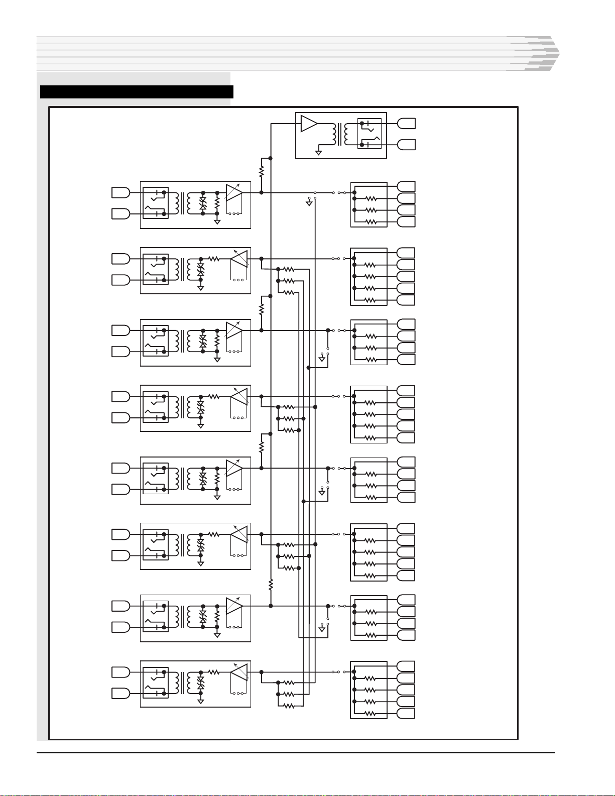
INSTALLATION
Checkout
Table B provides the checkout and calibration procedures for a
four-way/four-wire bridge. Use the following test equipment for
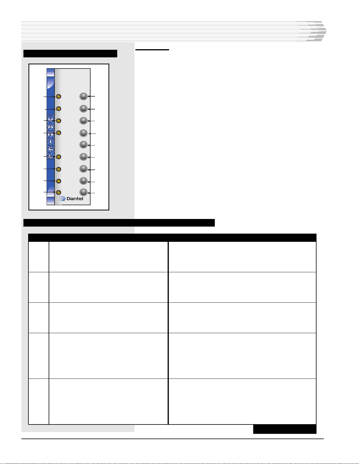
checkout (refer to Fig. 5 for a front panel view):
♦Signal generator
♦Two bantam jack test cables (a bantam plug on one end, and
a plug to fit the meter and generator on the other)
♦dB level meter with 600-ohm termination
TABLE B - FOUR-WAY/FOUR-WIRE BRIDGE APPLICATION CALIBRATION PROCEDURE
FIG. 5 - FRONT PANEL, 44118
A11-44118-
44118-00
DISTRIBUTION
BRIDGE
LINE RCV
PORT 1
PORT 2
PORT 3
PORT 4
COMBINED
DIST
OUTPUT
PORT 1
PORT 2
PORT 3
PORT 4
LINE XMT
44118-00 REV__
J1
J3
J5
J7
J9
J2
J4
J6J6
J8
R7
R24
R38
R54
R16
R31
R46
R62