Dantherm HCV7 User manual

1
092889•Version 1.1• 21.06.2016
HCV7
Service manual
Rev. 1.1
en

2
Der tages forbehold for trykfejl og ændringer
Dantherm can accept no responsibility for possible errors and changes
Irrtümer und Änderungen vorbehalten
Dantherm n’assume aucune responsabilité pour erreurs et modifications éventuelles

3
092889•Version 1.1• 21.06.2016
Introduction
Overview
Introduction
This is the service manual for the Dantherm Air Handling A/S home ventilation unit type
HCV7.
Table of contents
This manual covers the following topics:
Introduction................................................................................................................3
Overview..............................................................................................................3
General information .............................................................................................4
Product description.....................................................................................................5
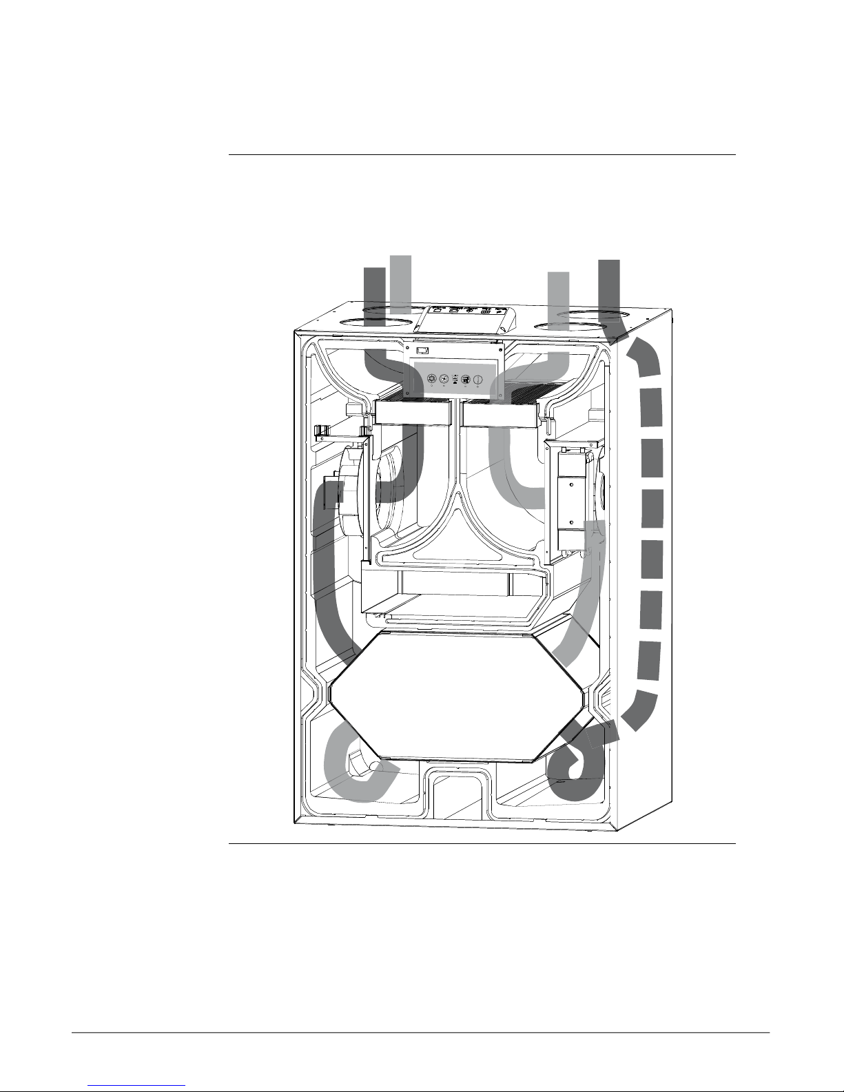
Overall description...............................................................................................5
Components description ......................................................................................8
Accessory description ........................................................................................10
Electronic control...............................................................................................11
System operation strategy..................................................................................14
Installation ...............................................................................................................15
Wall mounting....................................................................................................16
Water drainage...................................................................................................18
Connecting ducts...............................................................................................19
External connections..........................................................................................21
Swapping operation mode..................................................................................22
Initial calibration ................................................................................................24
Setting operation parameters .............................................................................25
Firmware update ................................................................................................26
User’s guide .............................................................................................................27
Overall ventilation functions...............................................................................28
Using the control panel ......................................................................................29
Using the LAN interface......................................................................................31
Service guide ............................................................................................................32
Overview............................................................................................................32
Preventive maintenance......................................................................................33
Error list ............................................................................................................36
Spare part list ....................................................................................................38
Technical information ...............................................................................................41
Technical data ...................................................................................................41
Wiring schematic................................................................................................42
Contact Dantherm..............................................................................................43

4
General information
Introduction
This section gives you the general information about this service manual and about the
unit.
Manual, part no.
Part number of this service manual is 092889
Target group
The target group for this service manual are:
The daily users
Technicians who install and maintain the unit
Copyright
Copying of this service manual, or part of it, is forbidden without prior written permis-
sion from Dantherm Air Handling A/S.
Reservations
Dantherm Air Handling A/S reserves the right to make changes and improvements to
the product and the service manual at any time without prior notice or obligation.
EU Declaration of
Conformity
Dantherm Air Handling A/S, Marienlystvej 65, DK-7800 Skive hereby declare that the
unit: 352443 HCV7
- complies with the following directives:
2014/35/EU...................... LVD Directive (low voltage)
2014/30/EU...................... EMC Directive
2014/53/EU...................... R&TTE
- and is manufactured in compliance with the following harmonized standards:
EN 60 335-1:201.............Household & similar electrical appliances, Safety - Part 1
EN 60 335-2-40:2003.....Household & similar electrical appliances, Safety - Part 2-40
EN 61 000-3-2:2014.......Electromagnetic compatibility (EMC) –Part 3-2: Limits
(Harmonics)
EN 61 000-3-3:2013.......Electromagnetic compatibility (EMC) –Part 3-3: Limits (Flicker)
EN 61 000-6-2:2005.......Electromagnetic compatibility (EMC) –Part 6-2: Generic standards (Im-
munity)
EN 61 000-6-3:2007.......Electromagnetic compatibility (EMC) –Part 6-3: Generic standards (Em-
mision)
EN 61 000-6-3/A1:2011..Electromagnetic compatibility (EMC) –Part 6-3: Generic
standards (Emmision)-Annex 1
EN 62 233:2008...............Measurement methods for electromagnetic fields of household applianc-
es
EN 55 014-1:2007...........Electromagnetic compatibility - Requirements of household appliances
etc. Part 1: Emission
EN 55 014-2:015.............Electromagnetic compatibility –Requirements of household appliances
etc. Part 2: Immunity –Product family standard
EN 30 1489-1..................EMC / ERM Part 1
EN 30 1489-3..................EMC / ERM Part 3
EN 30 0200-1:2013-02...EMC / ERM Short range Device Part 1
EN 30 0200-2:2013-02...EMC / ERM Short range Device Part 2
EN 30 0200-3:2013-02...EMC / ERM Short range Device Part 3
Skive, 24.05.2016
Recycling
Dantherm units are designed for long term durability. When total lifetime ends, the unit
should be recycled according to national rules and with high environmental protection
considerations.

5
092889•Version 1.1• 21.06.2016
Product description
Overall description
Introduction
This section gives you a description of the overall unit.
HCV7 overview
HCV7 ventilation unit is designed to supply fresh air to residential home, by exchanging
heat from outgoing air to incoming air, resulting in virtual no energy loss.
The unit is designed for installation in dry surroundings, with temperatures >12°C. e.g.
utility room or similar heated rooms.
The duct connections can be electronically swapped, providing ability to route the con-
nected ductwork, either to the right of to the left, as described on page 22 .
Use of shortages in
this manual
This manual uses shortages for ventilation terminologies
Short
Description
T1
Outside air coming into the unit
T2
Supply air going from unit to indoor
T3
Indoor extract air going into the unit for heat recovery
T4
Exhaust used air from unit to outside
S1
Temperature sensor no 1
S2
Temperature sensor no 2
S3
Temperature sensor no 3
S4
Temperature sensor no 4
A
Indicating operation mode Awhere the T2 and T3 is on the LEFT hand side of
the top of the unit. See more at page 22
B
Indicating operation mode Bwhere the T2 and T3 is on the RIGHT hand side
of the top of the unit. See more at page 22
G4
Standard air filter,
F7
Fine filter (Accessory)
BP
Bypass damper
IP
Unique address for the ethernet port.
DHCP
Automatic settings of an ethernet adresse provided from an external network
component ( if connecting the unit to Ethernet)
PC
Personel computer running MS Windows
USB
Universal serial bus connection–located on almost any computer
LAN
Local area network
WAN
Wide area network(internet)
Continued overleaf

6
Overall description, continued
Illustration
Fig. 1
Component
description
Part
Mode A
Mode B
Duct connection 1
Indoor extract air - T3
Outside air inlet –T1
Duct connection 2
Exhaust to outside –T4
Indoor supply air T2
Duct connection 3
Outside air inlet –T1
Indoor extract air T3
Duct connection 4
Indoor supply air - T2
Exhaust to outside T4
Filter 1
Extract filter G4
Supply filter G4 or F7
Filter 2
Supply filter G4 or F7
Extract filter G4
Fanbox 1
Extract fan
Supply fan*
Fanbox 2
Supply fan*
Extract fan
*Supply fanbox can be fitted with electrical preheat element (accessory)
Continued overleaf
Main PCB
Control panel
Filter 1
Filter 2
Fanbox 1
Fanbox 2
Bypass
Counterflow heat exchanger
Duct 1
Duct 2
Duct 3
Duct 4
Water drain –Mode B
Water drain –Mode A

7
092889•Version 1.1• 21.06.2016
Overall description, continued
Airflows
This illustration shows the two air flow paths, through the unit. The airflow direction
will change if changing operation mode. See more about changing operation mode at
page 22
Airflow 1
Airflow 2

8
Components description
Introduction
This section describes the individual components of the HCV7.
Please use the Fig. 1 illustration on page 5 for reference
Cabinet
Cabinet outer parts are made of aluzink coated sheet metal, finished with powder paint.
The inner part is one moulded polystyrene piece, which cannot be opened.
If adding accessory or exchanging parts, all access is available, just by removing the
front cover, and uses the internal polystyrene hatches for each part.
The cabinet is internal sound and heat insulated, with fire retardant polyester foam. The
unit´s cabinet is designed for mounting in 12°-40° C ambient temperature
Filters
The unit is standard equipped with class G4 cassette filter. These filters protects the
heat exchanger, and improves the inside environment by remove dust and particles, in
both airflows. F7 filter can be purchased. If F7 is used, this is always placed in the sup-
ply air, removing even smaller particles in the air. Correct placement of F7 filters ac-
cording mode selection, is shown on the connection label on the top of the unit.
Heat exchanger
The counter flow heat exchanger absorbs the heat energy from extract air and moves
this heat energy to the ingoing supply air, resulting in ventilation virtually without any
heat loss.
Fans
Supply air fan supply fresh outdoor air through the unit’s heat exchanger to the distri-
bution ducts, where it´s distributed to bedrooms, living rooms and possibly sauna or
steam bath.
The extract air fan draws used and moistened and polluted air from inside, through the
unit and heat exchanger, in which the heat is moved to supply air. Finally the air is ex-
hausted to the outside.
Water drainage
The unit is equipped with 2 pcs. spigot connections. One of these is mandatory to be
fitted with water hose connections, discharging the condensed water to a sever. A dou-
ble drainage spigot can be used (accessory), or a single one depending on selected run-
ning mode. Correct drainage is shown on the connection label on the top of the unit

9
092889•Version 1.1• 21.06.2016
Components description,
continued
Electronic control
Detailed description of the electronic controls on page 11 , and user guide page 25
Control part
illustration
Fig. 2
Component
description
pos
Mode A
Mode B
S1
T1 outside air inlet temperature sensor
T3 indoor extracted air temperature
sensor
S2
T2 indoor supply air temperature sen-
sor
T4 exhaust to outside temperature sen-
sor
S4
T4 exhaust to outside temperature
sensor
T2 indoor supply air temperature sensor
S3
T3 indoor extracted air temperature
sensor
T1 Outside air inlet temperature sensor
A
VOC and RH% sensor (accessory)
n/a (sealing pad)
B
n/a (sealing pad)
VOC and RH% sensor (accessory)
1
T1 outside air inlet pressure connec-
tion
T3 indoor extracted air pressure con-
nection
2
T2 indoor supply air pressure connec-
tion
T4 exhaust to outside air pressure con-
nection
3
T3 indoor extracted air pressure con-
nection
T1 outside air inlet pressure connection
4
T4 exhaust to outside air pressure
connection
T2 indoor supply air pressure connec-
tion
BP
Cable for by pass
Cable for by pass
S3
A
BP
3
2
S2
4
S4
S1
B
1

10
Accessory description
Installation of
accessories
The unit is delivered from factory, without any accessories mounted. These are to be in-
stalled prior to initial unit installation or alternative after commissioning, if further
functionality is requested.
The installation of one or more accessories is illustrated on a leaflet following each ac-
cessory.
Electric preheating
(accessory)
Preheats incoming air, by installing an electrical preheating element (accessory) The
preheater increases the outside air temperature going into the heat exchanger, and
thereby reduces the risk of ice in the heat exchanger in very cold conditions.
Humidity and VOC
sensors
(accessory)
This unit can be fitted with Humidity (RH%) and/or VOC (air quality) sensors (accessory).
These sensors will continuously monitor the quality of the extract air, and adjust the air
flow level accordingly. This is operation is named demand mode. If a HRC remote con-
trol is connected, the level will be shown in the display using 3 level icon.
Using demand mode will results in the correct level of ventilation with lowest possible
electrical power consumption.
When installing these sensors, the sealing pad initially blocking the mounting slot, is
turned 90°, and reveals then a routing path for the cable.
Bypass damper
(standard)
The motorized bypass damper overrides the heat exchanger functionality. This is used
in warm summer conditions, where colder outside air, can be used for reducing inside
temperature, when inside temperature exceeds an upper temperature limit.

11
092889•Version 1.1• 21.06.2016
Electronic control
Introduction
This section gives you a detailed description of the electronic control.
Function
The unit´s main controller is placed at the main PCB, together with I/O connections for
internal as well as external connections.
Control board with keypad and LED signals is placed below and connected to main PCB
with a non-extendable multicore cable.
System
architecture
This illustrates the overall system control architecture:
Continued overleaf
USB service port
Keypad with LED
Air quality demand
sensor
HRC 3 wireless
remote
Ethernet router with
DHCP
HAC1 on MODBUS
(Dantherm
accessory)
2 pce digital in
High/low fan speed
Smart Phone App´s
Main controller PCB
WG unit
Extract fan
T1-T4
Temperature
sensors
Supply fan
Air humidity(RH%)
demand sensor
Bypass 230VAC
Bypass 12VDC
Preheater 230VAC
Accessory modules
230VAC input
External connected items
Building
management
system
HCV7 unit

12
Electronic control, continued
Unit control
illustration
This drawing illustrates main pcb and control board:(with front cover is removed)
Connection
illustration
This drawing illustrates main pcb´s external connections:
Connection
description
This table describes the external connections:
Connection
Description
230V
Connection for 230V supply. Cable fitted with Schuko plug
DIGI IN
External digital input, to select operations
ANTENNA
Wireless connection point for proprietary remote control
MODBUS
Modbus connection for accessory modul
ETHERNET
LAN connection
continued overleaf
Main PCB
USB-B
for service
Control panel with LED
External
connections
Internal
connections

13
092889•Version 1.1• 21.06.2016
Electronic control,
continued
Control panel
illustration
Control panel
description
The foil keypad has four buttons with corresponding LED signal light below. Four blue
LED indicating the fan speed is situated in the middle. They will regardless of operation
conditions, always indicate the present fan speed. User manual page 27 describes oper-
ation of the unit in details.
1
2
3
4
5

14
System operation strategy
Introduction
This section describes the operation strategy in various conditions.
For a user specific running operation see user guide at page 27
Preheat
If preheater is installed, the unit can add electrical heat to the T1 incoming outside air,
in order to reduce defrost situations, and increase the supply air temperature.
Preheater can be enabled/disabled on the HRC3 in installer mode, if preheat
module is set to “present” in the pc tool when installing
Preheat is applied after the T1 sensor.
If outside temperature is <-3°C or supply air is < 16,5°C the preheater will
switch on with 10% power.
The power will increase/decrease 10% for each 60 seconds depending on the
T1 or T2 temperature.
Setpoints cannot be changed
Defrost
In cold conditions where T1 is below -3°C and exhaust T4 is <+2°C the condensed wa-
ter could built up as ice in the heat exchanger, blocking the air path and eventually de-
stroying the heat exchanger.
In order to prevent this sequence is initiated:
Apply additional heat with preheater if mounted
The supply fan speed will decrease with 3 rpm/second until minimum RPM is
reached.
After 10 seconds at this speed the supply fan will stop completely, while the
ongoing exhaust fan is supplying warmer air into the heat exchanger compo-
nent, to remove any potential ice.
When T4 yet again is >+8°C the supply fan will start at minimum RPM, and then
increase speed with 3 rpm/second until the original required speed is regained.
If T4 becomes <+2°C during the speed increase cycle, the supply fan will de-
crease speed again.
If T1<= -13°C for more than 4 minutes and 25 seconds, even with defrost
mode active, the unit will stop all operation for 30 minutes, and reattempt pre-
vious operation condition. If electrical built in preheat is present, this total off
mode is disabled.
The defrost operation will create an underpressure inside the house, so if fireplace
mode is enabled, and defrost is necessary; the unit will stop all operation in 4 hours in-
stead. Setpoints cannot be changed.
When defrost is active a HRC 3 will show dEF
When defrost has shut all off, the display will flash the T1 temperature
Bypass cooling and
summer mode
See more in the user guide page 27

15
092889•Version 1.1• 21.06.2016
Installation
Introduction
This section will guide you through unpacking, mounting and installation
Important
Warranty is restricted to units, installed by trained and certified personnel only.
Wrapping
HCV7 is delivered in a cardboard box. Please check packaging for damages before un-
packing.
Check content
Check the content of the box:
Step
Action
1
Unpack the unit carefully. Do not use a knife
2
The HCV7 is designed to be placed on a wall console bracket.
Installation
considerations
The following should be considered selecting an Appropriate location for installation:
The air flow direction can be electronically swapped, providing ability to route
the connected ductwork to and from the unit, either to the right of to the left.
See more in the Overall description at page 5.
This swapping function, provides ability to route the pair of ducts (outside or
inside) towards the unit from the left OR the right, according to building and
room layout
The HCV7 unit, is designed to mounted in dry surroundings, with temperatures
>12°C. Utility room or similar heated rooms.
Please allocate additional space, to ensure correct mounting and service ability.
Please ensure that the walls structure is adequate to withstand the unit addi-
tional weight, regardless of bracket type.
Continued overleaf

16
Wall mounting
Mounting wall
console bracket
Please follow these steps to mount the unit on the wall console brackets.
Step
Illustration
Fasten the wall
consoles, accord-
ing dimensions
Level the brackets
Continued overleaf

17
092889•Version 1.1• 21.06.2016
Wall mounting, continued
Mounting wall con-
sole bracket,
continued
Step
Illustration
Mount the four
damper bushings
Place the unit onto
the console brack-
ets, place washer-
and fasten the
nuts
Continued overleaf

18
Water drainage
Introduction
As the unit absorb the heat from the extracted air, air with high humidity will conden-
sate to water drops. This water is harmful to its surrounding if not managed correctly
Drainage connection
Connect a water drainage hose to the Appropriate water outlet spigot, in the bottom of
the unit. The unused spigot is to be closed with a blind.
The drainage hose has to be fitted with a water trap not smaller than 100 mm water
column, made as a loop or two bends on the hose.
Route the hose to Appropriate water sever, securing that the hose cannot freeze to ice.

19
092889•Version 1.1• 21.06.2016
Connecting ducts
Warning
The ducts must be covered and the unit must not be connected until the house is ready
for occupation, which means clean and dry. This is to prevent building dust and con-
densation from settling in the duct system and to prevent hygiene problems in the ven-
tilation unit at a later date.
Consideration
The ducts connected to the unit must have at least the same diameter as the unit's duct
connection or larger. Dimensions can be seen in the technical data section
Dimensions of ducts and sound absorbers must be in conformity with national stand-
ards and guidelines in the current building legislation. Contact your Dantherm dealer
for further advice.
Noise and vibrations from the unit to the ducts must be minimized. This can be
achieved by installing sound absorbers on both the supply and exhaust air sides.
Locate correct air
connection
Please consult the product description at page 5, as well as the label on the top cover,
to determine the correct duct connection
Connection
Connect duct items with spigot´s ONLY
Continued overleaf

20
Connecting ducts, continued
Insulation
Wrap minimum 50 mm insulation around all four ducts
Table of contents
Other Dantherm Dryer manuals
Popular Dryer manuals by other brands

EVVO
EVVO NATURE S8 instruction manual

Bosch
Bosch WTH85VP6SN User manual and installation instructions

Aroma
Aroma AFD-915BD user manual

Alliance Laundry Systems
Alliance Laundry Systems DV6010WE Installation & operation

American Dryer Corp.
American Dryer Corp. AD-120ES II installation manual

Roper
Roper Gas 120-Volt installation instructions