Dantherm AD 200 User manual

AD 200-300
SERVICE MANUAL
en • de • fr • da • pt Rev. 1.0 • 2020-W11-3


098985 • Version 1.0 • 11. 03 2020
3
en
Notes on this instruction manual
Table of contents
This service manual covers the following main topics:
Table of contents
Notes on this instruction manual ..................................................3
Table of contents......................................................................3
Overview .............................................................................4
Product description ..............................................................5
Overall description ....................................................................5
System operation strategy. . . . . . . . . . . . . . . . . . . . . . . . . . . . . . . . . . . . . . . . . . . . . . . . . . . . . . . . . . . . . 7
Installation. . . . . . . . . . . . . . . . . . . . . . . . . . . . . . . . . . . . . . . . . . . . . . . . . . . . . . . . . . . . . . . . . . . . . . .8
Safety. . . . . . . . . . . . . . . . . . . . . . . . . . . . . . . . . . . . . . . . . . . . . . . . . . . . . . . . . . . . . . . . . . . . . . . . . . . . . . . . . 8
Location, transport and installation ....................................................9
Installation. . . . . . . . . . . . . . . . . . . . . . . . . . . . . . . . . . . . . . . . . . . . . . . . . . . . . . . . . . . . . . . . . . . . . . . . . . . 11
User’s manual .................................................................. 13
Operation and operator control. . . . . . . . . . . . . . . . . . . . . . . . . . . . . . . . . . . . . . . . . . . . . . . . . . . . . . . 13
Service Guide .................................................................. 15
Maintenance and service .............................................................15
Troubleshooting .....................................................................17
Specications ........................................................................18
Spare parts ..........................................................................19
Enclosure dimensions ................................................................20
Schematics. . . . . . . . . . . . . . . . . . . . . . . . . . . . . . . . . . . . . . . . . . . . . . . . . . . . . . . . . . . . . . . . . . . . . . . . . . . 22
EU Declaration of Conformity .........................................................23

4
Overview
This is the service manual for the Dantherm product AD 200 / 300.
Please see the table of content on page 3 for further information about the sections.
This instruction manual addresses all technicians who install and maintain the AD 200 / 300 as
well as all end users. These persons must have read and understood the instruction manual.
The physical and psychological preconditions for proper and safety-conscious handling of the
devices must always be guaranteed.
Using a device outside the specied conditions and contrary to its designated use will lead to
the forfeiture of all warranty claims.
Dantherm reserves the right to make changes and improvements to the product and the
service manual at any time without prior notice or obligation.
Copying of this service manual, or part of it, is forbidden without prior written permission
from Dantherm.
In this instruction manual you will nd notes preceding the operating steps described to
warn you of possible hazards.
Type and source of hazard
This symbol in connection with the word“Danger”warns of a high risk of severe injury or
acute danger to life.
• Measures to avert danger or immediate measures if the risk occurs are described in this
way
Type and source of hazard
This symbol in connection with the word“Warning”warns of a risk involving severe injury.
• Measures to avert danger or immediate measures if the risk occurs are described in this
way
Type and source of hazard
This symbol in connection with the word“Caution” warns of a risk of minor or moderate injury
and material damage.
• Measures to avert danger or immediate measures if the risk occurs are described in this
way
In connection with this symbol you will nd further tips and information concerning the use
of the device.
Introduction
Target group
Warranty claims
Reservation
Copyright
Conventions
Warning
Caution
DANGER
Warning
Caution
WARNING
Warning
Caution
CAUTION
!TIP

098985 • Version 1.0 • 11. 03 2020
5
en
Product description
Overall description
This section contains an overall description regarding the usage of the Dantherm adsorption
dryer and optional components.
The adsorption dryers manufactured by Dantherm are designed exclusively for dehumidify-
ing air at atmospheric pressure in indoor rooms.
The AD 200 / 300 adsorption dryers can be operated in combination with a side channel
compressor or a noise box.
Operating the dehumidiers within the limits of designated use also involves observing the
specied operating conditions (refer to page 9).
Any use of the adsorption dryer not in conformity with or going beyond the designated use is
considered contrary to its designated use.
• Adsorption Dryer
• One instruction manual
Front- and back view of the adsorption dryers AD 200:
Fig. 1
Front- and back view of the adsorption dryers AD 300:
Fig. 2
Introduction
Designated use
Scope of delivery
Product
presentation
AD 200
1
7
3
2
8
9
6
4
5
Product
presentation
AD 300
2
1
7
8
6
9
3
4
5

6
Overall description, continued
The following table lists the dierent parts of the adsorption dryer according to the illustra-
tion Fig. 1 and Fig. 2 .
Pos. Description Pos. Description
1 Regeneration air outlet 6 Carrying handle
2 Hour meter 7 Process air intake
3 Performance counter in kWh for account-
ing the energy consumption
8 Connecting plate for dry air outlet
4 On / O switch 9 Connecting socket for power cable
5 Hygrostat
This illustration shows, where on the unit the dry air outlet is placed:
Fig. 3
The dry air is blown into the room through the connecting plate, either with or without con-
nected hoses as desired. Depending on the position of the connecting plate one or two hoses
can be connected.
Connecting one hose Connecting two hoses
Device description
Connecting plate
and dry air outlet

098985 • Version 1.0 • 11. 03 2020
7
en
System operation strategy
This section describes the operation strategy of the adsorption dryer.
The following diagram illustrates the method of operation of the adsorption dryer:
Fig. 4
The room air (= process air) taken in is fed through the turning adsorption rotor. The adsorp-
tion rotor is a high-performance rotor. By its metal silicate coating it has been optimised for
maximum water adsorption under dierent intake conditions. The slow rotation of the rotor
results in an automatic, continuous drying/regeneration process.
Due to its honeycomb structure the rotor features a very large surface. The mechanical
strength of the surface is extremely high. The rotor is non-combustible, maintenance-free and
washable.
The moisture taken up by the rotor is fed back out of the rotor by a heated air current (=
regeneration air) owing in the opposite direction.
The regeneration air is heated by a dynamic, safe and self-regulating PTC heating element.
The moist air current is discharged at the regeneration outlet (see Fig. 1 and Fig. 2) and must
be removed from the room via a hose or air duct (see page 12).
Introduction
Method of
operation Room air
(Proces air) Dry air
Regeneration air
(to be discharged
from the room)
Rotor PTC Heater
Adsorption rotor
Regeneration air
Regeneration air
outlet

8
Installation
Safety
This section describes the safety regulations which have to be followed when installing and
maintaining the adsorption dryer.
All persons involved in the installation, commissioning, operation and maintenance of the
devices must
• be properly qualied,
• closely observe the instructions set out in this manual.
Work on the internal components may only be carried out by the manufacturer or personnel
authorised by the manufacturer. This work involves danger of electric shock, burns, crushing,
entanglement and cutting.
Operation of or other work on the adsorption dryer incl. electrical equipment may only be
carried out by persons commissioned and instructed by the user. In the working area the
operator is responsible to third parties.
Responsibilities for the various activities on the device must be clearly dened and observed.
Unclear competencies are a safety risk. The user must:
• make the instruction manual accessible to the operator and
• make sure that the operator has read and understood the instruction manual.
The series AD 200 / 300 adsorption dryers were subjected to thorough safety testing.
Improper operation or misuse will cause danger to:
• the operator,
• the machine and other material property of the user,
• ecient operation of the machine.
Hoses and air lters must be properly installed and must not disable the protection devices of
the adsorption dryers. The operating elements must always be accessible.
Original spare parts or spare parts approved by the manufacturer shall exclusively be used.
Introduction
Safety devices
Authorized
operator
Risk of misuse
Hazards from
accessories

098985 • Version 1.0 • 11. 03 2020
9
en
Location, transport and installation
This section contains important information about the necessary operating conditions, trans-
port and installation of the adsorption dryers.
Series AD adsorption dryers are suited for mobile or stationary use on building sites, in stor-
age rooms, cellars, garages, on boats and in caravans. AD adsorption dryers work without
problems in the temperature range from -10 °C to +35 °C and in the humidity range from 10
% to 95 % relative humidity.
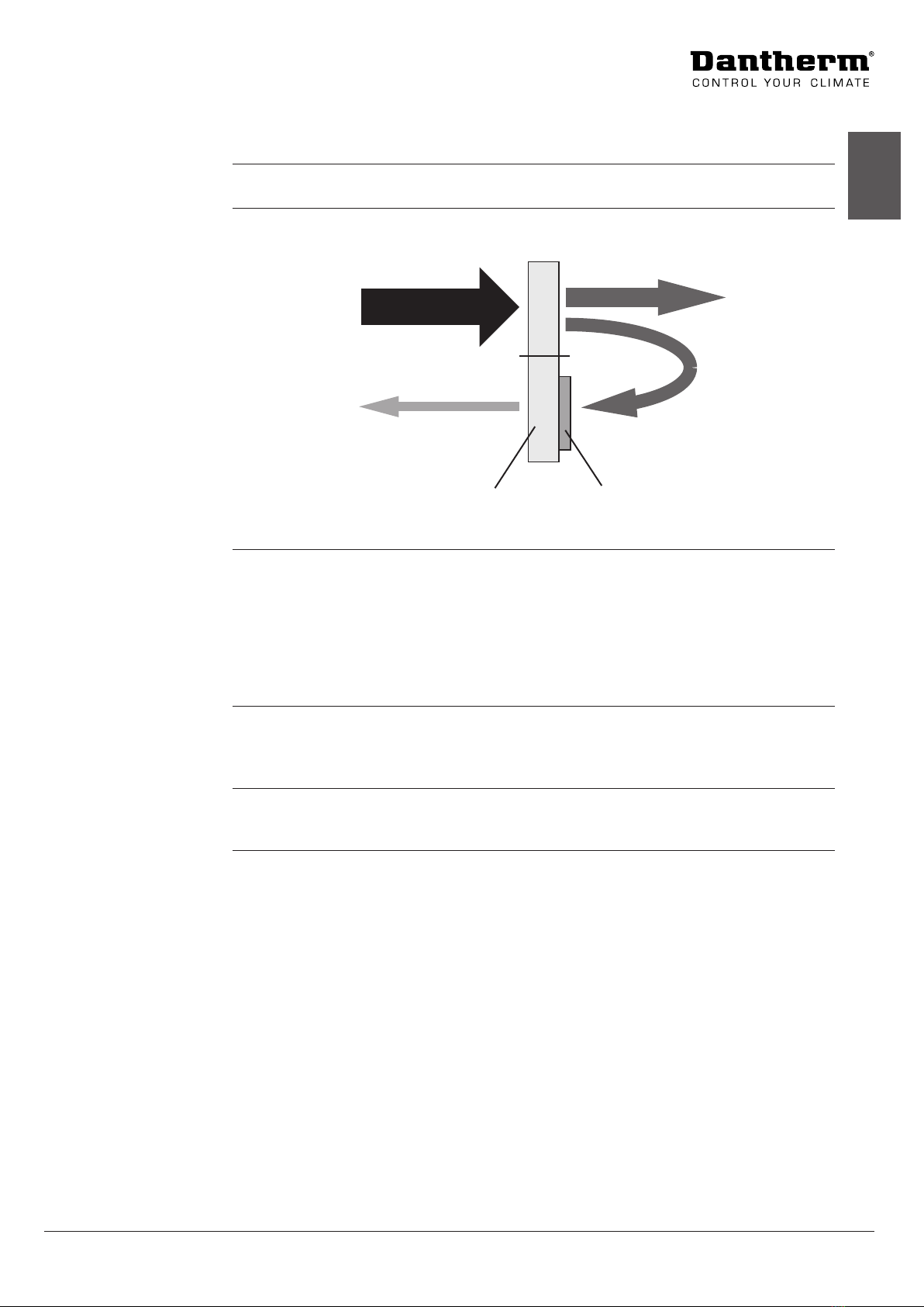
In case of connection and operation in accordance with its designated use the device gener-
ates a negative pressure in the operating room. As a result air, particles, smoke or gases can
be drawn in from outside or neighbouring rooms with potentially unexpected hazards due to
the eects on replaces and stoves or other equipment or due to any substances or materials
present there.
Assess this situation before using the adsorption dryer, and take appropriate preventive
measures, for example disconnection of devices or sealing-o of endangered rooms.
The devices must not be used under the following conditions:
• in rooms with potentially explosive atmospheres.
• in rooms with aggressive atmospheres, e.g. ammonia, wood acids, etc.
• in rooms with water with a pH value outside the range from 7.0 to 7.4.
• In case of lower pH values there is risk of corrosion for all metals and risk of damage to
mortar-containing materials (joints). Higher pH values cause skin and mucous mem-
brane irritations and increased lime deposits.
• in rooms with salt or liquids with a salt content > 1% (incl. brine baths).
• in rooms with ozone-treated air.
• in rooms with high solvent concentration.
• in rooms with extreme dust load.
Step Action
1Report any obvious damage to the carrier, parcel service, postal service etc. im-
mediately on delivery and note down the damage on the shipping document or
carrier’s document.
2Remove the packaging material completely and dispose of according to the local
regulations.
3Should any transport damage be detected after unpacking of the device, or
should the delivery be incomplete, contact your salesman in charge or specialised
dealer without delay.
4Use the carrying handle to transport the adsorption dryer to the place of installa-
tion.
Crushing hazard!
The adsorption dryer is heavy.
• Use only the handle to carry the adsorption dryer.
• Do not reach into the openings.
Material damage
Pulling the power cable may damage the cable.
• Always disconnect the mains plug from the socket outlet before transport of the device.
• Always use the carrying handle to lift the device.
Introduction
Areas of
application
Choosing the right
location
Inadequate loca-
tions
Transport
Warning
Caution
WARNING
Warning
Caution
CAUTION

10
During installation of the adsorption dryers the following points must be observed:
• The adsorption dryer must be installed on a horizontal, rm ground.
• Avoid rough handling to prevent damage to the casing.
• The adsorption dryer must be installed in such a way that free air circulation through the
device is guaranteed. The air lter must not be blocked.
• Switch o the device via the on/o switch and disconnect the power plug from the socket
outlet before moving the device.
• The adsorption dryer is equipped with a carrying handle for easy carrying.
In case of doubts about the operating conditions your technical advisor can help you.
Damage to appliance due to improper operating conditions
• Put the device gently down.
• Place the device on rm ground only.
• Always use the carrying handle to lift the device.
• Free air circulation must be guaranteed and the lter must not be covered.
Installation
Warning
Caution
CAUTION
Location, transport and installation, continued

098985 • Version 1.0 • 11. 03 2020
11
en
Installation
This section describes how to install the electrical connection of the series AD 200 / 300 ad-
sorption dryers correctly
The following items must be checked prior to electrical connection of the adsorption dryer:
• Is the mains voltage in conformity with the voltage of the device?
• Are socket and supply system suciently fused?
• Has an RCCB been installed?
• Is the appliance coupler suitable for the building socket outlet?
• Is the socket outlet used grounded properly?
Step Action Illustration
1 Connect the appliance coupler of the power cable included in
the delivery to the socket on the adsorption dryer.
2 Connect the power cable of the adsorption dryer to a suitable
power outlet.
Danger to life due to electric shock
• Prior to commissioning the technical data of the adsorption dryer must be compared with
the conditions prevailing in the room of installation!
• Use exclusively the original power cable! In case of loss or damage original power cables
are available from your adsorption dryer supplier.
Introduction
Electrical
connection
Warning
Caution
DANGER

12
Installation, continued
The dry air can be blown into the room, or one hose or alternatively two hoses can be con-
nected. Follow these steps in order to connect hoses to the dry air outlet.
Step Action Illustration
1 Decide if you want to connect one
hose (option A) or two hoses (option
B). Check if the position of the con-
necting plate for dry air outlet is in
accordance.
2 If the connecting plate has to be turned follow the next steps.
3 Release thumbscrews at the bottom
and top of the connection plate.
4 Turn connection plate.
5 Retighten connection plate using the thumbscrews.
A hose / air duct (not included in the scope of delivery) must be connected to the regenera-
tion air outlet (see position of the regeneration air outlet in Fig. 1 and Fig. 2).
The optimum length of the hose/air duct is 3 – 5 metres.
Step Action Illustration
1 Install the regeneration air hose with a slope away
from the adsorption dryer to prevent that any
condensate probably occurring in the hose cannot
get into the device.
2 If installation with a slope is impossible, drill a hole
(D = 4 mm) at the lowest point of the bend. If water
occurs in the hose due to condensation (in case
of very cold outside conditions) it can drain o
through this hole.
3 Feed the air discharge hose / duct out of the building.
Insucient device performance due to escaping air
• Fix the connected hoses using hose clamps.
Connection of
hoses / air ducts
- Dry air
AB
Connection of
hoses / air ducts
- Regeneration air
Warning
Caution
CAUTION

098985 • Version 1.0 • 11. 03 2020
13
en
User’s manual
Operation and operator control
This section describes the operating elements and setting options of the adsorption dryers.
Danger of injury and damage to appliance
Inadmissible ambient conditions or improper operation of the device may constitute a risk.
• Read the instruction manual before commissioning the adsorption dryer.
The following illustrations show the operating panel of the AD 200 and AD 300.
AD 200 AD 300
kWh
h
20% 40%
60%
80%
h
kWh
20%
40%
60%
80%
Description of the operating elements:
Pos. Description
1 Regeneration air outlet
2 Hour meter
3 Hygrostat
4 Performance counter in kWh for accounting the energy consumption
5 On / O switch
The Hour meter may not be used for the accounting of energy consumption. The perfor-
mance counter in kWh is calibrated and MID approved and thus can be used for the account-
ing of energy consumption.
Introduction
Warning
Caution
CAUTION
Operating
elements
AD 200/ 300
1
5
2
34
1 2 4 5
3
!TIP

14
Operation and operator control, continued
This illustration shows the hygrostat controller of the AD 200 and AD 300.
kWh
h
20%
40%
60%
80%
h
kWh
20%
40%
60%
80%
Fig. 5
The hygrostat controller of the device can be used to set the desired humidity value. The
hygrostat is arranged clearly visible in the operating panel.
Continuous adjustment of the hygrostat allows for easy humidity control.
Hygrostat position Signicance, device response
Position 0 Device ready for operation
Position I Device running in continuous mode
Position 80% The adsorption dryer will switch o at a
relative room humidity of about 80% and
switch on again when a humidity of 80% is
exceeded.
Position 60% The adsorption dryer will switch o at a
relative room humidity of about 60% and
switch on again when a humidity of 60% is
exceeded.
Position 40% The adsorption dryer will switch o at a
relative room humidity of about 40% and
switch on again when a humidity of 40% is
exceeded.
Position 20% The adsorption dryer will switch o at a
relative room humidity of about 20% and
switch on again when a humidity of 20% is
exceeded.
If very precise setting values are required, use a hygrometer with a precise humidity display to
set the hygrostat.
For quick building drying the hygrostat is set to continuous operation (item I).
For drying and keeping rooms with wood furnishing (e. g. parquet ooring) or paintings,
antiques etc. dry, a minimum moisture of 55 – 60% must be observed.
In case of doubt please contact your technical advisor.
Damage to the device
• When the adsorption dryer is used in combination with a side channel compressor / noise
box: always set the hygrostat to position I.
Select the desired humidity on the hygrostat (Fig. 5) and switch the adsorption dryer on via
the On / O switch (Fig. 1 and Fig. 2). The On / O switch lights when the device is switched
on. When the drying process has been nished switch the device o via the On / O switch.
Hygrostat control
AD 300AD 200
Adjusting
the hygrostat
controller
!TIP
!TIP
Warning
Caution
CAUTION
Activating /
deactivating the
drying process

098985 • Version 1.0 • 11. 03 2020
15
en
Service Guide
Maintenance and service
This section describes the process of maintaining the adsorption dryers including the overall
safety precautions which have to be taken during maintenance work.
The cleaning intervals depend largely on the operating conditions. Therefore check your
adsorption dryer after every drying process.
If required, the inside of the device can be carefully cleaned with compressed air. Wear pro-
tective goggles and ensure that all internal components are cleaned.
• Rotor, rotor drive, drive belt, fan, heater and hygrostat (if any) must be checked at regular
intervals.
The device casing can be opened and inspected after removal of the screws and taking o
the lid.
Fig. 6
In order to guarantee trouble-free functioning of the adsorption dryer the device must be
cleaned and checked (in particular the air lter) at regular intervals.
• If the adsorption dryer is used as building dryer it is recommended to change the lter
every three days to ensure ecient drying.
Follow these steps when changing the lter:
Step Action Illustration
1 Remove the process air intake by loosen-
ing the thumbscrew.
2 Remove the lter as shown and replace it
by a new one.
3 Remount the process air intake and close
the device casing.
Fig. 7
Introduction
Cleaning and
inspection
Opening the
device
Checking /
changing the air
lter

16
Maintenance and service, continued
Danger of injury by electric shock and risk of material damage
• Always observe the general safety instructions when performing any maintenance and
service work!
• Switch the device o and pull the power plug before cleaning and inspection.
• Inspection and any work inside the device may only be carried out by trained expert sta.
Danger of injury due to dirt whirled up and compressed air
• Wear protective goggles during cleaning with compressed air!
Danger of cutting when reaching into inlet or outlet openings.
Danger of cut injuries at air inlet and outlet.
• Do not reach into the openings; carry the device exclusively by the handle.
Dust hazard
During cleaning with compressed air dust is released into the atmosphere.
• Clean air lter from outside and inside with a vacuum cleaner, if necessary wash and dry it.
• Clean device with compressed air only in an open environment; wear protective mask and
protective goggles.
Damage to the device
Cleaning agents can cause damage to surfaces.
• Use only mild detergents.
• Never operate the adsorption dryer without lter or when the lter is soiled.
Warning
Caution
WARNING
Warning
Caution
WARNING
Warning
Caution
CAUTION
Warning
Caution
CAUTION
Warning
Caution
CAUTION

098985 • Version 1.0 • 11. 03 2020
17
en
Troubleshooting
This section helps you identifying the cause of an occurred problem and gives advices of how
to solve it.
If problems arise with the adsorption dryer please check the following points. Should the
fault not be located please contact your technical advisor.
Problem Possible cause Remedy
Adsorption dryer does not
work / no air current can be
felt at dry air outlet and at
regeneration air outlet / no
air noise can be heard
Adsorption dryer switched
o
Switch adsorption dryer on
using the On / O switch
Power supply interrupted Check power supply, power
cable, power outlet and
device fuse
The humidity set on the hy-
grostat has been reached.
The adsorption dryer will au-
tomatically re-start when the
set humidity is exceeded.
Air lter clogged Change the air lter (see
page 15)
Rotor drive defective / drive
belt torn
Entrust a specialised com-
pany with the repair of the
adsorption dryer
The desired humidity is not
achieved / the device does
not automatically switch o
although the hygrostat is
connected
The device is not suciently
dimensioned
Ask your specialised dealer
to calculate the capacity re-
quired for your application.
There is very much humidity
in the masonry or in the oor
The adsorption dryer will
need some time to remove
the water and achieve an ac-
ceptable value in the room.
The regeneration air has the
same temperature as the dry
air / the desired humidity is
not achieved.
Heater defective Entrust a specialised com-
pany with the repair of the
adsorption dryer.
The drying performance of the adsorption dryer largely depends on the operating conditions.
Part of the air taken in by the adsorption dryer from the room is discharged from the room
with the regeneration air. As a result, negative pressure builds up in the room which causes
the corresponding amount of outside air to ow in.
The adsorption dryer can achieve very low humidity values in the dry air outlet (at intake
20 °C / 60% r.h. for example about 30 °C / 20% r.h.), but due to the outside air owing in the
humidity in the complete room will never reach the low value of the dry air.
Danger of injury by electric shock and risk of material damage
• The device may only be repaired by trained specialised sta. Within the warranty period,
any work on the dehumidier shall only be carried out by the manufacturer or persons
commissioned by the manufacturer. Any work carried out by unauthorised persons shall
lead to the forfeiture of all warranty claims!
Danger of cutting when reaching into inlet or outlet openings.
Danger of cut injuries at air inlet and outlet.
• Do not reach into the openings; carry the device exclusively by the handle.
Introduction
Identifying the
problem
!TIP
Warning
Caution
WARNING
Warning
Caution
CAUTION

18
Specications
AD 200 AD 300
Power supply 230 V / 50 Hz
Protection class IP 23
Dry air rate 210 cbm/h 300 cbm/h
Regulation air volume 110 cbm/h
Dehumidifying performance
at 20 °C / 60 % relative hu-
midity
18,75 kg/day 25,7 kg/Tag
Dehumidifying performance
in litres per kWh
1,13 l/kWh 1,05 l/kWh
Dehumidifying performance
in kWh per litre
0,89 kWh/l 0,97 kWh/l
Power supply max. 690 W 1100 W
Rotor dimensions
(Ø in mm / depth in mm)
200 / 60 260 / 50
Rotor speed 30 r/h
External pressure reg. air 50 pa
External pressure dry air 150 pa
Weight 14 kg 18 kg
Many dierent components installed in an adsorption dryer decide on its dehumidifying
performance.
Since these components can never be completely identical the actual performance according
to DIN EN 810 may deviate by up to 5% from the specied performance.
Overview
!TIP

098985 • Version 1.0 • 11. 03 2020
19
en
Spare parts
Spare parts for the AD 200/ 300 unit shown in this section, are available via Dantherm dealers.
1234
67
5
89
10 11 12 13 14 15 16 17
18
2
Fig. 8
This table shows all available spare parts with order numbers, according to Fig. 8.
Pos. Part name AD 200
(order no.)
AD 300
(order no.)
1 Hour meter and energy counter 099289
2 Thumbscrew M5x15 099290
3 Hose 80 mm 099291
4 Clip for hose 099292
5 Capacitor 2 µF 099293 099294
6 OT-thermo switch 150° 099295
7 Heating coil - PTC 099298
8 Switch 099299 099300
9 Hygrostat 099301
10 Air inlet 099302 099303
11 Air lter 099304 099305
12 Radial fan 099306 099307
13 Gear motor 099308
14 V-belt 285 mm 099309 099310
15 V-belt Pulley 099311
16 Rotor 099312 099313
17 Dry air outlet 099314 099315
18 Power cord 099316
Introduction

20
Enclosure dimensions
This illustrates the dimensions of the AD 200 unit:
Ø 78
Ø 125
285
257
Ø 78
Ø 50
Ø 50
326
289
Fig. 9
Dimension
illustration AD 200
This manual suits for next models
1
Table of contents
Languages:
Other Dantherm Dryer manuals