Danyon DA-HP-16-230 Installation instructions

INSTALLATION
AND OWNER’S MANUAL
Air to Water Heat Pump System Tri-Thermal Monobloc
IMPORTANT NOTE:
Thank you very much for purchasing our product.
Before using your unit, please read this manual carefully and keep it for future reference.

CONTENTS
1 SAFETY PRECAUTIONS .................................................................................................. 01
2 BEFORE INSTALLATION.................................................................................................. 05
3 IMPORTANT INFORMATION FOR THE REFRIGERANT ................................................ 05
4 INSTALLATION SITE......................................................................................................... 05
5 INSTALLATION PRECAUTIONS ...................................................................................... 08
6 OVERVIEW OF THE UNIT................................................................................................. 11
7 TEST RUN AND FINAL CHECKS ..................................................................................... 26
8 MAINTENANCE AND SERVICE ..................................................................................... 26
9 TURN OVER TO CUSTOMER ......................................................................................... 27
10 OPERATION AND PERFORMANCE............................................................................... 28
11 ERROR CODES............................................................................................................... 29
12 TECHNICAL SPECIFICATIONS...................................................................................... 34
13 INFORMATION SERVICING............................................................................................ 42

1 SAFETY PRECAUTIONS
01
The precautions listed here are divided into the following types. They are quite important, so be sure to follow them carefully. Read these
instructions carefully before installation. Keep this manual well for future preference.
Meanings of DANGER, WARNING, CAUTION and NOTE symbols.
Indicates an imminently hazardous situation which if not avoided, will result in death or serious injury.
• Read these instructions carefully before installation. Keep this manual handy for future peference.
• Improper installation of equipment or accessories may result in electric shock, short-circuit, leakage, fire or other damage to the equip-
ment.
• Be sure to only use accessories made by the supplier, which are specifically designed for the equipment and ensure that the installation
is completed by professionals.
•All the activities described in this manual must be carried out by licensed technicians. Be sure to wear adequate personal protection
equipment such as gloves and safety glasses while installing the unit or carrying out maintenance activities.
• Contact your dealer for any further assistance.
• Improper installation of equipment or accessories may result in electric shock, short-circuit, leakage, fire or other damage to the
equipment. Be sure to only use accessories made by the supplier, which are specifically designed for the equipment and make sure
to get installation done by a certified person.
•All the activities described in this manual must be carried out by a licensed technician. Be sure to wear adequate personal protection
equipment such as gloves and safety glasses while installing the unit or carrying out maintenance activities.
Indicates a potentially hazardous situation which if not avoided, could result in death or serious injury.
Indicates a potentially hazardous situation which if not avoided, may result in minor or moderate injury.It is also used to alert against unsafe
practices.
Indicates situations that could only result in accidental equipment or property damage.
INFORMATION
DANGER
WARNING
WARNING
CAUTION
NOTE

02
Servicing shall only be performed as recommended by the equipment manufacturer. Maintenance and repair requiring the assistance of
other skilled personnel shall be carried out under the supervision of the person competent in the use of flammable refrigerants.
Caution:Risk of fire/
flammable materials
• Do not have refrigerant leakage and open flame.
• Be aware that the R32 refrigerant does NOT contain an odour.
The appliance shall be stored so as to prevent mechanical damage and in a well-ventilated room without continuously operating ignition
sources (example:open flames,an operating gas appliance) and have a room size as specified below.
Special requirements for R32
• Pipework should be protected from physical damage.
• Installation of pipework shall be kept to a minimum length.
Make sure installation,servicing,maintenance and repair comply with instruction and with applicable legislation(for example national gas
regulation) and are executed only by authorized persons.
WARNING
WARNING
WARNING
WARNING
NOTE

03
Explanation of symbols displayed on the monobloc
WARNING
CAUTION
CAUTION
CAUTION
CAUTION
This symbol shows that this appliance used a flammable refrigerant. If the refrigerant is leaked and
exposed to an external ignition source,there is a risk of fire.
This symbol shows that the operation manual should be read carefully.
This symbol shows that service personnel should handle this equipment with reference to the installation
manual.
This symbol shows that a service personnel should be handling this equipment with reference to the
installation manual.
This symbol shows that information is available such as the operating manual or installation manual.
• Before touching electric terminal parts, turn off power switch.
• When service panels are removed, live parts can be easily touched by accident.
• Never leave the unit unattended during installation or servicing when the service panel is removed.
• Do not touch water pipes during or immediately after operation as the pipes may be hot and could burn your hands. To avoid injury, wait
until the pipes cool down to odinary temperature or be sure to wear protective gloves.
• Do not touch any switch with wet hands. Touching the switch with wet hands can cause electrical shock.
• Before touching electrical parts, turn off all applicable power to the unit.
•Tear apart and throw away plastic packaging bags so that children will not play with them.Children playing with plastic bags face
danger of death by suffocation.
• Safely dispose of packing materials such as nails, other metal and wood parts that could cause injuries.
•Ask your dealer or qualified personnel to perform installation work in accordance with this manual. Do not install the unit by yourself.
Improper installation could result in water leakage, electric shocks or fire.
• Be sure to use only specified accessories and parts for installation work. Failure to use specified parts may result in water leakage,
electric shocks, fire, or the unit falling from its mount.
• Install the unit on a foundation that can withstand its weight. Insufficient physical strength may cause the equipment to fall and
possible cause injury.
• Perform specified installation work with full consideration of strong wind, hurricanes, or earthquakes. Improper installation work may
result in accidents due to equipment falling.
• Make certain that all electrical work is carried out by qualified personnel according to the local laws and regulations and this manual
using a separate circuit. Insufficient capacity of the power supply circuit or improper electrical construction may lead to electric
shocks or fire.
• Be sure to install a ground fault circuit interrupter according to local laws and regulations. Failure to install a ground fault circuit
interrupter may cause electric shocks and fire.
• Make sure all wirings are secure. Use the specified wires and ensure that terminal connections or wires are protected from water and
other adverse external forces. Incomplete connection or affixing may cause a fire.
• When wiring the power supply, form the wires so that the front panel can be securely fastened. If the front panel is not in place there
could be overheating of the terminals, electric shocks or fire.
•After completing the installation work, check to make sure that there is no refrigerant leakage.
• Never directly touch any leaking refrigerant as it could cause severe frostbite. Do not touch the refrigerant pipes during or
immediately after operation as the refrigerant pipes may be hot or cold, depending on the condition of the refrigerant flowing through
the refrigerant piping, compressor and other refrigerant cycle parts. Burns or frostbite are possible if you touch the refrigerant pipes.
To avoid injury, give the pipes time to return to normal temperature. If you must touch them, be sure to wear protective gloves.
• Do not touch the internal parts (pump, backup heater, etc.) during or immediately after operation. Touching the internal parts will
cause burns. To avoid injury, give the internal parts time to return to normal temperature. If you must touch them, be sure to wear
protective gloves.
WARNING
DANGER

04
•About Fluorinated Gases
-This heat pump unit contains fluorinated gases. For specific information on the type of gas and the amount, please refer to the
relevant label on the unit itself. Compliance with national gas regulations shall be observed.
- Installation, service, maintenance and repair of this unit must be performed by a certified technician.
- Product uninstallation and recycling must be performed by a certified technician.
- If the system has a leak-detection system installed, it must be checked for leaks at least every 12 months. When the unit is checked
for leaks, proper record-keeping of all checks is strongly recommended.
• Ground the unit.
• Grounding resistance should be according to local laws and regulations.
• Do not connect the ground wire to gas or water pipes, lightning conductors or telephone ground wires.
• Incomplete grounding may cause electric shocks.
- Gas pipes:Fire or an explosion may occur if the gas leaks.
-Water pipes:Hard vinyl tubes are not effective grounds.
- Lightning conductors or telephone ground wires:Electrical threshold may rise abnormally if struck by a lightning
bolt.
• Install the power wire at least 3 feet (1 meter) away from televisions or radios to prevent interference or noise. (Depending on the radio
waves, a distance of 3 feet (1 meter) may not be sufficient to eliminate the noise.)
• Do not wash the unit. This may cause electric shocks or fire. The appliance must be installed in accordance with national wiring
regulations. If the supply cord is damaged, it must be replaced by the manufacturer, its service agent or similarly qualified persons in
order to avoid a hazard.
• Do not install the unit in the following places:
- Where there is mist of mineral oil, oil spray or vapors. Plastic parts may deteriorate, and make them become loose or water leakage.
- Where corrosive gases (such as sulphurous acid gas) are produced. Where corrosion of copper pipes or soldered parts may cause
refrigerant to leak.
- Where there is machinery which emits electromagnetic waves. Electromagnetic waves can disturb the control system and cause
equipment malfunction.
- Where flammable gases may leak, where carbon fiber or ignitable dust is suspended in the air or where volatile flammables such as
paint thinner or gasoline are handled. These types of gases might cause a fire.
- Where the air contains high levels of salt such as near the ocean.
- Where voltage fluctuates a lot, such as in factories.
- In vehicles or vessels.
- Where acidic or alkaline vapors are present.
• This appliance can be used by children 8 years old and above and persons with reduced physical, sensory or mental capabilities or lack
of experience and knowledge if they are supervised or given instruction on using the unit in a safe manner and understand the hazards
involved. Children should not play with the unit. Cleaning and user maintenance should not be done by children without supervision.
• Children should be supervised to ensure that they do not play with the appliance.
• If the supply cord is damaged, it must be replaced by the manufacturer or its service agent or a similarly qualified person.
• DISPOSAL: Do not dispose this product as unsorted municipal waste. Collection of such waste separately for special treatment is
necessary. Do not dispose of electrical appliances as municipal waste, use separate collection facilities. Contact your local government
for information regarding the collection systems available. If electrical appliances are disposed of in landfills or dumps, hazardous
substance can leak into the groundwater and get into the food chain, damaging your health and well-being.
•The wiring must be performed by certified person technicians in accordance with national wiring regulation and this circuit diagram. An
all-pole disconnection device which has at least 3mm separation distance in all pole and a residualcurrent device(RCD) with the rating
not exceeding 30mA shall be incorporated in the fixed wiring according to the national rule.
• Confirm the safety of the installation area ( walls, floors, etc. ) without hidden dangers such as water, electricity, and gas before
wiring/pipes.
• Before installation, check whether the user's power supply meets the electrical installation requirements of unit ( including reliable
grounding, leakage, and wire diameter electrical load, etc. ). If the electrical installation requirements of the product are not met, the
installation of the product is prohibited until the product is rectified.
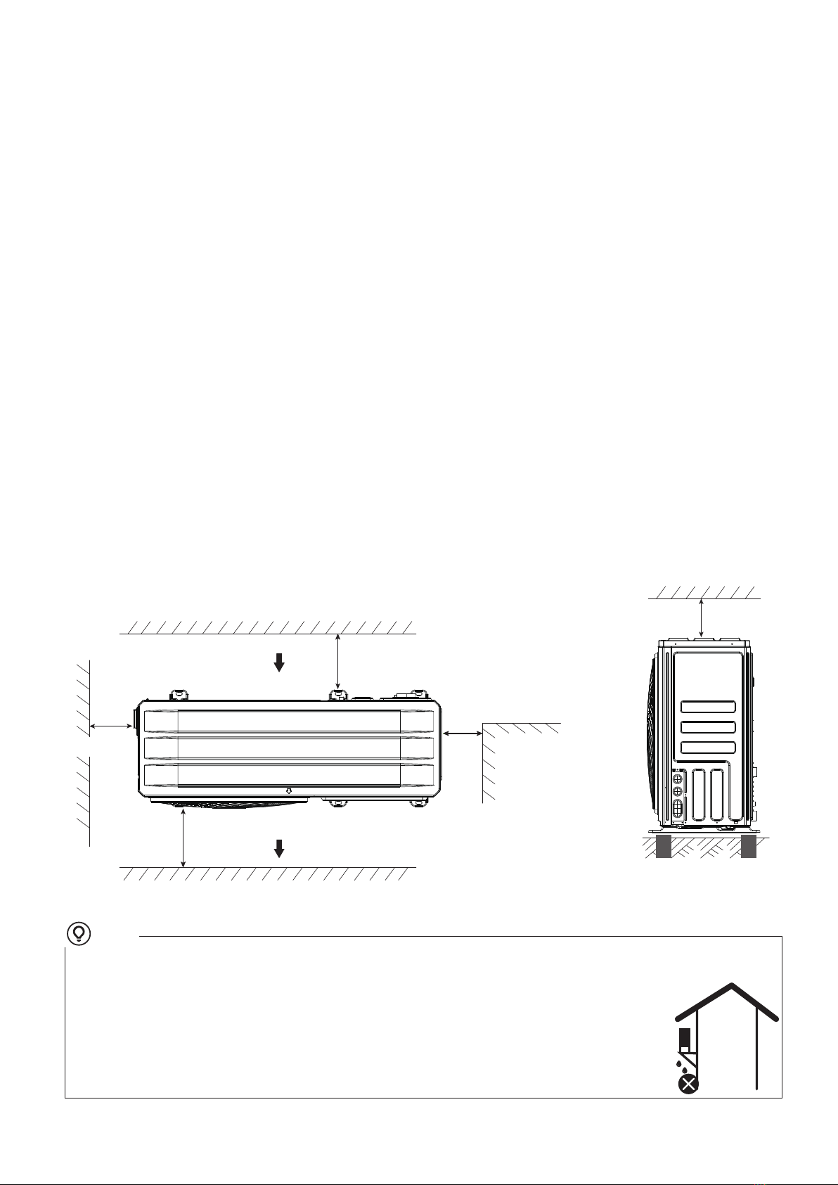
• Product installation should be fixed firmly. Take reinforcement measures when necessary.
NOTE
CAUTION

2 BEFORE INSTALLATION
3 IMPORTANT INFORMATION FOR THE REFRIGERANT
4 INSTALLATION SITE
05
Before installation
Be sure to confirm the model name and the serial number of the unit.
• There is flammable refrigerant in the unit and it should be installed in a well-ventilated site. If the unit is installed inside, an additional
refrigerant detection device and ventilation equipment must be added in accordance with the standard EN378. Be sure to adopt
adequate measures to prevent the unit from being used as a shelter by small animals.
• Small animals making contact with electrical parts can cause malfunction, smoke or fire. Please instruct the customer to keep the area
around the unit clean.
• The equipment is not intended for use in a potentially explosive atmosphere.
This product has the fluorinated gas, it is forbidden to release to air.
Refrigerant type: R32; Volume of GWP: 675.
GWP=Global Warming Potential
Refrigerant/kg
Factory charged refrigerant volume in the unit
Model Tonnes CO2equivalent
1.4
8kW
0.95
1.4
10kW 0.95
• Frequency of Refrigerant Leakage Checks
- Equipment that contains less than 3 kg of fluorinated greenhouse gases or hermetically sealed equipment, which is labelled
accordingly and contains less than 6 kg of fluorinated greenhouse gases shall not be subject to leak checks.
- For unit that contains fluorinated greenhouse gases in quantities of 5 tonnes of CO2equivalent or more,but of less than 50 tonnes of
CO2equivalent,at least every 12 months, or where a leakage detection system is installed, at least every 24 months.
- Only certificated person is allowed to do installation, operation and maintenance.
Frequency of Refrigerant Leakage Checks
- For unit that contains fluorinated greenhouse gases in quantities of 5 tonnes of CO2equivalent or more,but of less than 50 tonnes of CO2
equivalent,at least every 12 months, or where a leakage detection system is installed, at least every 24 months.
- For unit that contains fluorinated greenhouse gases in quantities of 50 tonnes of CO2equivalent or more, but of less than 500 tonnes of
CO2equivalent at least every six months, or where a leakage detection system is installed, at least every 12 months.
- For unit that contains fluorinated greenhouse gases in quantities of 500 tonnes of CO2equivalent or more,at least every three months, or
where a leakage detection system is installed,at least every six months.
- This heat pump unit is a hermetically sealed equipment that contains fluorinated greenhouse gases.
- Only certificated person is allowed to do installation, operation and maintenance.
WARNING
CAUTION
CAUTION
1.74
1.74
1.74
12kW
14kW
16kW
1.18
1.18
1.18

06
Select an installation site where the following conditions are satisfied and one that meets with your customer's approval.
- Places that are well-ventilated.
- Places where the unit does not disturb next-door neighbors.
- Safe places which can bear the unit's weight and vibration and where the unit can be installed at an even level.
- Places where there is no possibility of flammable gas or product leak.
- The equipment is not intended for use in a potentially explosive atmosphere.
- Places where servicing space can be well ensured.
- Places where the units' piping and wiring lengths come within the allowable ranges.
- Places where water leaking from the unit cannot cause damage to the location (e.g. in case of a blocked draining pipe).
- Places where rain can be avoided as much as possible.
- Do not install the unit in places often used as a work space. In case of construction work (e.g. grinding etc.) where a lot of dust is created, the unit
must be covered.
- Do not place any object or equipment on top of the unit (top plate).
- Do not climb, sit or stand on top of the unit.
- Be sure that sufficient precautions are taken in case of refrigerant leakage according to relevant local laws and regulations.- Don’t install the unit
near the sea or where there is corrosion gas.
When installing the unit in a place exposed to strong wind, pay special attention to the following.
Strong winds of 5 m/sec or more blowing against the unit's air outlet causes a short circuit (suction of discharge air), and this may have the
following consequences:
- Deterioration of the operational capacity.
- Frequent frost acceleration in heating operation.
- Disruption of operation due to rise of high pressure.
- Motor burnout.
- When a strong wind blows continuously on the front of the unit, the fan can start rotating very fast until it breaks.
In normal condition,refer to the figures below for installation of the unit:
• Make sure there is enough space to do the installation. Set the outlet side at a right angle to the direction of the wind.
• Prepare a water drainage channel around the foundation, to drain waste water from around the unit.
• If water does not easily drain from the unit, mount the unit on a foundation of concrete blocks, etc. (the height of the
foundation should be about 100 mm .
• When installing the unit in a place frequently exposed to snow, pay special attention to elevate the foundation as high
as possible.
•
If you install the unit on a building frame, please install a waterproof plate (field supply) (about 100mm, on the underside of
the unit) in order to avoid drain water dripping. (See the picture in the right).
4.1 Installation Site
NOTE
8/10/12/14/16 kW (unit:mm)
>600
>300
>500
(wall or obstacle)
Air inlet
Air inle
Air outlet
Maintain
channel
>300
>300
≥2000
Air inlet

07
4.1.1 Selecting a location in cold climates
• To prevent exposure to wind, install the unit with its suction side facing the wall.
• Never install the unit at a site where the suction side may be exposed directly to wind.
• To prevent exposure to wind, install a baffle plate on the air discharge side of the unit.
• In heavy snowfall areas, it is very important to select an installation site where the snow will not affect the unit. If lateral snowfall is possible,
make sure that the heat exchanger coil is not affected by the snow (if necessary construct a lateral canopy).
When operating the unit in cold climates,be sure to follow the instructions described below.
4.1.2 Prevent sunshine
As the outdoor temperature is measured via the monobloc air thermistor,make sure to install the monobloc in the shade or a canopy should
be constructed to avoid direct sunlight,so that it is not influenced by the sun's heat,otherwise protection may be possible to the unit.
Uncovered scene,anti-snow shed must be installed:
(1)To prevent rain and snow from hitting the heat exchanger,resulting in poor heating capacity of the unit,after long time accumulation, the
heat exchanger freezes;
(2)To prevent the monobloc air thermistor from being exposed to the sun,resulting in failure to boot;
(3)To prevent freezing rain.
WARNING
NOTE
5.1 Installation precautions
5.1.1 Dimensions
1293
860
675 340.5
432
462
495
5 INSTALLATION PRECAUTIONS

08
It's necessary to install an electrical heating belt if water can't drain out in cold weather even the big drain hole has opened.
It is suggested to site the unit with the base electric heater.
5.1.2 Installation requirements
• Check the strength and level of the
installation ground so that the unit may
not cause any vibrations or noise
during the operation.
• In accordance with the foundation
drawing in the figure, fix the unit
securely by foundation bolts. (Prepare
six sets each of Φ10 Expansion bolts,
nuts and washers which are readily
available in the market.)
• Screw in the foundation bolts until their
length is 20mm from the foundation
surface.
CAUTION
Φ10 Expansion
bolt
Rubber
shocking
proof mat
Solid ground
or roofing
Concrete
basement
h≥100mm
≥80
Drain hole
5.14 Filling water
During filling, it might not be possible to remove all air in the system. Remaining air will be removed through the automatic air purge valve
during the first operating hours of the system. Topping up the water afterwards might be required.
• At all times water pressure should remain above 0.3 bar to avoid air entering the circuit.
• The unit might drain-off too much water through the pressure relief valve.
• Water quality should be complied with EN 98/83 EC Directives.
NOTE
• Connect the water supply to the filling valve and open the valve.
• Make sure all the automatic air purge valve are opened (1.5-2 turns).
• Remove air in the circuit as much as possible using the automatic air purge valve.
Do not fasten the black plastic cover on the
automatic air purge valve at the topside of the unit
when the system is running.Open the automatic
air purge valve, turn it counterclockwise for 1.5-2
turns to release air from the system.
Drain ID: Φ12 OD: Φ17
≥100
Drainage pipe(purchase)
5.1.3 Drainage kit installation
ODU drainage kit installation
Fasten the drain kit(accessories) to the hole on the bottom tray as shown in the picture;
If a drain pipe is required, connect the drain pipe to the drain kit as shown in the picture,
and guide the condensed water and defrosting water to a suitable place.
Notice:
1.If necessary, please contact the after-sales service to purchase the ODU drain pipe.
2.Heat&cool unit need to drain the condensed water from ODU.Only cooling units needn't.
•
3.In wet and cold areas in winter, the drained water is easy to freeze, which may damage
the fan. Therefore, it is recommended not to install a drain kit, otherwise it is not good for
drainage and protection of the machine.

Before installation
Be sure to confirm the model name and the serial number of the unit.
Handling
Due to relatively large dimensions and heavy weight, the unit should only be handled using lifting tools with slings. The slings can be fitted into
foreseen sleeves at the base frame that are made specifically for this purpose.
5.15 BEFORE INSTALLATION
• To avoid injury, do not touch the air inlet or aluminum fins of the unit.
• Do not use the grips in the fan grills to avoid damage.
• The unit is top heavy! Prevent the unit from falling due to improper inclination during handling.
CAUTION
09
8/10/12/14/16 kW (unit:mm)
The position of barycenter for different units can be seen in the picture below.
Model A B C
290 515 230
The hook and barycenter of
the unit should be on a line
in vertical direction to
prevent improper inclination
Make the rope go through
the lifting holes from both
the right and left sides in the
wooden collet
C
A
B
A
≥1000mm
8/10/12/14/16kW

5.2 Servicing space requirements
5.2.1 In case of stacked installation
A(mm)
≥2000
Unit
8~16kW
1) In case obstacles exist in front of the outlet side.
≥300mm
A
2) In case obstacles exist in front of the air inlet.
In case of installing multiple units in lateral connection per row.
5.2.2 In case of multiple-row installation (for roof top use, etc.)
Unit A(mm) B1(mm) B2(mm) C(mm)
8~16kW ≥1500 ≥300 ≥600
≥3000
B1
10
B2
A
C
≥500mm
≥500mm
≥500mm
≥200mm
≥500mm
≥200mm

11
A main switch or other means of disconnection, having a contact separation in all poles, must be incorporated in the fixed wiring in
accordance with relevant local laws and regulations. Switch off the power supply before making any connections. Use only copper wires.
Never squeeze bundled cables and make sure they do not come in contact with the piping and sharp edges. Make sure no external
pressure is applied to the terminal connections. All field wirings and components must be installed by a licensed electrician and must
comply with relevant local laws and regulations.
The field wiring must be carried out in accordance with the wiring diagram supplied with the unit and the instructions given below.
Be sure to use a dedicated power supply. Never use a power supply shared by another appliance.
Be sure to establish a ground. Do not ground the unit to a utility pipe, surge protector, or telephone ground. Incomplete grounding may
cause electrical shock.
Be sure to install a ground fault circuit interrupter (30 mA). Failure to do it may cause electrical shock.
Be sure to install the required fuses or circuit breakers.
6.1.1 Precautions on electrical wiring work
The ground fault circuit interrupter must be a high-speed type breaker of 30 mA (<0.1 s).
• Fix cables so that cables do not make contact with the pipes (especially on the high pressure side).
• Secure the electrical wiring with cable ties as shown in figure so that it does not come in contact with the piping, particularly on the
high-pressure side.
• Make sure no external pressure is applied to the terminal connectors.
• When installing the ground fault circuit interrupter make sure that it is compatible with the inverter (resistant to high frequency electrical noise)
to avoid unnecessary opening of the ground fault circuit interrupter.
• This unit is equipped with an inverter. Installing a phase advancing capacitor not only will reduce the power factor improvement effect, but
also may cause abnormal heating of the capacitor due to high-frequency waves. Never install a phase advancing capacitor as it could lead to
an accident.
6.1 Field wiring
WARNING
NOTE
6 OVERVIEW OF THE UNIT

a. When using the mixing valve in Zone 3, the terminals connected are position 2(MV2), 14(4ON), 10(N).
b. Zone 2: Setting the mixing valve (to the hot water direction 8(3ON), to the cold water direction 1(MV1); Zone 3: Setting the mixing valve,
14(4ON) is for the hot water direction, 2(MV2) is to the cold water direction.
c. Code 7-32 are field supply.
NOTE
12
6.1.2 Wiring overview
Zone 2 mixing valve
Zone 2 pump(P_M)
Zone 2 floor heating water inlet temperature sensor(Tw_2)
Zone 3 room thermostat
Zone 3 indoor temperature sensor(Tr_3)
Zone 3 mixing valve
Zone 3 pump(P_T)
Zone 3 floor heating water inlet temperature sensor
Domestic hot water tank
Water tank electric heating(TBH)
Domestic hot water pump(P_R)
Solar energy water pump(P_S)
17
18
19
20
21
22
23
24
25
26
27
28
Code
1
2
3
4
5
6
7
8
9
10
11
12
13
14
15
16
Monobloc
Wire controller
Stop valve
Check valve
Three-way valve 1(SV1)
Buffer tank
Buffer tank electric heater(IBH1)
Zone 1 pump(P_O)
Three-way valve 2(SV2)
Zone 1 room thermostat
Zone 1 indoor temperature sensor(Tr_1)
Zone 2 room thermostat
Zone 2 indoor temperature sensor (Tr_2)
Code Assembly unit Assembly unit
Solar panels
Power supply
Contactor
1
TBH
1SL1
2SL2
31ON
41OFF
52ON
62OFF
73ON
8
IBH1
9N
10 N
11 N
12 N
13 4ON
14 4OFF
15 3OFF
16
MV1
1
MV2
2P_O
3P_M
4P_T
5P_S
6P_R
7
AHS1
8
N
9N
10 N
11 N
12 N
13 N
14 N
15 AHS2
16
E
112V
2B1
3A1
4E1
5
A
6B
7E
8H1
9H2
10
Fan
coil 1
Radiator 1
Radiator 2
Radiator n
Floor
heating
coil 1
Floor
heating
coil 2
Floor
heating
coil n
Floor
heating
coil 1
Floor
heating
coil 2
Floor
heating
coil n
Fan
coil 2 Fan
coil n
M
M
M
Zone 3
UIRT
3
UIRT
1
UIRT
2
Zone 1
Zone 2
2
4
35
6
7
8
9
10
11
12
13
14 1516
17
18
19 20 21
22
23
24
25
26
2728

13
WARNING
(1) Minimum cable section AWG18 (0.75mm2).
If the current of the load is large, an AC contactor is needed.
Equipment must be grounded.
• All high-voltage external load, if it is metal or a grounded port, must be grounded.
• All external load current is needed less than 0.2A, if the single load current is more than 0.2A, the load must be controlled through AC
contactor.
• "AHS1" "AHS2", "H" "C" etc, wiring terminal ports provide only the switch signal.
• Please refer to image of 6.2.7 to get the ports position in the unit.
• Plate heat exchanger E-Heating tape and Expanssion vessel E-Heating tape share a control port.
• Fix all cables using cable ties.
• A dedicated power circuit is required for the backup heater.
• Installations equipped with a domestic hot water tank (field supply) require a dedicated power circuit for the booster heater.
• Lay out the electrical wiring so that the front cover will not rise up when doing wiring work and attach the front cover securely.
• Follow the electric wiring diagram for electrical wiring works (the electric wiring diagrams are located on the service panel.
• Install the wires and fix the cover firmly so that the cover may be fit in properly.
Field wiring guidelines
• Most field wiring on the unit is to be made on the terminal block inside the switch box. To gain access to the terminal block, remove the
switch box service panel.
Please use H07RN-F for the power wire, all the cables are connected to high voltage except for thermistor cable and cable for user interface.
NOTE
Switch off all power including the unit power supply and backup heater and domestic hot water tank power supply (if applicable) before
removing the switch box service panel.
Required number of conductors
Wiring requirements
Maximum running currentCurrentDescriptionItem
1
2
3
4
5
6
7
8
9
Solar energy kit signal cable
User interface cable
Room thermostat cable
Solar pump control cable
Outside circulation pump control cable
DHW pump control cable
SV2: Three-way valve control cable
SV1: Three-way valve control cable
Booster heater control cable
AC
AC
AC
AC
AC
AC
AC
AC
AC
2
5
2
2
2
2
3
3
2
200mA
200mA
200mA(1)
200mA(1)
200mA(1)
200mA(1)
200mA(1)
200mA(1)
200mA(1)

Tank booster heater
1
TBH
1SL1
2SL2
31ON
41OFF
52ON
62OFF
73ON
8
IBH1
9N
10 N
11 N
12 N
13 4ON
14 4OFF
15 3OFF
16
MV1
1
MV2
2P_O
3P_M
4P_T
5P_S
6P_R
7
AHS1
8
N
9N
10 N
11 N
12 N
13 N
14 N
15 AHS2
16
E
112V
2B1
3A1
4E1
5
A
6B
7E
8H1
9H2
10
Fan
coil 1
Radiator 1
Radiator 2
Radiator n
Floor
heating
coil 1
Floor
heating
coil 2
Floor
heating
coil n
Floor
heating
coil 1
Floor
heating
coil 2
Floor
heating
coil n
Fan
coil 2 Fan
coil n
M
M
M
Zone 3
UIRT
3
UIRT
1
UIRT
2
Zone 1
Zone 2
2
4
35
6
7
8
9
10
11
12
13
14 1516
17
18
19 20 21
22
23
24
25
26
2728
Only master unit (1) can run in DHW mode.When master unit running in DHW mode, the slave unit only can run in heating mode.
DHW mode and cool mode can’t run at the same time.
All slave units can run in cooling or heating mode, and the runing mode and temperature setting change with the change of the master
unit. There may be multiple units runing at different times due to changes in outdoor temperature and indoor required load.
AHS should be connected to the corresponding port of the master unit, and only controlled by the master unit, not controlled by the slave
unit.
6.1.3 Wiring overview of cascade system
TBH should be connected to the corresponding port of the master unit, and only controlled by the master unit, not controlled by the slave
unit.
Solar energy Control should be connected to the corresponding port of the master unit, and only controlled by the master unit, not controlled
by the slave unit.
14

15
• Maximum 8 units can be cascaded in on system.One of them is master unit,the others are slave units;Master unit and slave units are
distinguished by whether connected to wired controller while powering on.The unit with wired controller is master unit,units without wired
controller are slave units;Only master unit can operate in DHW mode.While installation,please check the cascade system diagram and
determine the master unit;Before powering on,remove all wired controllersof slave units.
• SV1、SV2、SV3、P_T、P_M、P_O、P_S、P_R、MV1、MV2、SL1、SL2、AHS、TBH、M1M2、SG、EVU、C3L3、C2L2、C1L1
port are only need to be connected to corresponding ports on main board of master unit. Please refer to 6.1.1.
NOTE
• The system is with auto-addressing function. After each time powering on,The unit will read its own turntable address as the cascade
address, address 0 is the master unit, and addresses 1-7 are slave unit.
• If En error code occurs ,please check whether the communication line of the cascade unit is connected properly and whether the cascade
setting of the wire controller is correct.
• It is suggested to use the reversed return water system in order to avoid hydraulic imbalance between each unit in a cascade system.
• In the cascaded system, the system’s final outlet water temperature sensor of the system (Ttots) must be connected to the master unit,
and Ttots must be set on the wire controller to be valid.
• If outside circulation pump need to be connected in series in system when the head of internal water pump is not enough,outside
circulation pump is suggested to be installed after the balance tank.
• Please ensure that the maximum interval between power-on times of all units does not exceed 2 minutes. If it exceeds the maximum
communication detection time of the master and slave for 2 minutes, a cascade communication failure En will be reported.
• Maximum 8 units can be cascaded in one system.
• The outlet pipe of each unit must be installed with a check valve.
CAUTION
8~10kW
• Use the correct screwdriver to tighten the terminal screws. Small screwdrivers can damage the screw head and prevent appropriate
tightening.
• Over-tightening the terminal screws may damage the screws.
• Attach a ground fault circuit interrupter and fuse to the power supply line.
• When wiring, make certain that prescribed wires are used, carry out complete connections, and fix the wires so that outside force cannot
affect the terminals.
6.1.4 Precautions on wiring of power supply
• Use a round crimp-style terminal for connection to the power supply terminal board. In case it cannot be used due to unavoidable reasons, be
sure to observe the following instructions.
- Do not connect different gauge wires to the same power supply terminal. (Loose connections may cause overheating.)
- When connecting wires of the same gauge, connect them according to the figure below.
6.1.5 Safety device requirement
1. Select the wire diameters( minimum value) individually for each unit based on the table 1 and table 2, where the rated current in table 1
means MCA in table 2. In case the MCA exceeds 63A, the wire diameters should be selected according to the national wiring regulation.
2. Select circuit breaker that having a contact separation in all poles not less than 3 mm providing full disconnection,where MFA is used to
select the current circuit breakers and residual current operation breakers:

16
MCA : Min. Circuit Amps. (A)
TOCA: Total Over-current Amps. (A)
MFA: Max. Fuse Amps. (A)
MSC: Max. Starting Amps. (A)
RLA: In nominal cooling or heating test condition, the input Amps of compressor where MAX. Hz can operate Rated Load Amps. (A)
OFM:Outdoor fan motor
IWPM:Internal Water Pump Motor
KW: Rated Motor Output
FLA: Full Load Amps. (A)
NOTE
≤3
>3 and ≤6
>6 and ≤10
>10 and ≤16
>16 and ≤25
>25 and ≤32
>32 and ≤50
>50 and ≤63
Flexible cords
0.5 and 0.75
0.75 and 1
1 and 1.5
1.5 and 2.5
2.5 and 4
4 and 6
6 and 10
10 and 16
Nominal cross-sectional area (mm2)
Rated current of appliance: (A)
Cable for fixed wiring
1 and 2.5
1 and 2.5
1 and 2.5
1.5 and 4
2.5 and 6
4 and 10
6 and 16
10 and 25
Table 1
Table 2
Voltage (V) Hz Min. (V) Max. (V) MCA (A) TOCA (A) MFA (A) RLA (A)MSC (A) kW FLA (A) FLA (A)
System
Power Current Compressor OFM IWPM
kW
8kW
10kW
220-240
220-240
50
50
198
198
264
264
16
17
19
19
25
25
14.5
15.5
-
-
0.17
0.17
1.4
1.4
0.087
0.087
0.66
0.66
8kW
(3kW heater) 220-240 50
50
198
198
264
264
29
30
32
32
40
40
14.5-
-
0.17
0.17
1.4
1.4
0.087
0.087
0.66
0.66220-240 15.5
12kW
14kW
50
50
198
198
264
264
26
28
32
32
24-
-
0.17
0.17
1.4
1.4
0.087
0.087
0.66
0.6626
220-240
220-240
40
40
16kW 220-240 50 198 264 30 32 40 28-0.17 1.4 0.087 0.66
12kW 50 342 456 10 14 -0.17 1.4 0.087 0.66
8
380-415 25
14kW
16kW
380-415 50
50
342
342
456
456
11
12
14
14
9
10
-
-
0.17
0.17
1.4
1.4
0.087
0.087
0.66
0.66
380-415
25
25
10kW
(3kW heater)
220-240 50 198 264 3945 50 24-0.17 1.4 0.087 0.66
220-240 50 198 264 4145 50 26-0.17 1.4 0.087 0.66
220-240 50 198 264 43 45 28-0.17 1.4 0.087 0.6650
12kW
(3kW heater)
14kW
(3kW heater)
16kW
(3kW heater)
380-415 50 342 456 19 25 32 8-0.17 1.4 0.087 0.66
50 342 456 20 25 32 9-0.17 1.4 0.087 0.66
380-415 50 342 456 21 25 10-0.17 1.4 0.087 0.6632
12kW
(6kW heater)
14kW
(6kW heater)
16kW
(6kW heater)
50 342 456 23 30 32 8-0.17 1.4 0.087 0.66
50 342 456 24 30 32 9-0.17 1.4 0.087 0.66
380-415 50 342 456 25 30 10-0.17 1.4 0.087 0.6632
12kW
(9kW heater)
14kW
(9kW heater)
16kW
(9kW heater)
380-415
380-415
380-415

17
6.1.6 Specifications of standard wiring components
1) Equipment main Power Supply Wiring
2) Equipment Wire controller cable
L N
CN32 CN33
CN31
TBH
1SL1
2SL2
31ON
41OFF
52ON
62OFF
73ON
8
IBH1
9N
10 N
11 N
12 N
13 4ON
14 4OFF
15 3OFF
16
MV1
1MV2
2P_O
3P_M
4P_T
5P_S
6P_R
7AHS1
8
N
9N
10 N
11 N
12 N
13 N
14 N
15 AHS2
16
E
112V
2B1
3A1
4E1
5
A
6B
7E
8H1
9H2
10
N
L
LPS
Fuse
CN32 CN33
CN31
TBH
1SL1
2SL2
31ON
41OFF
52ON
62OFF
73ON
8
IBH1
9N
10 N
11 N
12 N
13 4ON
14 4OFF
15 3OFF
16
MV1
1MV2
2P_O
3P_M
4P_T
5P_S
6P_R
7AHS1
8
N
9N
10 N
11 N
12 N
13 N
14 N
15 AHS2
16
E
112V
2B1
3A1
4E1
5
A
6B
7E
8H1
9H2
10
L1 L2 L3 N
L L3
N
L21
LPS
Fuse
L N
CN38
B1
12V E1
A1 A E
B
CN37
Wire controller
The wire controller line needs to be routed through pipelines or walls.
Power Supply Wiring needs to be routed through pipelines or walls.

18
3) Power line and circuit breaker selection
Print Connect to Connect to Connect toPrint Print
1OFF
1ON
N
SL1
SL2
three-way valve 1
2OFF
2ON
N
3OFF
3ON
N
three-way valve 2
three-way valve 3
Internal and external
comm-port
Solar energy signal port
IBH1
N
TBH
N
Wire controller comm-port
cascadecomm-port
E
H1
H2
E
12V
B1
A1
E1
P_O
N
Solar energy water pump
Domestic hot water pump
P_S
N
P_R
N
Zone 2 pump
Zone 3 pump
Zone 1 pump
P_M
N
P_T
N
3-way valve 4
4OFF
4ON
N
Mixing valve
MV1
MV2
N
Backup electric heating
Water tank electric heating
XT1 power supplier
L N
CN32 CN33
CN31
TBH
1SL1
2SL2
31ON
41OFF
52ON
62OFF
73ON
8
IBH1
9N
10 N
11 N
12 N
13 4ON
14 4OFF
15 3OFF
16
MV1
1MV2
2P_O
3P_M
4P_T
5P_S
6P_R
7AHS1
8
N
9N
10 N
11 N
12 N
13 N
14 N
15 AHS2
16
E
112V
2B1
3A1
4E1
5
A
6B
7E
8H1
9H2
10
The ground fault circuit interrupter must be a high-speed type breaker of 30 mA (<0.1 s). Flexible cord must meet 60245IE (H07RN-F)
standards.
NOTE
CAUTION
When connecting to the power supply terminal, use the circular
wiring terminal with the insulation casing.
Use power cord that conforms to the specifications and connect the
power cord firmly. To prevent the cord from being pulled out by
external force, make sure it is fixed securely.
+Power cord
Insulation tube
Circular wiring
terminal
1-PH
L N
L1 L2 L3 N
8-10kW 1-PH
12-16kW 1-PH
6.1.7 Connection for other components
• Stated values are maximum values (see electrical data for exact values).
8-10kW 1-PH (3kW heater)
Unit Maximum overcurrent protector(MOP)(A) Wiring size(mm2)
40
50
25
40
25
32
3×4.0
12-16kW 1-PH (3kW heater)
12-16kW 3-PH
12-16kW 3-PH (6/9kW heater)
3×6.0
3×6.0
3×10.0
5×2.5
5×6.0
3-PH
This manual suits for next models
2
Table of contents