Ruud SON Series Setup guide

Installation Operation and Service Manual
_SON Series

02

TABEL OF CONTENTS
TOPIC
S No.
Page
1. 1.0: SAFETY INSTRUCTIONS
1.1: Warnings
1.2: Requirements For Electric Connection
3.1 General
3.2: Checking Product Received
3.3: Application
3.4: Information On R410a & Tools
3.5.1: Specification Of R-410a
3.6.2: Quick Reference Guide For R-410a
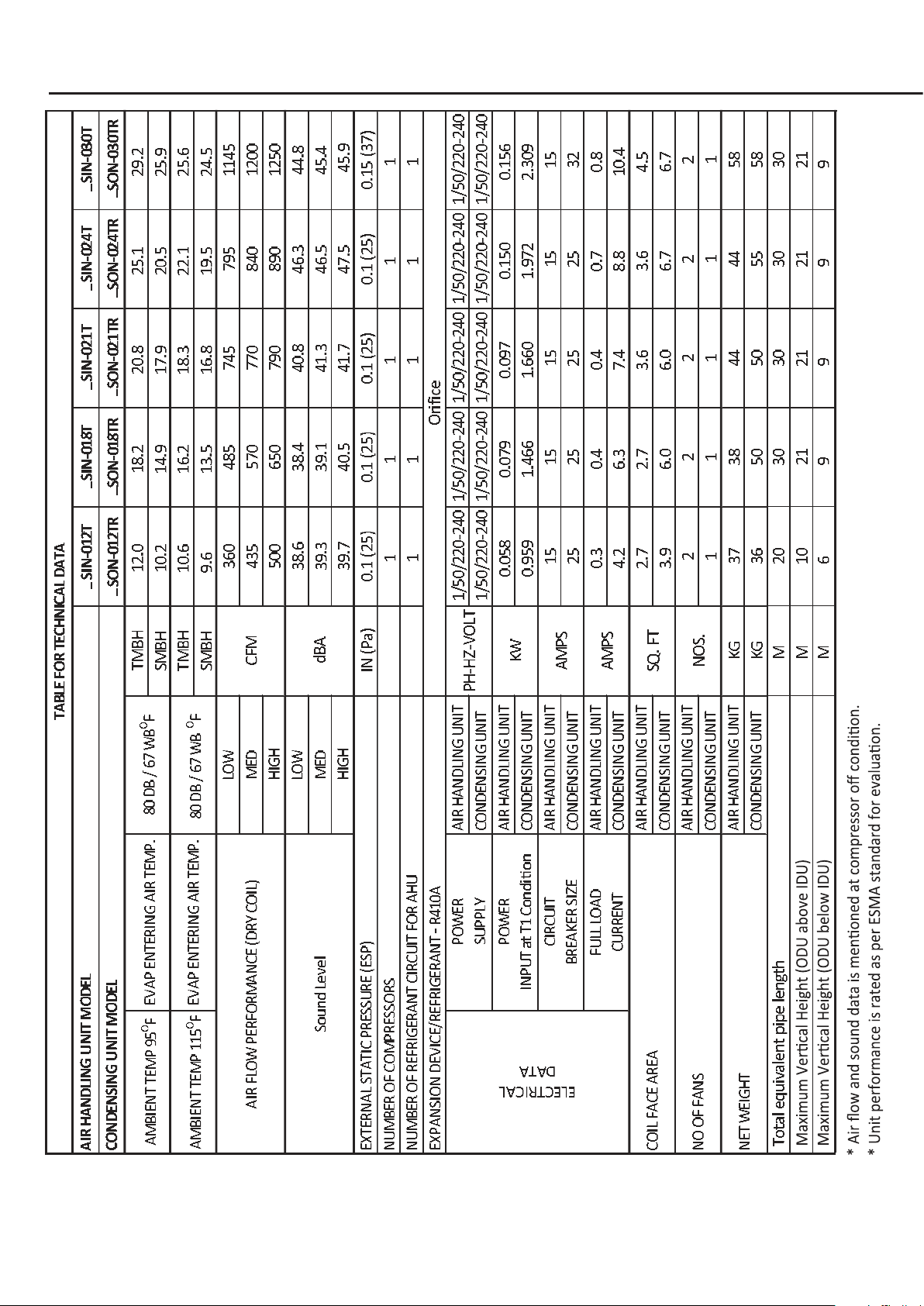
4.1: Technical Specification _SIN - _SON Rotary Units
4.2: Technical Specification _SIN - _SON Scroll Units
4.3: Unit Dimension _SON Rotary Units
4-5
6. 6.0: INSTALLATION INSTRUCTIONS 14-22
3.
2.0: MODEL NOMENCLATURE 6
2.
4.
3.0: GENERAL INFORMATION
7-8
4.0: ELECTRICAL & PHYSICAL DATA ROTARY 9-12
5. 5.0: UNIT DIMENSION _SON SCROLL 13
7. 7.0: REFRIGERANT PIPE CONNECTIONS
7.1: Recommendations
7.2: Line Sizing Chart Rotary
7.3: Suction Line
7.4: Liquid Line
7.5: Minimize Bends
8.1 LEAK TESTING
8.2 VACUUM TEST
9.1: Charging by Weight
9.2: Contamination
10.01 Power Wiring
10.2: Grounding
10.3: Control Wiring
23-26
8. 8.0 LEAK TEST & VACUUM TEST 27
9. 9.0: REFRIGERANT CHARGE 28-29
10. 10.0: ELECTRICAL WIRING 30
11.1: Safety Features
11. 11:0: OPERATION & PERFORMANCE 31
12. 12.0: ELECTRICAL WIRING DIA GRAM 32-34
13. 13.0: TROUBLE SHOOTING 35
14. 12.0: OPERATIONS 36-41
6.1: Corrosive Environment
6.2: Location Unit
6.3: Unit Mounting
6.4: System Operation Information
6.5: Things you may do
6.6: Oil Trap
6.7: Minimize The Equivalent Length
6.8: Pipe Insulation
6.9: Horizontal Runs
6.9: Vertical Runs
6.10 CRANKCASE HEATER (OPTIONAL)
6.11: Pipe Bends
6.12: Pipe bender
6.13 : Copper Elbow
03
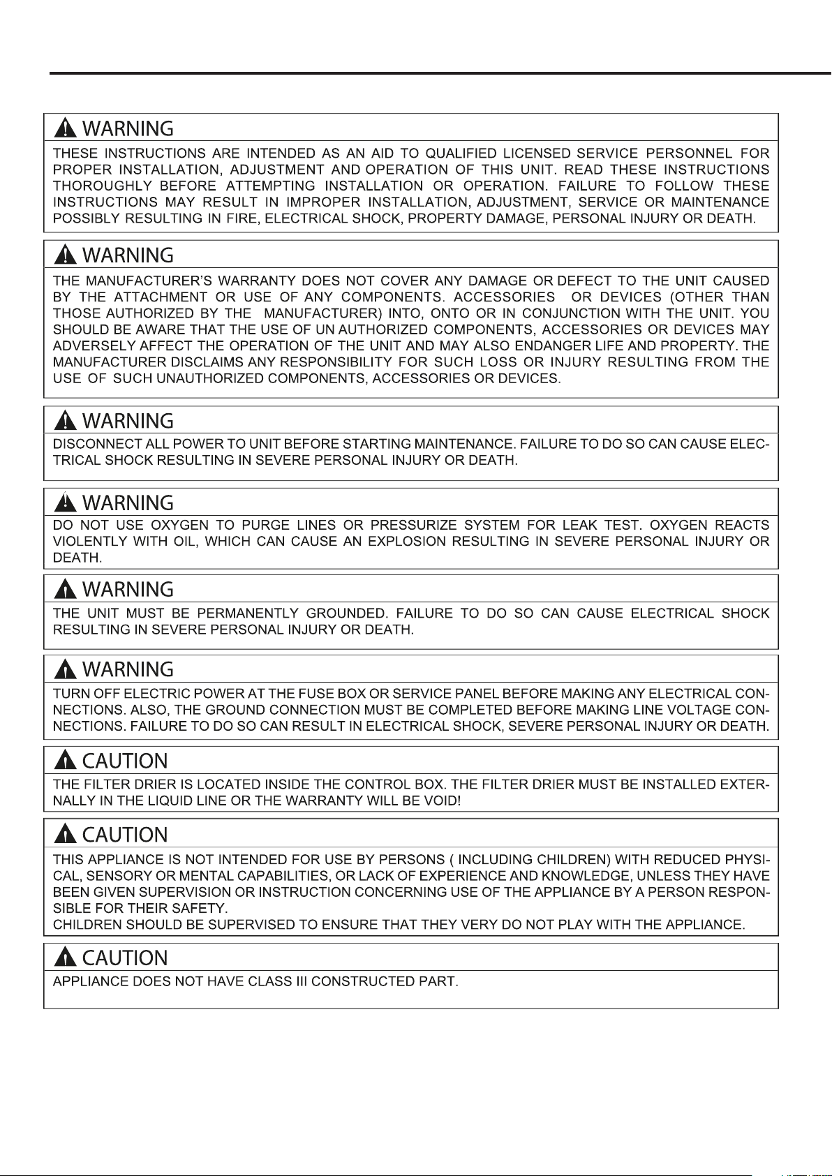
1.0 SAFETY INSTRUCTIONS
1.1 WARNINGS
04

05
Safety precaution
Grounding requirement
1. Must follow the electric safety regulations when installing the unit.
2. According to the local safety regulations, use qualified power supply circuit and air switch.
3. Make sure the power supply matches with the requirement of air conditioner. Unstable power supply or incorrect
wiring or malfunction. Please install proper power supply cables before using the air conditioner.
4. Properly connect the live wire, neutral wire and grounding wire of power socket.
5. Be sure to cut o the power supply before proceeding any work related to electricity and safety.
6. Do not put through the power before finishing installation.
7. If the supply cord is damaged, it must be replaced by the manufacturer, its
service agent or similarly qualified pe_SONs in order to avoid a hazard.
8. The temperature of refrigerant circuit will be high, please keep the interconnection cable away from the copper tube.
9. The appliance shall be installed in accordance with national wiring regulations.
1. The air conditioner is the first class electric appliance. It must be properly grounding with specialized grounding
device by a professional. Please make sure it is always grounded eectively, otherwise it may cause electric shock.
2. The yellow-green wire in air conditioner is grounding wire, which can't be used for other purposes.
3. The grounding resistance should comply with national electric safety regulations.
4. The appliance must be positioned so that the plug is accessible.
5. An all-pole disconnection switch having a contact separation of at least 3mm in
all poles should be connected in fixed wiring.
1.2 Requirements For Electric Connection
06
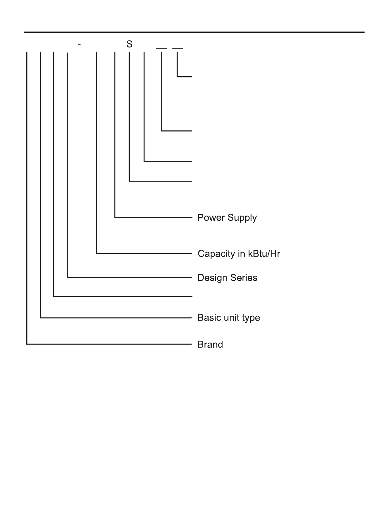
2.0: MODEL NOMENCLATURE
T B X X-
T - 220~240V / 50Hz/1Ph
Optional Features
R - Standard with Rotary Compressor
S - Standard with Scroll Compressor
Optional Blue Fins
Optional
G- Metal Condener Guard
Optional
Q-"State of Qatar" Country code
B-"Kingdom of Bahrain" Country code
K-"State of Kuwait" Country code
O-"Sultanate of Oman "Country code
N - 380~415V / 50Hz/3Ph
x1000
024_ S O N
Outdoor Unit
S - Standard Series

07
- Model Number
- Serial Number
- Country of Origin
- Rated Voltage and Frequency
- Rated T1 and T3 conditions for:
Rated Current
Rated Power (kW)
Rated Capacity
Rated EER
3.1 Checking Product Received
3.2 Application
There are several factors that the installers must consider:
• Outdoor unit location • Proper equipment evacuation
• System refrigerant charge • Indoor unit airflow
• Indoor unit blower speed • Supply and return air duct design and sizing
• System air balancing • Diffuser and return air grille location and sizing
3.0: GENERAL
The information contained in this manual has been prepared to assist in the proper installation,
operation and maintenance of the air conditioning system. Improper installation, or installation
not made in accordance with these instructions, can result in unsatisfactory operation and/or
dangerous conditions, and can cause the related warranty not to apply.
Read this manual and any instructions packaged with separate equipment required to make up the
system prior to installation. Retain this manual for future reference.
To achieve optimum efficiency and capacity, the indoor cooling coils listed in the condensing unit
specification sheet should be used.
IMPORTANT: We recommend replacement of any HVAC equipment that has been subjected to
flooding in order to avoid any risk of injury or harm.
IMPORTANT: Use all available safety precautions during the installation and servicing of any HVAC
equipment.
The Estimated Annual Energy Consumption of this product is calculated using the following formula:
Upon receiving unit, inspect it for any shipping damage. Claims for damage, either apparent or
concealed, should be filed immediately with the shipping company. Check condensing unit
model number, electrical characteristics and accessories to determine if they are correct and
match the original order from the local distributor.Check system components (evaporator coil,
condensing unit, evaporator blower, etc.) to make sure they are properly matched.
Before installing any air conditioning equipment, a duct analysis of the structure and a heat gain
calculation must be made. A heat gain calculation begins by measuring all external surfaces and
openings that gain heat from the surrounding air and quantifying that heat gain. A heat gain calcula-
tion also calculates the extra heat load caused by sunlight and by humidity removal.
Estimated Annual Energy Consumption = Rated Power (kW) at T1 conditions multi plied by 2700
working hours.
Reference the model nameplate and brand label on the unit for the followinig product information:

08
Manifold Sets:
-Up to 800 PSIG High Side
-Up to 250 PSIG Low Side
Manifold Hoses:
-Service Pressure Ratiing of 800 PSIG
Recovery Cylinders:
-400 PSIG Pressure Rating
3.3.1 SPECIFICATION OF R-410A:
Application: R-410A is not a drop-in replacement for R-22 ; equipment designs
must accommodate its higher pressures. It cannot be retrofitted into R-22 condens-
ing units.
Physical Properties:R-410A has an atmospheric boiling point of -62.9°F and its
saturaton pressure at 77°F is 224.5 psig.
Composition: R-410A is an azeotropic mixture of 50% by weight difluoromethane
(HFC-32) and 50% by weight pentafluoroethane (HFC-125).
Pressure: The pressure of R-410A is approximately 60% (1.6 times) greater
than R-22. Recovery and recycle equipment, pumps, hoses and the like need to
have design pressure ratings appropriate for R-410A. Manifold sets need to range
up to 800 psig high-side and 250 psig low-side with a 550 psig low-side retard.
Hoses need to have a service pressure rating of 800 psig. Recovery cylinders need
to have a 400 psig service pressure rating. DOT 4BA400 or DOT BW400.
Combustibility: At pressures above 1 atmosphere, mixture of R-410A and air can
become combustible. R-410A and air should never be mixed in tanks or supply
!CAUTION
R-410A systems operate at higher pressures than R-22 systems. Do not use
R-22 service equipment or components on R-410A equipment.
lines, or be allowed to accumulate in storage tanks . Leak checking should
never be done with a mixture of R-410A and air.Leak checking can be per-
formed safely with nitrogen or a mixture of R-410A and nitrogen.
3.3.2 QUICK REFERENCE GUIDE FOR R-410A
•R-410A refrigerant operates at approximately 60% higher pressure (1.6 times)
than R-22. Ensure that servicing equipment is designed to operate with R-410A.
•R-410A refrigerant cylinders are pink in color.
•R-410A, as with other HFC’s is only compatible with POE oils.
•Vacuum pumps will not remove moisture from oil.
•R-410A systems are to be charged with liquid refrigerants. Prior to March 1999,
R-410A refrigerant cylinders had a dip tube. These cylinders should be kept
upright for equipment charging. Post March 1999 cylinders do not have a dip tube
and should be inverted to ensure liquid charging of the equipment.
• Do not install a suction line filter drier in the liquid line.
•A liquid line filter drier is standard on every unit. Only manufacturer approved liq-
uid line filter driers can be used. These are Sporlan (CW083S) and Alco
(80K083S) driers. These filter driers are rated for minimum working pressure of
600 psig.
•Desiccant (drying agent) must be compatible for POE oils and R-410A.
3.3. Information on R410a & Tools
09
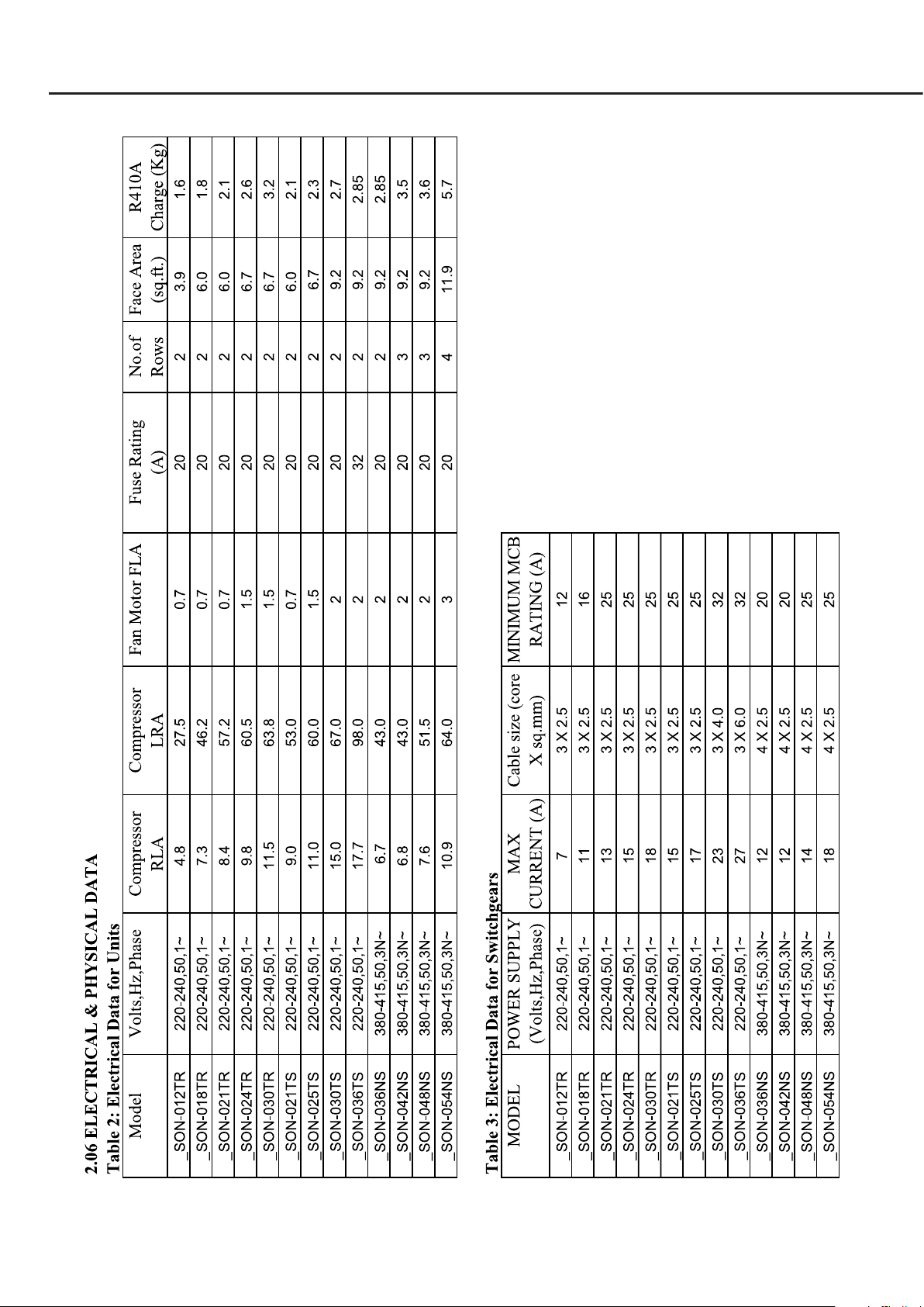
4.0: ELECTRICAL & PHYSICAL DATA _SON ROTARY
10
6
PHYSICAL AND ELECTRICAL DATA
4.1: TECHNICAL SPECIFICATION _SIN - _SON ROTARY UNITS
Table of contents
Other Ruud Heat Pump manuals


Popular Heat Pump manuals by other brands


Mitsubishi Electric
Mitsubishi Electric PUZ-SWM60VAA Service manual

Dimplex
Dimplex LI 16I-TUR Installation and operating instruction

Carrier
Carrier WSHP Open v3 Integration guide

TGM
TGM CTV14CN018A Technical manual

Carrier
Carrier 38MGQ Series installation instructions

Kokido
Kokido K2O K880BX/EU Owner's manual & installation guide

Viessmann
Viessmann VITOCAL 300-G PRO Type BW 2150 Installation and service instructions

Carrier
Carrier 48EZN installation instructions

Viessmann
Viessmann KWT Vitocal 350-G Pro Series Installation and service instructions for contractors

Ariston
Ariston NIMBUS user manual

Weishaupt
Weishaupt WWP L 7 Installation and operating instruction

GE
GE Zoneline AZ85H09EAC datasheet