Data-Linc Group DDAA1000/SRM User manual

USER GUIDE
I
NDUSTRIAL
D
ATA
C
OMMUNICATIONS
It is essential that all instructions contained in the User Guide are followed precisely to ensure proper operation of equipment.
Discrete/Analog Wireless Multiplexer
DDAA1000/SRM

DATA-LINC GROUP
PN161-09981-002C
Product User Guide
FCC Notification
This device complies with part 15 of the FCC rules. Operation is subject to the following conditions:
1) This devicemaynot causeharmfulinterference and
2) This devicemustaccept any interferencereceived,including interferencethat may
causeundesired operation.
The device must be operated as supplied by Data-Linc Group.Any changes or modifications made to the
devicewithout theexpress writtenapproval ofData-Linc Groupmay voidthe user’sauthorityto operatethe
device.
Caution: This device has a maximum transmitted output power of 955 mW. It is required that the
transmit antenna be kept at least 23 cm away from nearby persons to satisfy FCC RF exposure
requirements.
Note: This equipment has been tested and found to comply with the limits for a ClassAdigital device, pursuant
topart 15 of the FCC Rules. These limits are designed to provide reasonable protection againstharmful
interferencein aindustrial installation.This equipmentgenerates, usesand canradiate radiofrequency energy
and, if not installed and used in accordance with the instructions, may cause harmful interference to radio
communications.However, thereis noguarantee thatinterference willnot occur in a particular installation.If
thisequipment doescause harmful interference to radio or television reception, which can be determined by
turning the equipment off and on, the user is encouraged to try to correct the interference by one or more of the
followingmeasures:
Reorientor relocatethereceiving antenna.
Increasethe separation betweentheequipment andreceiver.
Connect the equipment into an outlet on a circuit different from that to which the receiver is connected.
Consultthe dealeror anexperienced radio/TVtechnician for help.
Note: Wheneverany Data-Linc Group SRM series modem is placed inside an enclosure a label must be
placed on the outside of that enclosure which includes the modem’s FCC ID.
Thefollowing antennasareapproved foruse with Data-LincGroup’s 900MHz seriesmodems.
NOTE: Per FCC Rules, the maximum power allowed at the antenna is 4 Watts E.I.R.P.
900MHz Directional Antenna
Gain Manufacturer Manufacture Model Number Data-Linc Model Number
8.2 dBi Larsen YA6900W A-YB
11 dBi Larsen YA5900W A-YHB
900MHz Omni-Directional Antenna
Gain Manufacturer Manufacture Model Number Data-Linc Model Number
5.2 dBi Maxrad MAX9053 A-OB
7.2 dBi Maxrad MAX9075 A-O5B
0 dBi Ying Hao YH920801/AD-725-A-1 A-06/ADJ
0 dBi Centurion EXC-902-BN A-06BH-3S / 10S (**)
(**) This part number refers to an antenna kit(s). The 0 dBi refers to the antenna portion of the kit.
Note: The antenna used for this device must be professionally installed on a fixed-mounted permanent
outdoor structure for satisfying RF exposure requirements, including antenna co-location requirements
of1.1307(b)(3).

DATA-LINC GROUP
1
DDAA1000/SRMUser Guide
PN161-09981-002C
rev 8/04
Table of Contents Page
Introduction 3
Discrete Operation 5
AnalogOperation 8
Changing System or Radio Configurations 12
Technical Specifications 13
Troubleshooting 14
Technical Support 15
ReturnMaterialAuthorization 15
Contact Information 15
AppendixA
Enclosure Dimensions 16
AppendixB
System Configuration 17
AppendixC
RadioConfiguration 21
Main Menu Option (0): Set Operation Mode 23
Main Menu Option (1): Set Baud Rate 25
Main Menu Option (2): Edit Call Book 26
Main Menu Option (3): Edit Radio Transmission Characteristics 28
Main Menu Option (4): Show Radio Statistics 33
Main Menu Option (5): Edit Multi-Point Parameters 35
Main Menu Option (8): Password 38
Modem Placement Locations 39
○○○○○○○○○○○○○○○○○○○○○○○○○○○○
○○○ ○ ○ ○ ○○○○○○○○○○○○○○
○○○○○○○○○○○○○○○○○○○○○○○○○○○○○○○○○○○○○○○○○
○○○○○○○○○○○○○○○○○○○○○○○○○○○○○○○○○○○○○○
○○○○○○○○○○○○○○○○○○○○○○○○○○○○○○○
○○○○○○○○○○○○○○○○○○○○○○○○○○○○○○○○○○○○
○○○○○○○○○○○○○○○○○○○○○○○○○○○○○○○○○○○○○○○○○○○○○○○○○○○
○○○○○○○○○○○○○○○○○○○○○○○○○○○○○○○○○○○○○○○○○○○○○○○
○○○○○○○○○○○○○○○○○○○○○○○○○○○○○○○○○○○○○○○○○○○○○○○○
○○○○○○○○○○○○○○○○○○○○○○○○○○○○○○○○○
○○○○○○○○○○○○○○○○○○○○○○○○○○○○○○○○○○○○○○○○○○○○
○○○○○○○○○○○○○○○○○○○○○○○○○○○○○○○○○○○○○○○○○○○○○○○○○
○○○○○○○○○○○○○○○○○○○○○○○○○○○○○○○○○○○○○○○○○○○○○○○
○○○○○○○○○○○○○○○○○○○○○○○○○○○○○○○○○○○○○○○○○
○○○○○○○○○○○○○○○○○○○○○○○○○○○○○○○○○○○○○○○○○○○○○○
○○○○○○○○○○○○○○○○○○○○○○○○○○○○○○○○○○○○○○○○○○○○○
○○○○○○○○○○○○○○○○○○○○○○○○○○○○○○○○○○○○○○○○○○○○○
○○○ ○○○○○○○○○○○○○○○○○○○○○○○○○○○○○○○○○○○○○○○○○○○
○○○○○○○○○○○○○○○○○○○○○○○○○○○○○○○○
○○○○○○○○○○○○○○○○○○○○○○○○○○○○○○○○○○○○

DATA-LINC GROUP
2PN161-09981-002C
rev 8/04
DDAA1000/SRMUser Guide

DATA-LINC GROUP
3
DDAA1000/SRMUser Guide
PN161-09981-002C
rev 8/04
Introduction
TheDDAA1000/SRM andDD1000/SRMare discrete/analogsignal multiplexers. Theyare designedto provide increased
communication distance where wire lengths are too long or not possible. In general, these units behave as if they replace a
set of wires between the two or more locations. These units are normally factory configured and eliminate the necessity of
having to preset the system configurations. The units are ready for installation into the system upon receipt. If the system
changes, these units do have the capability to be field reconfigured and to have access to the radio setup parameters using
jumper settings and a serial cable to a PC.
Two version of the product exist.The DDAA1000/SRMhas bothanalog anddiscreet inputsand outputs.The DD1000/SRM
has only the discrete inputs and outputs. Discrete (digital) connections and operations are the same for both of the models.
Only the DDAA1000 has 4-20 mA inputs and outputs. Both the DDAA1000/SRM and the DD1000/SRM have distinct
master and remote units. Each system must have one and only one master, and can up to 8 Remotes.
Both the DDAA1000 and the DD1000 take an input at one end and reproduce it at the other end. The Master unit has a
possible total of 8 discrete inputs, 8 discrete relay drive outputs. The Master has eight 4-20 mA inputs and eight 4-20 mA
outputs. When designing a system that use these units, keep in mind that if using more than one remote (8 possible) that
theMaster unit can never have more that 8 digital-in, 8 digital-out,8 analog-in,and 8analog-out.
Communication is accomplished using radio transmissions.Asix inch unity gain whip antenna is supplied with each unit
for test purposes. Note that line of sight is required for communications. In some instances, under 1/2 mile (.80 km), line of
sight may not be necessary. If line of sight does not exist or the units are to be mounted into grounded metal enclosures,
anexternal antenna may be needed. If external antennas were not purchasedwith thisequipment, contactData-Linc Group
forinformation.
Figure 1: DDAA1000 and DD1000
DDAA1000/SRM/M
Power
CD
Status
Pwr
Rx
4-20mA Input 4-20mA Output
Contact Closure Input
Tx
Contact Closure Output
G 1 2 3 4 5 6 7 8G 1 2 3 4 5 6 7 8
8 7 6 5 4 3 2 1 G8 7 6 5 4 3 2 1 G
(425) 882-2206

DATA-LINC GROUP
4PN161-09981-002C
rev 8/04
DDAA1000/SRMUser Guide
Table 1: LED Description
Figure 2: Normal User Connection
DC .dilosnoeblliwDELsihtkniLFRnadehsilbatseevahstinuehtnehW.DELtceteDreirraC
xT .tinugniviecerehtotatadgndnessitinuehtnehwhsalflliW.DELtimsnarT
xR .tinugnittimsnartybtnesgniebatadgniviecernehwsehsalF.DELevieceR
rwP .deilpparewopsahtinunehwdilosnosehsalF.DELrewoP
sutatS nosyatsrosehsalfDEL.ylreporpgnikrowsinoitacinummocnehwffoeblliwDELsutatsehT )ylnotinuretsaM(.stsixemelborpnoitacinummocanehwylidaets
epyTniotcennoCannetnA
epyTdaerhTdaerhTdradnatS
redneGelameF
rotcennoCAMS
rotcennoCrewoP
tsoPfosnoisnemiDmm2
eloHfosnoisnemiDmm5.6
ytiraloPevitisoPniPretneC
egatloVCDV81-5.01,lanimoNCDV21
tnerruCtimsnarTnokaePAm066,eldIAm061
kcolBlanimeT
eziSeriWGWA62-21
Power
Antenna

DATA-LINC GROUP
5
DDAA1000/SRMUser Guide
PN161-09981-002C
rev 8/04
Discrete Operation
Requirements
1. The outputs of the units cannot directly drive a relay. The digital outputs are open collector current sinking to the
common ground.An external power supply must be used to provide DC power to any relays.
2. The maximum voltage on the relay driver outputs is 24 VDC.
3. Ensure that the pull up voltage is sufficient for your relay. i.e. a 12 VDC relay needs 12 VDC, a 24 VDC relay needs 24
VDC.
4. Each digital output can sink up to 100 mA for the purpose of controlling the relay coil.
5. If driving inductive loads, place a voltage suppression diode across the relay coil.
6. There is one common ground for all input and output connections.
Connections
The discrete connection to the device is made via the terminals labeled “Contact Closure Input” and
“Contact Closure Output.” The digital input expects a dry contact, such as a switch or even just a jumper wire.
The output is open collector. The following diagram illustrates the output drive circuit connection for a discrete unit.
Figure 3: Simplified Open Collector
DDAA1000
Output
Output
1,2,3...,8
Common
DC Supply
+ -
Customer
Supplied
Relay

DATA-LINC GROUP
6PN161-09981-002C
rev 8/04
DDAA1000/SRMUser Guide
Point-to-Point Discrete Operation
The following illustrates an example of a point-to-point discrete system. The “Contact Closure Input” may be as simple as a
bare wire or be connected to an output of an I/O module. This is an example of turning a lamp at the Master unit by closing
a contact at the Remote unit using a discrete output.
Point-to-pointdiscrete operations are bi-directional.An input on the Remotewill activatesame numberedoutput onthe
Master.Acontact closure on an input of the Master will close the output on the Remote on the same contact.
Figure 4: Point-to-Point Discrete Operation Example
Contact Closure Input Contact Closure Output
8 7 6 5 4 3 2 1 G8 7 6 5 4 3 2 1 G
Contact Closure Input Contact Closure Output
8 7 6 5 4 3 2 1 G8 7 6 5 4 3 2 1 G
Dry Contact Closure
DC Supply
+ -
Master Remote

DATA-LINC GROUP
7
DDAA1000/SRMUser Guide
PN161-09981-002C
rev 8/04
Point-to-Multipoint Discrete Operation
A multipoint system will involve two or more remote locations, which may be transmitting contact input information,
providingdiscrete outputsor both.The followingis anexample ofa multipointconfiguration.
In this example, the Master is transmitting a contact closure input to both Remotes. Note that input #1 on the Master will
trigger the same numbered output on all Remote units at the same time.
Since there are more remote inputs than master outputs, the contact closures at the Remote inputs are ‘OR’d at the
Masters outputs. The closure of any Remote input will cause the Master output to be On (sinking current). If any Remote
input is closed the Master output will be On for that position. For the Master output to be Off, all Remote inputs must be
open(Off).
Figure 5: Point-to-Multipoint Discrete Operation Example
Contact Closure Input Contact Closure Output
8 7 6 5 4 3 2 1 G8 7 6 5 4 3 2 1 G
Contact Closure Input Contact Closure Output
8 7 6 5 4 3 2 1 G8 7 6 5 4 3 2 1 G
Contact Closure Input Contact Closure Output
8 7 6 5 4 3 2 1 G8 7 6 5 4 3 2 1 G
Dry Contact Closure
DC Supply
+ -
DC Supply
+ -
Master
Remote 0
Remote 1

DATA-LINC GROUP
8PN161-09981-002C
rev 8/04
DDAA1000/SRMUser Guide
Analog Operation
Specifications
1.This unitdoes notprovide looppower todevices.
2. The outputs can operate on loops with a maximum total resistance of 300 ohms.
3. The resolution of this unit is 8 bits with accuracy of 2%.
4.All inputs use a common ground connection labeled “G”.
5. This system is not designed to replace PLCs.
6. It is not recommended to use this product with PLC applications.
7. The input signal must be a 4-20 mA signal.
Point-to-Point Analog System
Theseunits arebi-directional, theysend andreceive analoginformation bothdirections. Thefollowing isa commonexample
of analog use for the DDAA1000/SRM units.Again, the Master’s input corresponds to the same numbered output on the
Remote and vice versa. The 8 Master inputs match the 8 Remote outputs and the 8 Remote inputs match the 8 Master
outputs.
Figure 6: Point-to-Point Analog Example
Pwr
4-20mA Input 4-20mA Output
G 1 2 3 4 5 6 7 8G 1 2 3 4 5 6 7 8
mA
13.7
mA
Sensor
with 4 -20 mA
Output
Pwr
4-20mA Input 4-20mA Output
G 1 2 3 4 5 6 7 8G 1 2 3 4 5 6 7 8
Master Remote
Note:Aloop power supply may be
needed.TheDDAA1000 unitesdonot
supplylooppower.

DATA-LINC GROUP
9
DDAA1000/SRMUser Guide
PN161-09981-002C
rev 8/04
Figure 7: Connection of a flow meter to the DDAA1000/SRM unit
Flow Meter
4-20mA Out In from Sensor
B A
Pwr
4-20mA Input 4-20mA Output
G 1 2 3 4 5 6 7 8G 1 2 3 4 5 6 7 8
12 -24 VDC Supply
+ -
Loop Power
Master or Remote

DATA-LINC GROUP
10 PN161-09981-002C
rev 8/04
DDAA1000/SRMUser Guide
Point-to-Multipoint Analog System
Unlike the discrete versions, the system must be configured for where specific inputs and outputs are directed. Each unit is
normally factory configured and designed to interface with the specific system.Alterations to this configuration are possible
usingan accessorycable andjumpers andsoftware providedby Data-Linc Group. Reconfiguring theunits requiresthe
removal of the cover and uses a custom serial data cable connected to a computer. The reconfiguration of the Master and
Remotesshould normallybeleft toqualified personnel orperformed underData-Linc Group supervision
Factory Configuration Process
At the factory, each remote unit is given an address, which is zero (0) to seven (7). Each unit is then programmed for a
specific number of analog inputs and outputs, which should to be predetermined prior to sale.Also consider if the system is
to be expended in the future. Note that any system will have one Master and a maximum of 8 Remotes.
Limitations of the Configuration Process
Each master unit has eight analog inputs and eight analog outputs. These inputs and outputs can be spent in a variety of
ways when configuring a multipoint system. Note that with analog operation, each remote unit’s input corresponds with a
specific master output. Two remote units cannot share the same inputs and outputs as with the discrete section. The
following is a sample diagram of a point to multipoint configuration.

DATA-LINC GROUP
11
DDAA1000/SRMUser Guide
PN161-09981-002C
rev 8/04
Point-to-Multipoint Analog Operation
Asystem is to be built where one analog input exist at one remote and one at another. The maximum possibility of master
outputs is eight, so this is a valid configuration. Remote 0 being the first remote in the Master’s poll list will be assigned
Master output one. Remote 1 being next in the poll list will be Master output two.
Figure 8: Point-to-Multipoint Analog Example
Pwr
4-20mA Input 4-20mA Output
G 1 2 3 4 5 6 7 8G 1 2 3 4 5 6 7 8
Pwr
4-20mA Input 4-20mA Output
G 1 2 3 4 5 6 7 8G 1 2 3 4 5 6 7 8
mA
13.7 mA
Sensor
with 4 -20 mA
Output
Pwr
4-20mA Input 4-20mA Output
G 1 2 3 4 5 6 7 8G 1 2 3 4 5 6 7 8
Sensor
with 4 -20 mA
Output
Output from Remote 0
Output from Remote 1
Master
Remote 0
Remote 1
Note:Aloop power supply may be
needed.TheDDAA1000 unitesdonot
supplylooppower.
Note:Aloop power supply may be
needed.TheDDAA1000 unitesdonot
supplylooppower.
*** Systems with only one
analoginput on eachremote

DATA-LINC GROUP
12 PN161-09981-002C
rev 8/04
DDAA1000/SRMUser Guide
Changing System or Radio Configurations
To access the system or radio setups the user must remove all connectors from the DDAA1000/SRM or DD1000/SRM,
then remove the cover and change the jumpers at location P1 and P2, and add a serial data cable (SRM6200E-SLC),
supplied by Data-Linc Group, to connector P3. These jumper settings must be returned to the RUN/RF settings after
reconfiguring the system or the radio or the units will not operate. See layout drawing.
Thereare 4configurations of the jumpers.
1. RUN / RF NormalDDAA/1000 andDD1000/SRMoperations
2. CONFIG /RF Serial port P3 to PC (computer) to access the radio parameters
3.CONFIG /PIC Toreprogram the system configuration setup memory
4.RUN /EXT Factory use only - do not use
If changing the system configuration go toAppendix B.
Ifchanging theradio parametersgo toAppendix C.
Figure 9: Layout Drawing

DATA-LINC GROUP
13
DDAA1000/SRMUser Guide
PN161-09981-002C
rev 8/04
Technical Specifications
Channels
DD1000/SRM has 8 discrete inputs and 8 discrete outputs.
DDAA1000/SRM has 8 discrete inputs, 8 discrete outputs, 8 analog inputs and 8 analog outputs.
Channel Specifications
Analog: 2% accuracy or better with a maximum output load of 300 ohms.
Discrete: Open collector outputs which can handle up to 24V and can sink up to 100 mA for controlling relay coil.
Temperature
32oto140o F (0o to 60oC)
Power
10.5 - 18 VDC. Maximum current draw is 660 mA.
RF Specifications
Spreadspectrum frequency hopping
Modulation:GFSK
FrequencyRange: 902-928 MHz
ChannelSpacing: 230.4 kHz
ErrorDetection: 32 bit CRC
OperatingMode: ClassA
Methodof Tuning:Digital Synthesizer
RF Power: 1 Watt
ReceiverSensitivity: -110dBm

DATA-LINC GROUP
14 PN161-09981-002C
rev 8/04
DDAA1000/SRMUser Guide
Troubleshooting
I have the units setup on a bench for testing, but the Master’s status LED keeps flashing or is solid and I do
not have a carrier.
When shipped, the units are setup for a maximum transmit power of 1 watt. If there are only a couple feet of separation
between them, the supplied whip antenna may need to be removed. Note that this will not damage the unit.
The units are installed in the field, but I have a flashing or solid LED on the status and no carrier.
The Master’s status LED only comes on when a responce from a remote is not obtained after 3 tries, then the Master
moves on to the next Remote.A solid light indicates that the Master can not connect to any remotes. A blinking light
indicates that the Master has lost communication with at least one remote. Most likely problem is a radio line-of-sight
problem exists If external antennas are being used, verify that they are grounded and that line of sight exists.Also verify
that the input power is OK.AUPS is recommended in areas where clean power may not exist. If units are bench
tested, and ther is no communications, then you may have a mis-configured system. If the system has been working
andthen fails, check for cable and antennaconnections, andDC powerlevels.
The power LED on one or both of my units is out and I have no communication.
Try cycling power on either of the units, the resettable fuse may have tripped. If communications do not come up again,
verifythat there is power to the device. The supplied wall transformer output is nominally around18 VDCwhen theradio
is not transmitting, and drops to 12 VDC when the transmitter is on. If the supply is okay and cycling power does not
fix the problem, contact Data-Linc Group.
My analog output reads 4 mA all the time.
Verify that the connection of the transducer at the transmitter is okay. Put a milliamp meter in the loop, and verify that
the connected transducer is supplying more than 4 mAinto the unit. Verify that the correct current polarity is used.
Note that Data-Linc Group unit does not supply loop power.
My analog output is 0 or below 4 mA.
ContactData-Linc Group.The analogoutput hasfailed. This is a hardwareproblem.
The discrete output will not activate my relay.
The discrete output of the DDAA1000 or DD1000 does not supply power for a relay coil. Refer to the open collector
diagramfor connections.
My relay switches on and off constantly.
Verify that the Master’s status LED does not light. The status LED refers to loss of RF communication data stream.
Make sure the relay coil does not require more than 100 mA. The discrete outputs can only sink 100 mA.
The relay never switches.
Verify that the switch on the input side is wired properly to the DDAA1000 or DD1000. Check the discrete output with a
multimeter. Set the meter for continuity and place the “+” lead on the “G” or common terminal and “-” on the correct
discrete output.

DATA-LINC GROUP
15
DDAA1000/SRMUser Guide
PN161-09981-002C
rev 8/04
Technical Support
Data-LincGroup maintains afullytrained staff ofservice personnel whoarecapable of providingcompleteproduct
assistance.They canprovide you withtechnical, applicationand troubleshooting,spare parts andwarranty assistance.
Ourtechnical staffis based inBellevue, WashingtonUSA and maybe reachedat (425) 882-2206or e-mail
Product Warranty
Data-LincGroup warrants equipmentof its ownmanufacture to befree from defectsin material andworkmanship for one
yearfrom date of shipment to original user.Data-LincGroup willreplace orrepair, atour option,any partfound to be
defective.Buyer must returnany part claimeddefectiveto Data-LincGroup,transportation prepaid.
Return Material Authorization
If a part needs to be sent to the factory for repair, contact Data-Linc Group’s corporate office and request a Return Material
Authorization(RMA) number.The RMAnumberidentifies the partandthe ownerand must beincluded withthe partwhen
shipped to the factory.
Contact Information
Corporate Office Data-Linc Group
3535Factoria Blvd.SE
Suite100
Bellevue,Washington98006 USA
Telephone:(425)882-2206
Fax:(425)867-0865
E-mail:[email protected]
Website: www.data-linc.com

DATA-LINC GROUP
16 PN161-09981-002C
rev 8/04
DDAA1000/SRMUser Guide
Appendix A
EnclosureDimensions
TOP
4 - 20mA OUTPUT
PWR
STATUS
CONTACT CLOSURE INPUT
8 7 6 5 4 3 2 1 G
CONTACT CLOSURE OUTPUT
8 7 6 5 4 3 2 1 G
4 - 20mA INPUT
DATA-LINC GROUP
(425) 882-2206
DDAA1000/SRM/M
Rx
CD
Tx
6.85
G 1 2 3 4 5 6 7 8 G 1 2 3 4 5 6 7 8
POWER
5.655
4.065 3.935 4.80
approx
SIDE
Ø 0.19
3.18
6.35
1.80
1.725 1.65

DATA-LINC GROUP
17
DDAA1000/SRMUser Guide
PN161-09981-002C
rev 8/04
Appendix B
Figure 10: PCB Layout
DDAA1000 - DD1000 Configuration
The system configuration parameters are stored in an EEprom memory. This memory can only be changed by the onboard
microprocessorusing serialcommands via port P3. The easiest method is to use the Data-Linc Group program provided
with the master unit, to be run on a PC. If the program is missing contact Data-Linc GroupTechnical Support.
A DDAA1000/DD1000 system is normally factory pre-configured. Changes to the system are possible, but it is
recommendedthat theuser performthis functionunder directionof Data-LincGroupTechnical Support personnel. If the
utility program is missing, it is possible to change the setting using a PC with a terminal program, but Data-Linc Group help
must be used as the system setting can be confusing.An internal knowledge of the microprocessor operation is vital to
understand how to set the system memory. Setting any of the system configuration parameters wrong will make a broken
system.
To accessthe systemconfigurations theuser mustremove all connectors from the DDAA1000/DD1000, the remove the
cover, and change a set of jumpers atlocation P1and P2and adda serialdata cable (SRM6200E-SLC) available from
Data-Linc Group to connector P3. See Figure 10, PCB layout drawing. Use the CONFIG-PIC layout as shown on the PCB
drawing.
To change the system configuration, set the P1 and P2 jumpers as shown on the layout drawing. Use the CONFIG-RF
layout as shown on the PCB drawing. The dark lines represent the three small jumpers. Then insert the Data-Linc Group
serial cable into connector P3 located next to the power connector.Attach the serial cable to a PC.
Rememberthat thereare twodifferentpart numbers for Masters and Remotes.They containdifferentfirmware.AMaster
cannot be made into a Remote, and a Remote cannot be made into a Master. However, either a Master or Remote can
havethe abilityto reprograman EEpromfrom either a Master orRemote. Thisinvolves removingand replacingthe EEprom
(U3) on the PCB. Not recommended for most users.

DATA-LINC GROUP
18 PN161-09981-002C
rev 8/04
DDAA1000/SRMUser Guide
If you have the Data-Linc Group PC program DDAAEEprom.exe it is designed to run in Windows. Load the program
DDAAEEprom.exe into your PC. Start the program. When the system layout window appears fill in the following
information:
1. Select Model DDAA or DD1000 with mouse click.
2. The PCs Comm (serial port) number 1 or 2 with a mouse click.
3. The serial Baud rate that the DDAA1000/DD1000 uses to talk to the radio module. This is not the connection speed to
the computer. This must match the Baud rate set in the radio module.The factory default for the radio module is 9600.
4. Select System Configuration as either a Point-to-Point (one remote) or a Multipoint system (more than one remote) with
mouse click.
5. Select this unit is a Master or a Remote. This must agree with the code in the microprocessor. You can not change a
units Master/Remote type in the field.
6. The number of remotes if a Multipoint System.
7.If programminga MultipointRemote selectRemote IDor addressyou arechanging. Remoteshave addressesof zero(0)
toseven(7).
If the unit is a DD1000 click on the “Make an EEprom” button and follow the prompting instructions on the screen. . If any
previous setting are in conflict or you have not made a needed selection, the parameter will highlight to red. To proceed,
correctly fill in the parameter and click the “Make an EEprom” again.
The program will write several characters into the boxes at the bottom, and lower left of the display. These are the serial
commandscontaining the system parameters that are sent and receivedby theDDAA1000/DD1000 units.
Repeat this procedure once for each Master, and once for each Remote in the system. Make sure you change the address
foreach Remote.
Each time the program finished making an EEprom, and if a printer is connected to the computer, you can click on the
PRINT button on the lower right corner to make a record of the system configuration. It will be handy later when you call
Data-Linc Group to try to figure out why your system won’t work.
When done, click on the EXIT button at the lower right corner of the window.
If the unit is a DDAA1000,fill in the Master DDAA chart. The ‘X’s in the chart are the system configuration. The Remotes
ID is the left side of the chart, the IN columns are the 4-20ma input numbers on the Masters connectors.Assign analog
input(s) to each Remote by clicking the cursor on the row (address) and column (input #) for the Remote and the input to
use. This will toggle the ‘X’on or off.Assign the analogs for Remote zero (0) first, then Remote one (1), Remote two (2) thru
seven (7). If there are less than seven remotes toggle the remaining ‘X’s off. The default for the system is all 8 analog inputs
assigned to Remote zero( 0).
The program will not allow the user to assign analog inputs in a wrong order. If a wrong assignment is made then program
removes the ‘X’ selection. The maximum number of rows used is set by the number of remotes selected in step 6 above.
Do not leave any columns blank if a later column has an ‘X’. The data transfer from Master to Remote will stop when a
blank filed is reached. Blank columns at the right side of the table are okay. Not all analog inputs need to be assigned, just
noorphaned –emptycolumns.
This manual suits for next models
1
Table of contents
Popular Multiplexer manuals by other brands
Lynx
Lynx P MX 3214 B Reference manual
East Coast Datacom
East Coast Datacom Nx8- Dual Composite MUX High-Speed 16-Port TDM... Operation manual

Alcatel-Lucent
Alcatel-Lucent 1643 AMS brochure

Datacom
Datacom DM16E1 Installation and operation manual
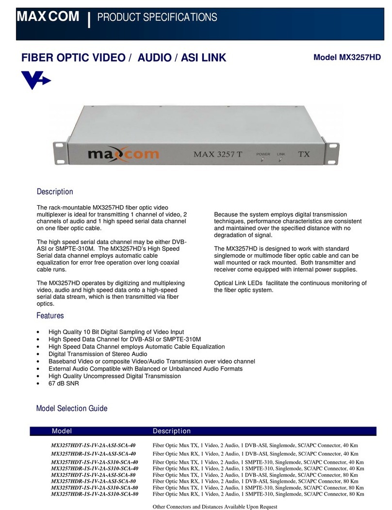
Maxcom
Maxcom MX3257HD Product specifications

Keithley
Keithley 7074 instruction manual
