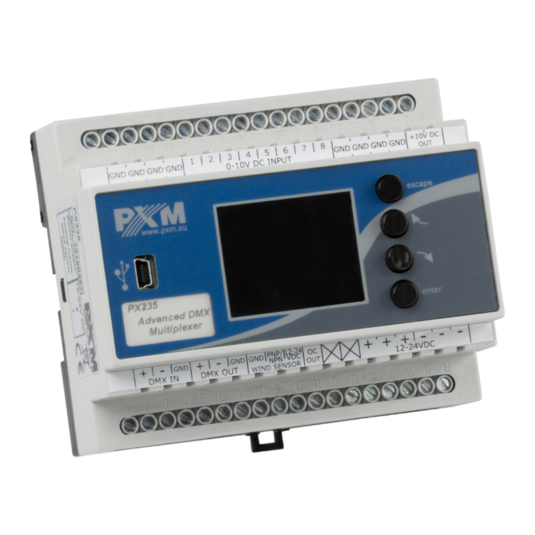
PXM PX235 User manual

MANUAL
PX 235
Advanced DMX
Multiplexer
R

CONTENTS
1
1
2
2
3
3
4
4
5
5
6
7
8
8
8
9
10
10
11
1. General description.............................................................................................................
2. Safety conditions.................................................................................................................
3. Description of the connectors and control elements...........................................................
4. Navigating the menu...........................................................................................................
5. Summary screen.................................................................................................................
6. Main Menu..........................................................................................................................
7. Programming the device functions......................................................................................
7.1. DMX Out Settings..............................................................................................
7.2. Firmware Info.....................................................................................................
7.3. Analog input > DMX...........................................................................................
7.4. Wind speed > DMX............................................................................................
7.5. DMX Patching....................................................................................................
7.6. Counter input settings........................................................................................
7.7. Alert output.........................................................................................................
7.8. Language Settings.............................................................................................
8. Connections diagram..........................................................................................................
9. Dimensions.........................................................................................................................
10. Technical Data...................................................................................................................
11. Declaration of conformity...................................................................................................
Manufacturer reserves the right to make modifications in order to improve device operation.
Rev.1.2.
PXM Marek Żupnik spółka komandytowa
ul. Przemysłowa 12
30-701 Kraków
POLAND
tel.: (+48 12) 626 46 92
fax: (+48 12) 626 46 94
E-mail: [email protected]
Internet: www.pxm.pl

1
1. GENERAL DESCRIPTION
2. SAFETY CONDITIONS
Advanced DMX Multiplexer PX235 is powered with safe voltage 12 - 24V; however, during
its installation and use the following rules must be strictly observed:
1. The device may only be connected to 12 - 24V DC current (stabilized voltage) with
current-carrying capacity compatible with technical data.
2. All the conductors should be protected against mechanical and thermal damage.
3. In the event of any conductor damaging, it should be replaced with the one of the same
technical data and attestations.
4. Connection of DMX signal should be made with shielded conductor.
5. All repairs and connections of outputs or DMX signal can only be made with power off.
6. PX235 should be strictly protected against contact with water and other liquids.
7. All sudden shocks - particularly dropping - should be avoided.
8. The device cannot be turned on in places with humidity exceeding 90%.
9. The device cannot be used in places with temperature lower than +2°C or higher than
+40°C.
10. For cleaning use only a damp cloth.
Advanced DMX Multiplexer is a complex device that allows to change analog signal 0-
10V to the DMX-512 signal. Analog signal is converted into a digital signal and then it is
inserted or replaced at the appropriate (chosen by the user) DMX channel from the DMX-
512 package.
It has eight inputs parametrized as a 0-10V analog or digital (active with low or high
state). In case of choosing replacing of DMX channels by the converted analog signal, the
last channel DMX-512 package are cut to make room for the added channels (their number
depends on the number of analog inputs are connected).
The PX235 has built-in one input and output of DMX signal. Color display provides a
graphical representation of information about the state of the signal and thus its' control.
Pulse input allows to cooperate with the PNP and NPN signals (e.g. wind sensors
connected - anemometer). Signal parameters and the current value are displayed on the
display screen. The USB connector allows communication with a computer and simplifies
update firmware installed on the PX235.
Built-in OC output (Open Collector) allows you to configure and then signaling the set
of states in the form of alarms. The device also has a 10V output that can power analog
sensors such as potentiometers and photometers.
Starting from Px235 serial number: 13091243. a new firmware 2.0 has been
introduced. It may only be used with PC software version 2.0 or higher.

2
3. DESCRIPTION OF THE CONNECTORS AND CONTROL ELEMENTS
4. NAVIGATING THE MENU
321
V+
4
5
6
1DMX-512 Input
2
Power supply
3
DMX-512 Output
4LCD Screen
5Control outputs
6Control buttons
Navigating the menu allow programmable buttons. Every button is
described on the right side and their use is as follows:
- allows to enter the selected option and approve set value
- scrolls up the menu or right (horizontal menu)
- scrolls back the menu or left (horizontal menu)
- exits from the currently programmed parameter without
saving the changes or goes to the level in the menu above
(pressing the button while being in main menu will
cause to exit to the summary screen)
escape
To change the value of selected parameter, you must choose on the screen
button or using the button or , and then using the button to
change the value.
After that you need to save the settings before going level up, this will allow
storing value in memory of the PX235. To do this, after moving to the screen button
you need to push enter button.
+ – next previous enter
7
7USB input
80-10V Inputs
8

3
6. MAIN MENU
At the top of the screen is a bar to choose between a 3 screens of the main
menu. To go to the other two please select the > button by pressing or ,
and then confirm the selection of the enter key. The first screen shown after hitting the
button is the . Another is the . Both represent in graphic form the current
state of input and output signal from the device.
Summary
Previous Next
DMX In DMX out
5. SUMMARY SCREEN
When you turn the device appears on the screen panel, which describes the
current state of DMX signal. If the device takes the DMX signal is green displays
.
In case of no DMX signal detected at the input to the device on the screen will
be showed message .
DMX
Signal OK
No DMX Signal
Description of the other messages on the Summary screen:
! - Current wind speed from the anemometer and its
value after conversion to the DMX protocol (value of this function can be changed in a
Menu Wind Speed > DMX)
! - information regarding the status of alarm output: red dot indicates the
output off and the green output on.
! ...- voltage value in the subsequent analog inputs 0-10V and the
value in DMX protocol of assigned to them DMX channels.
Speed 0.00 [m/s] -> DMX: 000
Out OFF/ON
1: 00.00[V]>000,

The presentation of the DMX signal:
The value of DMX signal to the frame (DMX channel) is portrayed as a white
column, whose height varies proportionally according to the formula: the highest =
largest value of DMX signal - 255, no column = no DMX signal, value is 0.
Number of frame (DMX channel) is described on the left, respectively: 1, 129,
257, 385 for subsequent lines. In addition, each line is divided into parts, where red dots
means another ten channels, and green ones the next 100 channels.
After selecting a submenu on the screen show up currently
set parameters of the DMX signal. Default values set on the device are visible below.
DMX Out Settings
7. PROGRAMMING THE DEVICE FUNCTIONS
On the top of each of the main screens is the button. After the selection of which,
from each of the three screens, the user will be moved to the menu screen, which allows
to set all the functions of the device.
Menu
4
7.1. DMX Out Settings
At the bottom of the screen is displayed the aggregate and
for so configured parameters.
Packet length Refresh rate

1.Break Time allows to change the length of the interval between successive DMX
packets. Break signal may take longer, but can not be less than 120 microseconds.
Usually it lasts about 120-140 microseconds.
2. MAB Time (Mark after break) is the interval time that occurs in each package
according to the standard DMX-512. The PX235 allows minimum value of 16
microseconds.
3. MBF (Mark Between Frame) -
frame (end of the 2nd stop bit) and the start of the next - Mark Time Between Frames
(MTBF) is the full name. Its length can range from 0 to 1000 microseconds, the shorter
the better.
4. Packet gap - the amount of time between packets. Its length can range from 16 to
5000 microseconds.
5. Channels number - Using this feature, you can limit the number of channels sent
from the PX235. The minimum value is 24 channels and the maximum is 512 (default).
the amount of time (if any)between the end of one
5
At the top of the screen next to
the option name are visible
important information that
simplify setting an appropriate
value. To save the value before
leaving level up in menu You
need to select floppy disc
button and press .enter
Remember to save values by
selecting the button
and pressing enter

In this submenu you can check the firmware installed on the device. You can
also restore the default settings implemented on the device.
6
7.2. FIRMWARE INFO
To do this push , then select the button and again approve with enter.
In the case of incorrect choosing this option, you can go back by selecting , or go
directly level up in menu by pressing escape.
enter Yes
No
7.3. ANALAOG INPUT > DMX
This option allows you to set up conversion voltage of the analog inputs onto
the DMX signal. Thus allows the selection characteristic conversion.
(Default) Setting the value (A) 0 [V] and values (B) at 10 [V] allows to obtain linear
proportional operating characteristic.
Changing to opposite values of the A and B allows to get reverse operating
characteristic. To set the value You need to select the Set button, and then proceed as
described in Section 4 on page 2 to change the parameter value and save it. Each input
can have distinct characteristics of the signal conversion.
To change operating characteristic of each input You need to select buttons or on
the screen in right bottom corner and using the enter key set the number of currently
modified input.
Remember to save values by
selecting the button
and pressing enter

7
7.4. WIND SPEED > DMX
7.5. DMX PATCHING
Wind speed onto the DMX is a function that allows you to set parameters of conversion
of the voltage signal from the anemometers to values compatible with DMX protocol. To
set the limit values You need to approve with the enter the set button on the screen and
follow the point 4 on page 2. Changes made to the settings are shown graphically in the
chart.
DMX Patching allows to assign the subsequent channels of DMX512 package output
value from both DMX inputs, as well as analog and counter input. It is also possible to
set each channel to a constant value of 0 or 255 (default channels 511 and 512 are set to
0 and 255).
A parameter in the default
settings is 0. B parameter
value is 50.
Remember to save values in
menu by selecting the
button and pressing
set
enter
In order to assign a output DMX channel with a different input parameter you should
choose that one, on which we want to make changes and press the key. Then
using or buttons set the new value and confirm with
enter
next previous enter.

8
7.6. COUNTER INPUT SETTINGS
7.7. ALERT OUTPUT
Counting Input Settings menu allows to change some values and the characteristic
parameter of the anemometer (Transducer output) of formula 1 [Hz] = x [m / s].
The default is set to 0.1 [m / s], but be sure to check this parameter and (if needed) to
change after connection of the new anemometer.
Another option you can set is the counting input configuration. Sometimes there is need
to change the type of electric signal amplifying transistor (PNP or NPN) dependent on
the anemometers (or if both types of method connecting to the device are used).
To change the type select the field and confirm with .polarization enter
Alarm output allows the individual set the parameters on and off the alarm output. Time
On Set determines how many seconds takes to turn on the alarm, during which the wind
speed exceeds a threshold alarm. Time Off Set is the time after which the alarm turns
off, the alarm status changes if wind speed decreases below the predetermined
threshold.
Remember to save values in
menu by selecting the
button and pressing
set
enter
Remember to save values in
menu by selecting the
button and pressing
set
enter

Language Settings
previous next enter
allows you to change the menu language. To do this select
appropriate language with or buttons and press .
7.8. LANGUAGE SETTINGS
8. CONNECTIONS DIAGRAM
9
anemometer
power supply
12-24 V DC
np. DR-15-12
LN
DC OK
CW CW CW CW
POTENTIOMETERS
+10V OUT
GND
0 - 10V IN
0 - 10V IN
0 - 10V IN
0 - 10V IN
a) CONNECTION TO POTENTIOMETERS
GND
PNP/NPN
12-24 VDC

GND
0 - 10V IN
0 - 10V IN
0 - 10V IN
0 - 10V IN
0 - 10V SINGAL SOURCES
b) 0 - 10V control
power supply
12-24 V DC
np. DR-15-12
LN
DC OK
0,5A max load
9. DMX SIGNAL CONNECTION
GOOD WRONG
DMX-512 Input DMX-512 Output DMX cable
Caution!
Do not connect DMX input and
output pins parallel.
See paragraph 9 of the manual.
DMX-512 Input DMX-512 Output
Do not overload the output
OC OUT
12
PX235 must be connected to the DMX line in series. This means that a cable should
be connected to the DMX IN terminal, and then from the DMX OUT terminal the
cable should go to other DMX receivers.

12 - 24V DC
1
1
8
1 (to power supply ex. potentiometers)
1
Clamping screws, USB
0,2kg
Width: 105mm
Height: 85mm
Deepth: 60mm
- Power Supply
- DMX Input
- DMX Output
- 0-10V Inputs
- 10V Output
- OC Type Output
- Connectors
- Weight
- Dimensions:
11. TECHNICAL DATA
10
10. DIMENSIONS
105 mm
85 mm
60 mm

PXM Marek Żupnik sp. k.
PN-EN 61000-6-1:2008
PN-EN 61000-6-3:2008
ul. Przemysłowa 12
30-701 Kraków, POLAND
PX235
All DMX512 inputs and outputs must be shielded
and the shielding must be connected to the ground
responding to the DMX connectors.
mgr inż. Marek Żupnik.
Advanced DMX Multiplexer
Name of producer:
Address of producer:
declares that the product:
Name of product:
Type:
answers the following product specifications:
EMC:
Additional informations:
Kraków, 03.02.2011
DECLARATION OF CONFORMITY
according to guide lines 2004/108/EC
14
tel: +48 12 626 46 92
fax: +48 12 626 46 94
e-mail: [email protected]
http://www.pxm.pl
ul. Przemysłowa 12
30-701 Kraków, Poland
stage and theatre consoles digital dimmers dmx systems architectural lighting controllers led lighting
Other manuals for PX235
1
Table of contents
Other PXM Multiplexer manuals
Popular Multiplexer manuals by other brands

Pickering
Pickering 40-658 user manual

Comnet
Comnet Value FVR81 Series Installation and operation manual

Ultra electronics
Ultra electronics MX420-OP2 installation instructions

oxic
oxic XFO1013TS user manual

CTC Union
CTC Union ERM-MUX/PLUS Operation manual

ShipModul
ShipModul MiniPlex-3 Series Firmware Guide

Cisco
Cisco 6160 Installation procedures

Black Box
Black Box Local Mux-6 user manual

Agilent Technologies
Agilent Technologies 34921A user guide

OCENAV
OCENAV ATM 105-A3 Quick installation guide

Feig Electronic
Feig Electronic OBID i-scan ID ISC.ANT.MUX Installation

Giga-tronics
Giga-tronics 3000-08 90400490-100 Operation manual