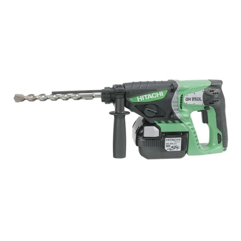
Datacol L210116 User manual

1
9
7
6
Variable speed
L210116
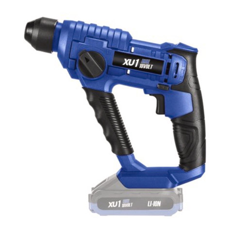
Cordless Rotary Hammer
Martello perforatore a batteria
1
Read through carefully and understand these instructions before use.
Prima dell’uso leggere attentamente e comprendere queste instruzioni.
605
Code No. C99152941 N
Printed in Japan
Handling instructions
Instruzioni per l’uso
1 2
4
6
8
3
5
7
7
65
A
0BC
D
H
3
4
8
0AC
G
F
I
E
1
2
K
J
English
EC DECLARATION OF CONFORMITY
We declare under our sole responsibility that this
product is in conformity with standards or standardized
documents EN50144 and EN55014-2 in accordance with
Council Directives 89/336/EEC and 98/37/EC.
This declaration is applicable to the product affixed CE
marking.
Representative office in Europe
Hitachi Fercad Power Tools Italia S.p.A.
Via Retrone 49-36077, Altavilla Vicentina (VI), Italy
Declared by
Hitachi Koki Co., Ltd.
Shinagawa Intercity Tower A, 15-1, Konan 2-chome,
Minato-ku, Tokyo, Japan
31. 5. 2006
K. Kato
Board Director
Italiano
DICHIARAZIONE DI CONFORMITÀ CE
Si dichiara sotto nostra responsabilità che questo
prodotto è conforme agli standard o ai documenti
standardizzati EN50144 e EN55014-2 conforme alle
direttive 89/336/CEE e 98/37/CE del concilio.
Questa dichiarazione è applicabile ai prodotti cui sono
applicati i marchi CE.
Datacol S.r.L.
Strada Statale 11, Z.A.I.
37047 San Bonifacio (VR), Italy

1
9
7
6
Variable speed
L210116
Cordless Rotary Hammer
Martello perforatore a batteria
1
Read through carefully and understand these instructions before use.
Prima dell’uso leggere attentamente e comprendere queste instruzioni.
605
Code No. C99152941 N
Printed in Japan
Handling instructions
Instruzioni per l’uso
1 2
4
6
8
3
5
7
7
65
A
0BC
D
H
3
4
8
0AC
G
F
I
E
1
2
K
J
English
EC DECLARATION OF CONFORMITY
We declare under our sole responsibility that this
product is in conformity with standards or standardized
documents EN50144 and EN55014-2 in accordance with
Council Directives 89/336/EEC and 98/37/EC.
This declaration is applicable to the product affixed CE
marking.
Representative office in Europe
Hitachi Fercad Power Tools Italia S.p.A.
Via Retrone 49-36077, Altavilla Vicentina (VI), Italy
Declared by
Hitachi Koki Co., Ltd.
Shinagawa Intercity Tower A, 15-1, Konan 2-chome,
Minato-ku, Tokyo, Japan
31. 5. 2006
K. Kato
Board Director
Italiano
DICHIARAZIONE DI CONFORMITÀ CE
Si dichiara sotto nostra responsabilità che questo
prodotto è conforme agli standard o ai documenti
standardizzati EN50144 e EN55014-2 conforme alle
direttive 89/336/CEE e 98/37/CE del concilio.
Questa dichiarazione è applicabile ai prodotti cui sono
applicati i marchi CE.
Datacol S.r.L.
Strada Statale 11, Z.A.I.
37047 San Bonifacio (VR), Italy

23
910
12
11
15
14
13
16
L
Z
[
d
28
[ ]U
PQ
TS
L
(a)M(b)N(c)O
L
R
W
V
AB
X
Y
\
B
C
=]
B
C
]
`
a
b
19
18
17
20
e
i
f
g
h
jk
l
m
g
21
W
C
c
3 mm
11.5 mm
English
Only for EU countries
Do not dispose of electric tools together with
household waste material!
In observance of European Directive 2002/96/EC
on waste electrical and electronic equipment and
its implementation in accordance with national
law, electric tools that have reached the end of
their life must be collected separately and returned
to an environmentally compatible recycling
facility.
Italiano
Solo per Paesi UE
Non gettare le apparecchiature elettriche tra i rifiuti
domestici.
Secondo la Direttiva Europea 2002/96/CE sui rifiuti
di apparecchiature elettriche ed elettroniche e la
sua attuazione in conformità alle norme nazionali,
le apparecchiature elettriche esauste devono
essere raccolte separatamente, al fine di essere
reimpiegate in modo eco-compatibile.

4
English Italiano
Rechargeable battery Batteria ricaricabile
Latch Fermo
Guide rail of batery
Binario guida della batteria
Push Spingere
Housing Alloggiamento
Pull out Estrarre
Insert Inserire
Guide rail of housing
Binario guida dell
’
alloggiamento
Pilot lamp Spia
Drill bit Punta del trapano
Part of SDS-plus shank Parte dell’asta SDS plus
Front cap Protezione davanti
Grip Presa davanti
Dust cup Contenitore a polvere
Dust collector (B) Camera a polvere (B)
Change lever Rotella di cambio
“” mark Contrassegno “ ”
“ ” mark Contrassetgno “ ”
“” mark Contrassegno “ ”
“Rotation + Striking” Modo
mode
“Rotazione + Percussione”
“Rotation only” mode Mode “solo rotazione”
Push button Tasto da premere
Forward rotation Rotazione in avanti
Reverse rotation Rotazione indietro
Does not rotate Non ruota
Push the
R
side Spingere il lato
R
Push the
L
side Spingere il lato
L
Center position Posizione centrale
R
indication Indicazione
R
L
indication Indicazione
L
Diagram seen from the Diagramma visto dal lato
handle side della maniglia
Drill chuck Mandrino
Chuck adaptor Adattatore per mandrino
Depth gauge Calibro profondità
Mounting hole Foro d’inserimento della
bacchetta di arresto
Side handle Laterale
Bit Punta
Socket Presa
Taper shank adapter
Adattatore per gambo conico
Cotter Coppiglia
Rest Appoggio
Shift knob Manopola del cambio
“POWER“ mode
Modo “POWER”
“SAVE“ mode Modo “SAVE”
Screw Vite
Grip cover
Coperchio dell’impugnatura
Pull Tirare
Carbon brush Spazzola di carbone
Terminal Terminale
Pliers Tenaglie
Spring Molla
-driver Cacciavite a -
Wear limit Limite d’usura
1
2
3
4
5
6
7
8
9
0
A
B
C
D
E
F
G
H
I
J
K
L
M
N
O
P
Q
R
S
T
U
V
W
X
Y
Z
[
\
]
`
a
b
c
d
e
f
g
h
i
j
k
l
m

5
English
GENERAL OPERATIONAL PRECAUTIONS
WARNING! When using battery operated tools, basic
safety precautions should always be followed to reduce
the risk of fire, leaking batteries and personal injury,
including the following.
Read all these instructions before operating this product
and save these instructions.
For safe operations:
1. Keep work area clean. Cluttered areas and benches
invite injuries.
2. Consider work area environment. Do not expose
tools to rain. Do not use tools in damp or wet
locations. Keep work area well lit.
Do not use tools where there is risk to cause fire
or explosion.
3. Keep children away. Do not let visitors touch the
tool. All visitors should be kept away from work
area.
4. Store batteries or idle tools. When not in use,
tools and batteries should be stored separately in
a dry, high or locked up place, out of reach of
children.
Ensure that battery terminals cannot be shorted
by other metal parts such as screws nails etc.
5. Do not force the tool. It will do the job better and
safer at the rate for which it was intended.
6. Use the right tool. Do not force small tools or
attachments to do the job of a heavy duty tool.
Do not use tools for purposes not intended.
7. Dress properly. Do not wear loose clothing or
jewellery, they can be caught in moving parts.
Rubber gloves and non-skid footwear are
recommended when working outdoors. Wear
protecting hair covering to contain long hair.
8. Use safety glasses. Also use face or dust mask
if the cutting operation is dusty.
9. Connect dust extraction equipment.
If devices are provided for the connection of dust
extraction and collection facilities, ensure these
are connected and properly used.
10. Do not abuse the cord (if fitted). Never carry the
tool by the cord or yank it to disconnect it from
the socket. Keep the cord away from heat, oil and
sharp edges.
11. Secure work. Use clamps or a vice to hold the
work. It is safer than using your hand and it frees
both hands to operate the tool.
12. Do not overreach. Keep proper footing and balance
at all times.
13. Maintain tools with care. Keep cutting tools sharp
and clean for better and safer performance. Follow
instructions for lubrication and changing
accessories. Inspect tool cords periodically and if
damaged, have it repaired by authorized service
facility. Keep handles dry, clean, and free from oil
and grease.
14. Disconnect tools. Where the designs permits,
disconnect the tool from its battery pack, when
not in use, before servicing, and when changing
accessories such as blades, bits and cutters.
15. Remove adjusting keys and wrenches. Form the
habit of checking to see that keys and adjusting
wrenches are removed from the tool before turning
it on.
16. Avoid unintentional starting. Do not carry the tool
with a finger on the switch.
17. Stay alert. Watch what you are doing. Use common
sense. Do not operate the tool when you are tired.
18. Check damaged parts. Before further use of the
tool, a guard or other part that is damaged should
be carefully checked to determine that it will
operate properly and perform its intended function.
Check for alignment of moving parts, free running
of moving parts, breakage of parts, mounting and
any other conditions that may affect its operation.
A guard or other part that is damaged should be
properly repaired or replaced by an authorized
service center unless otherwise indicated in this
handling instructions. Have defective switches
replaced by an authorized service facility. Do not
use the tool if the switch does not turn it on and
off.
19. Warning
䡬The use of any accessory or attachment, other
than those recommended in this handling instruc-
tions, may present a risk of personal injury.
䡬Ensure that the battery pack is correct for the tool.
䡬Ensure that the outside surface of battery pack or
tool is clean and dry before plugging into charger.
䡬Ensure that batteries are charged using the correct
charger recommended by the manufacturer. In-
correct use may result in a risk of electric shock,
overheating or leakage of corrosive liquid from
the battery.
20. Have your tool repaired by a qualified person.
This tool is in accordance with the relevant safety
requirements. Repairs should only be carried out
by qualified persons using original spare parts,
otherwise this may result in considerable danger
to the user.
21. Disposal of battery
Ensure battery is disposed of safely as instructed
by the manufacturer.
22. If under abusive conditions, liquid is ejected from
the battery, avoid contact
If this accidentally occurs, frush with water. If
liquid contacts eyes additionally, seek medical
help.
PRECAUTIONS FOR CORDLESS ROTARY
HAMMER
1. Always charge the battery at a temperature of 0
– 40°C.
A temperature of less than 0°C will result in over
charging which is dangerous. The battery cannot
be charged at a temperature higher than 40°C.
The most suitable temperature for charging is that
of 20 – 25°C.
2. Do not use the charger continuously.
When one charging is completed, leave the charger
for about 15 minutes before the next charging of
battery.
3. Do not allow foreign matter to enter the hole for
connecting the rechargeable battery.
4. Never disassemble the rechargeable battery and
charger.
5. Never short-circuit the rechargeable battery. Short-
chircuiting the battery will cause a great electric
current and overheat. It results in burn or damage
to the battery.
6. Do not dispose of the battery in fire.
If the battery is burnt, it may explode.
7. When using this unit continuously, the unit may
overheat, leading to damage in the motor and
switch. Please leave it without using it for
approximately 15 minutes.
8. Do not insert object into the air ventilation slots
of the charger.
Inserting metal objects or inflammables into the
charger air ventilation slots will result in electrical
shock hazard or damaged charger.
9. Using an exhausted battery will damage the
charger.
10. When drilling in wall, floor or ceiling, check for
buried electric power cord, etc.

6
English
11. Bring the battery to the shop from which it was
purchased as soon as the post-charging battery
life becomes too short for practical use. Do not
dispose of the exhausted battery.
12. Wear ear protections
Exposure to noise can cause hearing loss.
13. Do not touch the bit during or immediately after
operation. The bit becomes very hot during
operation and could cause serious burns.
14. Use auxiliary handles supplied with the tool.
Loss of control can cause personal injury.
15. Always hold the body handle and side handle of
the power tool firmly. Otherwise the counterforce
produced may result in inaccurate and even
dangerous operation.
SPECIFICATIONS
POWER TOOL
Model L210116
No-load speed Save/Power 0 – 500 min–1 / 0 – 1000 min–1
Full-load impact rate Save/Power 0 – 2200 min–1 / 0 – 4500 min–1
Concrete 24 mm
Capacity Drilling Steel 13 mm
Wood 30 mm
Driving Wood screw 6.2 mm (diameter) × 40 mm (length)
Rechargeable battery EB2433X: Ni-MH 24 V (3.3 Ah 20 cells)
Weight 4.0 kg
䡬Do not use the “SAVE“ mode when boring holes with the wood drill. There is a likelihood that the motor
will burn out.
CHARGER
Model UC24YFB
Charging voltage 24 V
Weight 0.6 kg
STANDARD ACCESSORIES
Standard accessories are subject to change without notice.
L210116 (2XFK)
1Side handle ...................................................................................................................... 1
2Depth gauge .................................................................................................................... 1
3Charger .............................................................................................................................. 1
4Plastic case ....................................................................................................................... 1
5Extra battery .................................................................................................................... 1
12345

7
English
OPTIONAL ACCESSORIES (sold separately)
1. Battery (EB2433X)
It may be convenient to prepare some extra batteries.
2. Drilling anchor holes (rotation + striking)
䡬Drill bit (taper shank) and taper shank adapter
Taper mode Applicable drill bit
Morse taper (No. 1) Drill bit (taper shank) 11.0 – 17.5 mm
Morse taper (No. 2) Drill bit (taper shank) 21.5 mm
A-taper Taper shank adapter formed A-taper or B-taper
B-taper is provided as an optional accessory, but drill bit
for it is not provided.
Outer diameter
11.0 mm
12.3 mm
12.7 mm
14.3 mm
14.5 mm
17.5 mm
21.5 mm
Taper shank adapter
(SDS plus shank)
Drill bit (taper shank)
Cotter
13 mm Hammer
Drill Chuck
(SDS plus shank)
Impact Drill Application
Straight Shank Bit
()
䡬13 mm Hammer Drill chuck and Chuck wrench
Anchor size
W1/4"
W5/16"
W3/8"
3. Anchor setting
䡬Anchor setting adapter (for rotary hammer)
Anchor setting adapter
(for rotary hammer)
(SDS plus shank)
Chuck wrench
䡬Anchor setting adapter (for manual hammer)
Anchor size
W1/4"
W5/16"
W3/8"
W1/2"
W5/8"
Anchor setting adapter
(for manual hammer)

8
English
Special
screw
4. Drilling holes and driving screws (rotation only)
䡬Drill chuck, chuck adapter (G) and chuck wrench
Drill chuck (13VLR)
Chuck wrench
Chuck adapter (G)
(SDS plus shank)
䡬13 mm drill chuck ass’y (include chuck wrench ass’y) and chuck (for drilling in steel or wood).
5. Drilling holes (rotation only)
Drill chuck (13VLA)
Chuck wrench
Chuck adapter (D)
(SDS plus shank)
6. Driving Screws (rotation only)
Bit No. Screw Size Length
No. 2 3–5 mm 25 mm
No. 3 5–8 mm 25 mm
7. Dust cup, Dust collector (B)
Dust cup Dust collector (B)
Bit
No.
Chuck adapter (D)
(SDS plus shank)
Optional accessories are subject to change without notice.
APPLICATIONS
Rotation and striking mode
䡬Drilling anchor holes
䡬Drilling holes in concrete
䡬Drilling holes in tile
Rotation only mode
䡬Drilling in steel or wood
(with optional accessories)
䡬Tightening machine screws, wood screws
(with optional accessories)

9
English
BATTERY REMOVAL/INSTALLATION
1. Battery removal
Hold the handle tightly and push the battery latches
to remove the battery (see Figs. 1 and 2).
CAUTION:
Never short-circuit the battery.
2. Battery installation
Insert the battery aligning both guide rail of battery
and body. Make sure the battery is fixed firmly.
CHARGING
Before using the power tool, charge the battery as follows.
1. Connect the charger’s power cord to a receptacle.
When the power cord is connected, the charger’s
pilot lamp will blink in red. (At 1-second intervals).
2. Insert the battery into the charger.
Insert the battery into the charger as shown in Fig.
3. Make sure the battery is fully seated in the
charger.
3. Charging
When inserting a battery in the charger, charging
will commence and the pilot lamp will light
continuously in red.
When the battery becomes fully recharged, the pilot
lamp will blink in red. (At 1-second intervals.) (See
Table 1)
(1) Pilot lamp indication
The indications of the pilot lamp will be as shown
in Table 1, according to the condition of the charger
or the rechargeable battery.
Lights for 0.5 seconds. Does not light for 0.5
seconds. (off for 0.5 seconds)
Lights continuously
Lights for 0.5 seconds. Does not light for 0.5
seconds. (off for 0.5 seconds)
Lights for 0.1 seconds. Does not light for 0.1
seconds. (off for 0.1 seconds)
Lights continuously
Before charging
While charging
Charging complete
Charging impossible
Charging impossible
Blinks
(RED)
Lights
(RED)
Blinks
(RED)
Lights
(GREEN)
Malfunction in the
battery or the charger
The battery temperature
is high, making recharg-
ing impossible.
Table 1
Indications of the pilot lamp
(2) Regarding the temperatures of the rechargeable
battery.
The temperatures for rechargeable batteries are as
shown in the table 2, and batteries that have become
hot should be cooled for a while before being
recharged.
Table 2
(3) Regarding recharging time
Depending on the type of the battery, the charging
time will become as shown in Table 3.
Table 3 Charging time (At 20°C)
NOTE: The charging time may vary according to ambient
temperature and power source voltage.
4. Disconnect the charger’s power cord from the
receptacle.
Temperatures at
Battery type which the battery
can be recharged
EB2433X 0°C – 45°C
Battery type Recharging time
EB2433X Approx. 75 min.
5. Hold the charger firmly and pull out the battery.
NOTE:
After operation, pull out batteries from the charger
first, and then keep the batteries properly.
Regarding electric discharge in case of new batteries,
etc.
As the internal chemical substance of new batteries and
batteries that have not been used for an extended period
is not activated, the electric discharge might be low when
using them the first and second time. This is a temporary
phenomenon, and normal time required for recharging
will be restored by recharging the batteries 2–3 times.
How to make the batteries perform longer
(1) Recharge the batteries before they become
completely exhausted.
When you feel that the power of the tool becomes
weaker, stop using the tool and recharge its battery.
If you continue to use the tool and exhaust the
electric current, the battery may be damaged and
its life will become shorter.
(2) Avoid recharging at high temperatures.
A rechargeable battery will be hot immediately after
use. If such a battery is recharged immediately after
use, its internal chemical substance will deteriorate,

10
English
and the battery life will be shortened. Leave the
battery and recharge it after it has cooled for a
while.
CAUTION:
䡬If the battery has been heated right after operation
(or due to sunlight, etc.), the charger’s pilot lamp
may not light in red. In such a case, first let the
battery cool, then start charging.
䡬When the pilot lamp flikers in red (at 0.2–second
intervals), check for and take out any foreign objects
in the charger’s battery installation hole. If there are
no foreign objects, it is probable that the battery
or charger is malfunctioning. Take it to your
authorized Service Center.
䡬Since the built-in micro computer takes about 3
seconds to confirm that the battery being charged
with UC24YFB is taken out, wait for a minimum of
3 seconds before reinserting it to continue charging.
If the battery is reinserted within 3 seconds, the
battery may not be properly charged.
PRIOR TO OPERATION
1. Mounting the drill bit (Fig. 4, 5)
CAUTION:
To prevent accidents, make sure to turn the switch
off.
NOTE:
When using tools such as drill bits, etc., make sure
to use the genuine parts designated by our company.
(1) Clean the shank portion of the drill bit.
(2) Insert the drill bit in a twisting manner into the tool
holder until it latches itself. (Fig. 4)
(3) Check the latching by pulling on the drill bit.
(4) To remove the drill bit, fully pull the grip in the
direction of the arrow and pull out the drill bit.
2. Confirm that the battery is mounted correctly.
3. Installation of dust cup or dust collector (B) (Optional
accessories) (Fig. 6, Fig. 7)
When using a rotary hammer for upward drilling
operations attach a dust cup or a dust collector (B)
to collect dust or particles for easy operation.
䡬Installing the dust cup
Use the dust cup by attaching to the drill bit as
shown in Fig. 6.
When using a bit which has big diameter, enlarge
the center hole of the dust cup with this rotary
hammer.
䡬Installing dust collector (B)
When using dust collector (B), insert dust collector
(B) from the tip of the bit by aligning it to the
groove on the grip. (Fig. 7)
CAUTION:
䡬The dust cup and dust collector (B) are for exclusive
use of concrete drilling work. Do not use them for
wood or metal drilling work.
䡬Insert dust collector (B) completely into the chuck
part of the main unit.
䡬When turning the rotary hammer on while dust
collector (B) is detached from a concrete surface,
dust collector (B) will rotate together with the drill
bit. Make sure to turn on the switch after pressing
dust cup on the concrete surface. When using dust
collector (B) attached to a drill bit that has more
than 190 mm of overall length, dust collector (B)
cannot touch the concrete surface and will rotate.
Therefore, please use dust collector (B) by attaching
to drill bits which have 166 mm, 160 mm, and 110
mm overall length.
䡬Dump particles after every two or three holes when
drilling.
䡬Please replace the drill bit after removing dust
collector (B).
4. Selecting the driver bit
Screw heads or bits will be damaged unless a bit
appropriate for the screw diameter is employed to
drive in the screws.
5. Confirm the direction of bit rotation (Fig. 9)
The bit rotates clockwise (viewed from the rear
side) by pushing the R-side of the push button. (Fig.
9-a)
The L-side of the push button is pushed to turn the
bit counterclockwise. (Fig. 9-b)
The motor does not rotate if the push button is set
to the center position. (Fig. 9-c)
6. Continuous drilling
The number of holes that can be drilled in concrete
after one recharge is shown in Table 4.
Table 4
These data are for the referential values. The number of
holes that can be drilled varies according to the sharpness
of the used bit or the conditions of the concrete being
drilled.
CAUTION:
When using this unit continuously, the unit may
overheat, leading to damage in the motor and switch.
Please leave it without using it for approximately
15 minutes.
HOW TO USE
1. Switch operation
䡬When the switch trigger is depressed, the tool
rotates. When the switch trigger is released, the tool
stops.
䡬The rotational speed of the rotary hammer can be
controlled by varying the amount that the switch
trigger is pulled. Speed is low when the switch
trigger is pulled slightly and increases as the switch
trigger is pulled more.
䡬When releasing the switch trigger, the brake will
be applied for immediate stopping.
2. Rotation + Striking
Align the “ ” mark with the “ ” mark by
rotating the change lever to set the “Rotation +
Striking” mode. (Fig. 8)
Possible continuous
Bit dia. Depth drilling number (holes)
(mm) (mm) EB2433X
6.5 120
8.5 75
12.5 55
14.5 60 50
18 33
24 11

11
English
(4) To remove the drill bit (taper shank), insert the
cotter into the slot of the taper shank adapter and
strike the head of the cotter with a hammer
supporting on the rest. (Fig. 15)
7. Switching between the “SAVE“ and the “POWER“
modes
The hammering force of the hammer can be
increased or decreased to conform with intended
usage, by operating the shift knob as per Fig. 16.
Adjust the force to match the usage intended.
(1) “SAVE“ mode ... decreased hammering force
This can prevent thin drill bits which are less than
5 mm in diameter, from being bent or broken.
(2) “POWER“ mode ... increased hammering force
䡬This can be used to speedily and efficiently drill
holes when the drill bits which are being used are
greater than 5 mm in diameter.
䡬This can be used to drill holes into wood or metal.
CAUTION:
Do not drill holes in wood with the “SAVE“ mode.
There is a likelihood that the motor will burn out
because it can easily lock up due to the low power.
LUBRICATION
Low viscosity grease is applied to this rotary hammer so
that it can be used for a long period without replacing the
grease. Please contact the nearest service center for
grease replacement when any grease is leaking form
loosened screw.
Further use of the rotary hammer despite the grease
shortage causes damage to reduce the service life.
CAUTION:
A specific grease (FG-6A) is used with this machine,
therefore, the normal performance of the machine may
be badly affected by use of different grease. Please be
sure to let one of our service centers to undertake
replacement of the grease.
MAINTENANCE AND INSPECTION
1. Inspecting the tool
Since use of a dull tool will degrade efficiency and
cause possible motor malfunction, sharpen or
replace the tool as soon as abrasion is noted.
2. Inspecting the mounting screws
Regularly inspect all mounting screws and ensure
that they are properly tightened. Should any of the
screws be loose, retighten them immediately. Failure
to do so could result in serious hazard.
3. Maintenance of the motor
The motor unit winding is the very “heart” of the
power tool. Exercise due care to ensure the winding
does not become damaged and/or wet with oil or
water.
4. Inspecting the carbon brushes (Fig. 21)
The Motor employs carbon brushes which are
consumable parts. When they become worn to or
near the “wear limit”, it could result in motor trouble.
When an auto-stop carbon brush is equipped, the
motor will stop automatically. At that time, replace
both carbon brushes with new ones which have the
same carbon brush Numbers shown in the figure.
In addition, always keep carbon brushes clean and
ensure that they slide freely within the brush holders.
(1) Mount the drill bit.
(2) Pull the trigger switch after applying the drill bit
tip to the drilling position. (Fig. 10)
(3) Pushing the rotary hammer forcibly is not necessary
at all. Pushing slightly so that drill dust comes out
gradually is just sufficient.
CAUTION:
When the drill bit touches construction iron bar, the
bit will stop immediately and the rotary hammer
will react to revolve. Therefore please grip the side
handle and handle tightly as shown in Fig. 10.
3. Rotation only
Align the “ ” mark with the “ ” mark by rotating
the change lever to set the “Rotation only” mode.
(Fig. 8)
To drill a wood or metal material using the optional
drill chuck and chuck adapter, proceed as follows.
Installing drill chuck and chuck adapter: (Fig. 11)
(1) Attach the drill chuck to the chuck adaptor.
(2) The part of the SDS-plus shank is the same as the
drill bit. Therefore, refer to the item of “Mounting
the drill bit” for attaching it.
CAUTION:
䡬Application of force more than necessary will
not only expedite work at all, but will deteriorate
the tip edge of the drill bit and reduce the
service life of the rotary hammer in addition.
䡬Drill bit may snap off while withdrawing the
rotary hammer from the drilled hole. For
withdrawing, it is important to use a pushing
motion.
䡬Do not attempt to use the rotary hammer in the
rotation and striking mode with the drill chuck
and chuck adapter attached. This would seriously
shorten the service life of every component of
the machine.
4. When driving wood screws (Fig. 13)
(1) Selecting a suitable driver bit
Employ plus-head screws, if possible, since the
driver bit easily slips off the heads of slotted-head
screws.
(2) Tightening wood screws
Prior to tightening wood screws, make pilot holes
suitable for them in the wooden board. Apply the
bit to the screw head grooves and gently drive the
screws in the holes.
CAUTION:
Exercise care in preparing a pilot hole suitable for
the wood screw taking the hardness of the wood
into consideration. Should the hole be excessively
small or shallow, requiring much power to drive
the screw into it, the thread of the wood screw may
sometimes be damaged.
5. Using depth gauge (Fig. 12)
(1) Loosen the knob on the side handle, and insert the
depth gauge into the mounting hole on the side
handle.
(2) Adjust the depth gauge position according to the
depth of the hole and tighten the knob bolt securely.
6. How to use the drill bit (taper shank) and the taper
shank adapter
(1) Mount the taper shank adapter to the rotary hammer.
(Fig. 14)
(2) Mount the drill bit (taper shank) to the taper shank
adapter. (Fig. 14)
(3) Turn the switch ON, and drill a hole to prescribed
depth.

12
English
5. Replacing the carbon brushes
(1) Loosen the screws (2) for the chuck cover, then
remove the chuck cover from the housing. (Fig. 17,
Fig. 18)
(2) Pinch the terminals for the carbon brushes with
pliers, then pull them out of the brush holder. (Fig.
19)
(3) Pull the springs forward with a Phillips screwdriver,
then remove the carbon brushes. (Fig. 20)
(4) Reverse these procedures to install the brushes.
6. Cleaning on the outside
When the power tool is stained, wipe with a soft
dry cloth or a cloth moistened with soapy water.
Do not use chloric solvents, gasoline or paint thinner,
as they melt plastics.
7. Storage
Store the power tool in a place in which the
temperature is less than 40°C and out of reach of
children.
8. Service parts list
CAUTION
Repair, modification and inspection of Power Tools
must be carried out by an Authorized Service Center.
This Parts List will be helpful if presented with the
tool to the Authorized Service Center when
requesting repair or other maintenance.
In the operation and maintenance of power tools,
the safety regulations and standards prescribed in
each country must be observed.
MODIFICATIONS
Power Tools are constantly being improved and
modified to incorporate the latest technological
advancements.
Accordingly, some parts may be changed without
prior notice.
NOTE
Due to DATACOL’s continuing program of research and
development, the specifications herein are subject to
change without prior notice.
IMPORTANT:
Correct connections of the plug
The wires of the mains lead are coloured in accordance
with the following code:
Blue: -Neutral
Brown: -Live
As the colours of the wires in the mains lead of this tool
may not correspond with the coloured markings
identifying the terminals in your plug proceed as follows:
The wire coloured blue must be connected to the terminal
marked with the letter N or coloured black.
The wire coloured brown must be connected to the
terminal marked with the letter L or coloured red.
Neither core must be connected to the earth termninal.
NOTE:
This requirement is provided according to BRITISH
STANDARD 2769: 1984.
Therefore, the letter code and colour code may not be
applicable to other markers except United Kingdom.
Information concerning airborne noise and vibration
The measured values were determined according to
EN50260 and declared in accordance with ISO 4871.
Measured A-weighted sound power level: 103 dB (A)
Measured A-weighted sound pressure level: 92 dB (A)
Uncertainty KpA: 3 dB (A).
Wear ear protection.
The typical weighted root mean square acceleration
value: 6.7 m/s2.

13
Italiano
PRECAUZIONI GENERALI
ATTENZIONE! Durante l’utilizzo di utensili elettrici, è
sempre necessario attenersi alle precauzioni di sicurezza
basilari per ridurre il rischio di incendi, perdita delle
batterie e lesioni alla persone, tra cui quanto segue.
Leggere tutte queste istruzioni prima di usare questo
prodotto e conservare le istruzioni.
Per un funzionamento sicuro:
1. Mantenere sempre pulita l’area dove si lavora.
Un’area di lavoro sempre pulita aiuta ad evitare
incidenti.
2. Tenere nella dovuta considerazione le condizioni
dell’ambiente di lavoro. Non usare gli elettroutensili
in luoghi umidi o bagnati. Mantenere ben illuminata
l’area di lavoro.
Non usare elettroutensili dove ci sia il rischio di
causare incendi o esplosioni.
3. Tenere lontani i bambini. Non permettere che
persone estranee ai lavori tocchino l’elettroutensile.
Le persone non addette ai lavori dovrebbero essere
tenute lontane dall’area di lavoro.
4. Ritirare le batterie o gli utensili non utilizzati. Quando
non utilizzati, gli elettroutensili e le batterie vanno
tenuti separatamente in un luogo asciutto, chiuso a
chiave o in alto, lontano dalla portata dei bambini.
Assicurarsi che i terminali delle batterie non creino
un corto circuito con altre parti metalliche, come
viti, chiodi, ecc.
5. Non forzare mai gli elettroutensili. Qualsiasi lavoro
viene eseguito meglio e più velocemente alla
velocità per la quale l’elettroutensile è stato
formulato.
6. Usare l’elettroutensile adatto. Non forzare un piccolo
utensile o un accessorio a fare il lavoro di un utensile
più grande. Non usare gli utensili per lavori per i
quali non sono stati ideati.
7. Vestirsi in modo adatto. Non portare abiti larghi o
gioielli, che potrebbero impigliarsi nelle parti in
movimento degli elettroutensili. Lavorando all'e-
ster-no, si raccomanda l’uso di guanti di gomma e
di scarpe antisdrucciolo. Chi porta capelli lunghi
dovrebbe utilizzare un’apposita cuffia protettiva.
8. Usare occhiali protettivi. Nell’eseguire lavori di taglio
che producono molta polvere, usare anche una
maschera per il viso o per la polvere.
9. Collegare apparecchiature di rimozione della
polvere.
Se sono forniti dispositivi per il collegamento di
apparecchiature di rimozione e raccolta della
polvere, assicurarsi che siano collegati e usati
correttamente.
10. Non maltrattare il cavo della corrente elettrica (se
installato). Non trasportare gli elettroutensili per il
cavo della corrente e non tirarli con forza per
scollegarli dalla presa elettrica. Tenere il cavo della
corrente lontano dal calore, olio ed oggetti taglienti.
11. Lavorare su oggetti fermi. Fissare saldamente
l’oggetto in una morsa. Èpiù sicuro che non
tenendolo fermo con le mani, che restano libere
per maneggiare l’elettroutensile.
12. Non squilibrare il corpo durante l’esecuzione di un
lavoro. Stare sempre su due piedi, in equilibrio
stabile.
13. Trattare gli utensili elettrici con cura. Tenere sempre
gli utensili da taglio affilati per un funzionamento
migliore e più sicuro. Seguire le istruzioni date per
la lubrificazione e la sostituzione degli accessori.
Controllare periodicamente le condizioni del cavo
della corrente e, se danneggiato, farlo riparare
presso un Centro di Assistenza. Mantenere le
impugnature sempre asciutte, pulite, e libere da
olio e grasso.
14. Scollegare gli elettroutensili
Laddove la sua conformazione lo permetta,
scollegare l’utensile dal relativo gruppo batteria
quando non è utilizzato, prima di eseguire la
manutenzione, e durante la sostituzione di accessori
come lame, punte e taglieri.
15. Togliere sempre le chiavi di regolazione dall’attrezzo.
E’buona abitudine controllare siste maticamente
che nessuna chiave di regolazione sia più attaccata
all’elettroutensile, prima di metterlo in funzione.
16. Evitare che l’utensile possa essere inavvertitamente
messo in funzione. Non trasportare l’utensile con il
dito sull’interruttore.
17. Stare sempre attenti. Guardare sempre nel punto
in cui si esegue il lavoro. Non usare utensili elettrici
se si è stanchi.
18. Controllare qualsiasi parte che sembra danneggiata.
Prima di riprendere l’uso degli elettroutensili,
controllare attentamente che la parte apparentemente
danneggiata possa ancora essere usata in modo da
assolvere la sua funzione. Controllare che le parti
mobili siano nella loro posizione corretta, che nessun
pezzo sia rotto, che tutti i pezzi siano montati
correttamente, e controllare altri punti importanti per
il funzionamento dell’utensile elettrico. Qualsiasi pezzo
danneggiato deve essere ripa rato o sostituito da un
Centro Assistenza autorizzato, a meno che dettagliate
istruzioni in proposito siano date nel presente
manuale. Far riparare gli interruttori difettosi presso
un centro di assistenza autorizzato. Non usare l’utensile
se l’interruttore non lo accende e lo spegne.
19. Attenzione
䡬L’uso di qualsiasi accessorio o attacco diverso da
quelli citati nel presente manuale di istruzioni può
presentare il rischio di lesioni alle persone.
䡬Assicurarsi che il gruppo batteria sia quello giusto
per l’utensile.
䡬Assicurarsi che la superficie esterna del gruppo
batteria o dell’utensile sia pulita e asciutta prima
di collegarlo al carica batteria.
䡬Assicurarsi che le batterie siano caricate usando
il corretto carica batteria consigliato dal fabbricante.
Un uso scorretto potrebbe provocare il rischio di
scosse elettriche, surriscaldamento o perdita di
liquido corrosivo dalla batteria.
20. Far riparare l’utensile da personale qualificato.
Questo utensile è conforme alle relative norme di
sicurezza. Le riparazioni devono essere eseguite
solo da personale qualificato usando ricambi
originali, altrimenti ne possono derivare notevoli
rischi per l’utente.
21. Smaltimento della batteria
Assicurarsi che la batteria sia smaltita in maniera
sicura e in base alle istruzioni fornite dal fabbricante.
22. Se in condizioni abusive, del liquido dovesse
fuoriuscire dalla batteria, evitarne il contatto.
Se questo dovesse accidentalmente accadere,
sciacquare con acqua in abbondanza. Se inoltre il
liquido dovesse entrare a contatto con gli occhi,
rivolgersi immediatamente ad un medico.

14
Italiano
Modello L210116
Velocità senza carico Save/Power 0 – 500 min–1 / 0 – 1000 min–1
Tasso di impatto a pieno carico Save/Power
0 – 2200 min–1 / 0 – 4500 min–1
Cemento 24 mm
Capacità
Perforazione
Acciaino 13 mm
Legno 30 mm
Avvitamento
Vite per legno 6,2 mm (diametro) ×40 mm (lunghezza)
Batteria ricaricabile EB2433X: Ni-MH 24 V (3,3 Ah 20 cellule)
Peso 4,0 kg
CARATTERISTICHE
UTENSILE ELETTRICO
CARICATORE
Modello UC24YFB
Voltaggio di carica 24 V
Peso 0,6 kg
䡬Non usare il modo “SAVE” quando si eseguono fori con il trapano da legno. Esiste il rischio che il motore
bruci.
PRECAUZIONI PER L’USO DEL MARTELLO
PERFORATORE A BATTERIA
1. Caricare la batteria ad una temperatura di 0 –
40°C. Una temperatura minore puòprovocare
sovraccarico, il che è pericoloso. La batteria non
può essere caricata a temperature superiori a
40°C. La temperatura ideale è compresa 20 – 25°C
gradi.
2. Non usare il caricatore in continuazione.
Quando un’operazione di caricatura è terminata,
prima di iniziarne una seconda, lasciare che il
caricatore riposi per 15 minuti.
3. Non permettere che sostanze estranee entrino nel
foro di collegamento della batteria ricaricabile.
4. Non smontare mai la batteria ricaricabile e il
caricatore.
5. Non provocare assolutamente mai dei cortocircuiti
alla batteria ricaricabile. Il fenomeno provoca
surriscaldamento e grande corrente elettrica. Può
quindi causare bruciature o danni alla batteria.
6. Non gettare la batteria nel fuoco.
Può esplodere.
7. Quando si usa questo apparecchio continuamente,
l’apparecchio può surriscaldarsi, causando danni
al motore e all’interruttore lasciare l’apparecchio
fermo per circa 15 minuti.
8. Non inserire nessun oggetto nelle fessure di
ventilazione del caricatore.
Inserendo oggetti metallici o infiammabili nelle
fessure di ventilazione, si possono causare
facilmente delle scosse elettriche, o si può
danneggiare il caricatore.
9. Usando una batteria scarica, il caricatore può
venir danneggiato.
10. Quando si fanno fori sulle pareti, pavimenti o
soffitti, controllare che non ci siano cavi elettrici
nascosti.
11. Non appena la vita della batteria dopo le operazioni
di ricaricatura diventa troppo breve per finipratici,
si porti la batteria al negozio dove è stata
acquistata. Non la si getti mai via.
12. Indossare protezioni per le orecchie
L’esposizione al rumore può causare la perdita
dell’udito.
13. Subito dopo aver adoperato l’attrezzo o durante
le operazioni non toccare mai la punta. Questa
diviene molto calda durante il funzionamento e
poterebbe causare ustioni.
14. Utilizzare le leve ausiliarie fornite con l’utensile.
La perdita di controllo può causare lesioni alla
persona.
15. Impugnare sempre saldamente il corpo e
l’impugnatura dell’utensile, per evitare che la forza
di controreazione produce un lavoro impreciso e
persino pericoloso.

15
Italiano
ACCESSORI STANDARD
Gli accessori standard possono essere cambiati senza preavviso.
ACCESSORI FACOLTATIVI (venduti a parte)
1. Batteria (EB2433X)
Diametro esterno
11,0 mm
12,3 mm
12,7 mm
14,3 mm
14,5 mm
17,5 mm
21,5 mm
Broca de taladro Adaptador cónico
(vástago cónico) (Asta SDS Plus)
Coppiglia
L’adattatore per gambo a conicità A o B è disponibili
a richiesta. Non è per contro disponibile la punta per
tale gambo.
Può essere utile preparare delle pile di riserva.
2. Foratura per ancoraggio (rotazione + percussione)
䡬Punta (a gambo conico) Adattatore per gambo conico.
Tipo di conicità Punta usabile
Conicità Morse (n. 1) Punta (a gambo conico) 11,0 – 17,5 mm
Conicità Morse (n. 2) Punta (a gambo conico) 21,5 mm
Conicità A
Conicità B
2
1345
L210116 (2XFK)
1Impugnatura laterale ....................................................................................................... 1
2Calibro profondità ........................................................................................................... 1
3Caricatore .......................................................................................................................... 1
4Custodia in plastica ........................................................................................................ 1
5Batteria supplementare .................................................................................................. 1

16
Italiano
Punta a diamanti dritta
per trapanare a percossa
()
䡬Morsa per martello perforatore 13 mm e chiave per mandrino
Morsa per martello
perforatore 13 mm
(Asta SDS Plus)
Dimensioni dell’ancora
W1/4"
W5/16"
W3/8"
Dimensioni dell’ancora
W1/4"
W5/16"
W3/8"
W1/2"
W5/8"
3. Ancoraggio
䡬Adattatore per ancoraggio (per trapano a percussione elettrico)
Adattatore per ancoraggio
(per trapano a percussione
elettrico) (Asta SDS Plus)
䡬Adattatore per ancoraggio (per inserimento con martello manuale)
Adattatore per ancoraggio
(per inserimento con
martello manuale)
Chiave per
mandrino
4. Foratura e viti di guide (solo rotazione)
䡬Mandrino trapano, adattatore mandrino (G) e chiave
da mandrino
Vite speciale Mandrino (13VLR)
Chiave per mandrino
Adattatore per
mandrino (G)
(Asta SDS Plus)
5. Foratura (solo rotazione)
Mandrino (13VLA)
Chiave per mandrino
Adattatore per
mandrino (D)
(Asta SDS Plus)
䡬Gruppo mandrino di 13 mm (con chiave) e mandrino (per foratura nell’acciaio e nel legno).

17
Italiano
6. Viti d guida (solo relazione)
Punta in. Dimensioni vite Lunghezza
No. 2 3–5 mm 25 mm
No. 3 5–8 mm 25 mm
7. Contenitore a polvere, Camera a polvere (B)
Camera a polvere (B)
Adaptatore per mandrino (D)
(Asta SDS Plus)
Punta
in.
Contenitore a
polvere
APPLICAZIONI
Con azione combinate di rotazione e percussione
䡬Apertura di fori da ancoraggio
䡬Apertura di fori nel cemento armato
䡬Apertura di fori in tegole
Con sola rotazione
䡬Foratura di acciaio o legno
(con accessori disponibili a richiesta)
䡬Serraggio di viti da macchina, viti da legno
(con accessori opzionali)
RIMOZIONE E INSTALLAZIONE DELLA
BATTERA
1. Smontaggio della batteria
Tenere saldamente l’impugnatura e spingere i fermi
della batteria, in modo da smontarla (Ved. Fig. 1
e 2).
ATTENZIONE:
Non mettere la batteria in cortocircuito.
2. Montaggio della batteria
Inserire la batteria allineando entrambi i binari guida
della batteria e del corpo. Assicurarsi che la batteria
sia fissata saldamente.
RICARICA
Prima di usare il martello perforatore, caricare la batteria
come di seguito indicato.
1. Collegare il cavo di alimentazione del caricatore a
una presa CA.
Quando si collega la spina del caricatore ad una
presa a muro, la spia lampeggia in rosso. (A intervalli
di un secondo.)
2. Inserire la batteria nel caricatore.
Inserire la batteria nel caricatore come mostrato
nella Fig. 3. Assicurarsi che la batteria sia
completamente assestata nel caricatore.
3.Carica
Quando si inserisce una batteria nel caricatore, la
spia si illumina stabilmente in rosso.
Quando la batteria è completamente carica, la spia
lampeggia in rosso. (A intervalli di un secondo.)
(Vedere le Tabella 1)
(1) Indicazioni della spia
Le indicazioni della spia sono come indicato nella
tabella 1, a seconda delle condizioni del caricatore
o della batteria ricaricabile.
Gliaccessoridisponibiliarichiestapossonoesseresoggetti
a cambiamento senza preavviso.

18
Italiano
Tabella 1
Indicazioni della lampada spie
Si illumina per 0,5 secondi.
Non si illumina per 0,5 secondi.
(Spento per 0,5 secondi)
Si illumina stabilmente.
Si illumina per 0,5 secondi.
Non si illumina per 0,5 secondi.
(Spento per 0,5 secondi)
Si illumina per 0,1 secondi.
Non si illumina per 0,1 secondi.
(Spento per 0,1 secondi)
Si illumina stabilmente.
Prima della carica
Durante la carica
Carica completa
Carica impossibile
Carica impossibile
Lampeggia
(ROSSA)
Si illumina
(ROSSA)
Lampeggia
(ROSSA)
Lampeggia
(ROSSA)
Si illumina
(VERDE)
Malfunzionamento della
batteria o del caricatore
La temperatura della
batteria è alta, rendendo
la ricarica impossibile.
(2) Temperatura della batteria ricaricabile.
Le temperature delle batterie ricaricabili sono come
indicato nella tabella 2. Consentire alle batterie che
si sono riscaldate, di raffreddarsi prima ricaricarle.
Tabella 2
(3) Tempo di carica
A seconda del tipo di batteria, il tempo di carica
diventa come indicato nella Tabella 3.
Tabella 3 Tempo di carica (a 20°C)
NOTA: Il tempo di carica può variare a seconda della
temperatura e della tensione della fonte di
alimentazione.
4. Scollegare il cavo di alimentazione del caricatore
dalla presa CA.
5. Tenere saldamente il caricatore e estrarre la batteria.
NOTA:
Dopo l’uso, innanzittutto estrarre le batterie dal
caricatore e quindi conservare correttamente le
batterie.
Scarica nel caso di batterie nuove, ecc.
Poiché la sostanza chimica interna delle batterie
nuove e delle batterie che non sono state usate per
un lungo periodo di tempo non è attivata, la scarica
esterna può essere abbassata quando le si usa per
la prima e seconda volta. Questo è un fenomeno
temporaneo e il tempo normale necessario per la
carica viene ripristinato ricaricando la batteria per
2 o 3 volte.
Come mantenere più lunga la durata delle batterie
(1) Ricaricare le batterie prima che si scarichino
completamente.
Quando si sente che la potenza dell’attrezzo si
indebolisce, interrompere l’uso e ricaricare la
batteria. Se si continua l’uso e si finisce la corrente
elettrica, la batteria può essere danneggiata e la sua
durata abbreviarsi.
(2) Evitare di raggiungere alte temperature.
Una batteria ricaricabile si riscalda subito dopo
l’uso. Se si ricarica una batteria subito dopo averla
usata, la sostanza chimica interna viene deteriorata
e la durata della batteria abbreviata. Consentire alla
batteria di raffreddarsi per un po’e quindi ricaricarla.
ATTENZIONE:
䡬Se la batteria è calda subito dopo il funzionamento
(o per essere stata al sole, ecc.), la spia di controllo
del caricatore può non illuminarsi in rosso. In tale
caso, lasciare che la batteria si raffreddi prima di
ricaricarla.
䡬Quando la spia lampeggia velocemente in rosso (a
intervalli di 0,2 secondi) controllare che non siano
presenti oggetti estranei nel foro di installazione
della batteria. Se non sono presenti oggetti estranei
è probabile che la batteria od il caricatore non
funzioni bene. Farla vedere a un Agente di
manutenzione autorizzato.
䡬Poiché il micro computer incorporato impiega circa
3 secondi per confermare che la batteria caricata
con UC24YFB è stata espulsa, aspettare almeno 3
secondi prema di reinserirla per continuare il
caricamento.
Se la batteria viene reinserita entro 3 secondi, essa
può non essere caricata in modo approprioato.
PRIMA DI INIZIARE LE OPERAZIONI
1.Montaggio della punta (Fig. 4, 5)
ATTENZIONE:
Per evitare incidenti, assicurarsi di disattivare
l’interruttore.
Temperature
Tipo di batteria di carica per le
batterie
EB2433X 0°C – 45°C
Tipo di batteria Tempo di carica
EB2433X Circa. 75 min.

19
Italiano
Per far girare la punta in senso antiorario premere
la leva verso sinistra (parte L). (Fig. 9-b)
Il motore non ruota se il tasto da premere è regolato
sulla posizione centrale. (Fig. 9-c)
6.Trapanaggio continuo
Il numero di fori che si può trapanare nel cemento
dopo una ricarica è mostrato nello tabella 4.
Tabella 4
Questi dati sono per valori di riferimento. Il numero di fori
che può essere praticato varia a seconda di quanto è
affilata la punta usata o delle condizioni del cemento
trapanato.
ATTENZIONE:
Quando si usa questo apparecchio continuamente,
l’apparecchio può surriscaldarsi, causando danni al
motore e all’interruttore.
L’apparecchio fermo per circa 15 minuti.
OPERAZIONE
1. Funzionaménto dell’interruttore
䡬Premendo il grilletto interruttore, l'utensile si mette
in movimento. Lasciando andare il grilletto
interruttore, il motore si ferma.
䡬La velocità di rotazione del martello perforatore a
batteria può essere controllata variando la pressione
sull’interruttore a grilletto. La velocità è bassa quando
il grilletto interruttore viene premuto leggermente,
e aumenta a mano a mano che il grilletto interruttore
viene premuto maggiormente.
䡬Quando si rilascia il grilletto interruttore, viene
applicato il freno per un arresto immediato.
2. Rotazione + percussione
Allineare il segno “ ” con il segno “ ” ruotando
la leva di cambiamento per passare al modo
“Rotazione e battimento”. (Fig. 8)
(1) Montare la punta.
(2) Premere l’interruttore a grilletto dopo aver applicato
la punta sul luogo da forare. (Fig. 10)
(3) Non è assolutamente necessario esercitare una
grande forza sul trapano. Spingere invece il trapano
solo leggermente, in modo che si veda la polvere
uscire dal foro.
ATTENZIONE:
Se la punta, durante la penetrazione nel materiale,
dovesse incontrare del ferro, essa portrebbe avere
la tendenza a fermarsi (non più girare), il che
causerebbe a sua volta la tendenza del trapano a
girare in senso opposto. Per tale ragione è
consigliabile afferrare sempre saldamente sia
NOTA:
Quando si usano utensili come punte da trapano,
ecc. assicurarsi di usare pezzi originali progettati
dalla nostra azienda.
(1) Pulire la parte del gambo della punta trapano.
(2) Inserire la punta trapano torcendola nel portautensile
fino a che scatta in posizione. (Fig. 4)
(3) Controllare che la punta trapano sia salda tirandola.
(4) Per staccare la punta del trapano, tirare
completamente il mandrino in direzione della freccia
e tirare in fuori la punta del trapano.
2.Assicurarsi che la batteria sia montata in modo
corretto.
3.Quando si installa un contenitore a polvere o una
camera a polvere (B) (Accessori disponibili a
richiesta) (Fig. 6, Fig. 7)
Quando si usa un martello perforatore per lavori
di perforazione verso l’alto mentre si rimuove
l’adattatore per camera a polvere (B), attaccare un
contenitore a polvere o una camera a polvere (B)
per raccogliere la polvere o particelle per un facile
funzionamento.
䡬Installazione del contenitore a polvere
Usare il contenitore a polvere attaccandolo alla
punta del martello perforatore come mostrato
nell’illustrazione Fig. 6.
Quando si usa una punta con ampio diametro,
allargare il foro centrale del contenitore a polvere
con questo martello perforatore.
䡬Installazione della camera a polvere (B)
Quando si usa la camera a polvere (B), inserire la
camera a polvere (B) dalla cima della punta allineandola
alla scanalatura sull’impugnatura. (Fig. 7)
ATTENZIONE:
䡬Il contenitore a polvere e la camera a polvere (B)
sono solo per l’uso in lavori di perforazione su
calcestruzzo. Non usateli per perforazioni di legni
o metalli.
䡬Inserire completamente la camera a polvere (B) alla
parte della morsa dell’unità principale.
䡬Quando si accende il martello perforatore mentre
il camera a polvere (B) è staccato dalla superficie
in calcestruzzo, il camera a polvere (B) ruoterà
insieme alla punta del martello. Assicurarsi di
accendere l’interruttore dopo aver fatto aderire il
contenitore a polvere alla superficie in calcestruzzo.
Quando si usa un camera a polvere (B) attaccando
una punta la cui lunghezza totale è più di 190 mm,
il camera a polvere (B) non può toccare la superficie
in calcestruzzo e quindi ruoterà.
Perciò usare punte la cui lunghezza totale sia di 166
mm, 160 mm e 110 mm.
䡬Quando si trapanano fori, buttare via i trucioli ogni
due o tre fori.
䡬Sostituire la punta dopo aver rimosso il camera a
polvere (B).
4.Scelta della punta
Se non si usa une punta appropriata per il diametro
della vite, si arrischia di danneggiare la testa della
vite stessa o la punta.
5. Accertare la direzione della rotazione della punta
(Fig. 9)
La punta gira in senso orario (come visto dal retro)
se si preme la parte di destra (R) della leva di
commutazione. (Fig. 9-a)
Diametro della Profondità
Numero di foratura
punta (mm) (mm) continua possibile. (fori)
EB2433X
6,5 120
8,5 75
12,5 55
14,5 60 50
18 33
24 11
Table of contents
Languages:
