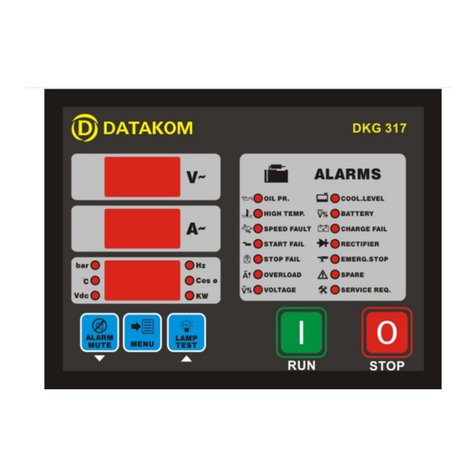
Datakom DKG-705 User manual

Tel: +90-216 466 84 60
Fax: +90-216 364 65 65
DKG-705 AUTOMATIC MAINS FAILURE AND
REMOTE START UNIT
WITH PARALLEL TO MAINS
AND DUAL GENSET PARALLEL FEATURES
FEATURES
Automatic mains failure,
Remote start operation,
Engine control,
Generator protection,
Built in alarms and warnings,
Programmable analogue inputs: 4
Programmable digital inputs: 8
Programmable relay outputs: 7
I/O expansion capability,
LCD display 4 lines by 20 characters,
Periodic maintenance request indicator,
True RMS AC measurements,
Built-in exerciser,
Remote Start capability,
Statistical counters,
Event logging,
Field adjustable parameters,
Governor and AVR control outputs,
No break transfer,
Soft transfer,
Paralleling with the mains,
Peak lopping (peak shaving),
Load shedding,
Dual genset parallel with load sharing,
G-59 protections,
Remote monitoring (MS-Windows based),
RS-232 serial port,
Software downloadable from serial port,
Survives cranking dropouts,
Sealed front panel.
VERSION: 01.16 DATE: 20-02-2006

DATAKOM DKG-705 User’s Manual
705_USER.doc - 2 -
TABLE OF CONTENTS
Section
1. INSTALLATION
1.1. Introduction to the Control Panel
1.2. Mounting the Unit
1.3. Wiring the Unit
2. INPUTS AND OUTPUTS
3. DISPLAYS
3.1. Led Displays
3.2. Digital Display
3.3. Service Request Display
4. ALARMS
4.1. Shutdown Alarms
4.2. Load Dump Alarms
4.3. Warnings
5. MODES OF OPERATION
5.1. External switching of the operation mode
5.2. Remote start operation
6. SYNCHRONIZING WITH MAINS
6.1 Governor Control
6.2. AVR Control
7. LOAD TRANSFER MODES
7.1 Transfer with Interruption
7.2 No Break Transfer
7.3 Soft Transfer
8. PARALLELING WITH MAINS: PEAK LOPPING
9. DUAL GENSET PARALLEL OPERATION
10. PROTECTION FUNCTIONS FOR PARALLEL WITH MAINS
11. LOAD SHEDDING / DUMMY LOAD
12. WEEKLY OPERATION SCHEDULE
13. BUILT-IN EXERCISER
14. EVENT LOGGING
15. STATISTICAL COUNTERS
16. MAINTENANCE
17. SOFTWARE DOWNLOAD
18. PROGRAMMING
19. TROUBLESHOOTING
20. DECLARATION OF CONFORMITY
21. TECHNICAL SPECIFICATIONS
22. CONNECTION DIAGRAM

DATAKOM DKG-705 User’s Manual
705_USER.doc - 3 -
1. INSTALLATION
1.1 Introduction to the Control Panel
The DKG-705 is a control and protection unit used in gensets. The 4 lines by 20 characters LCD
display allows the visualization of many measured parameters. The unit is designed to provide user
friendliness for both the installer and the user. Programming is usually unnecessary, as the factory settings
have been carefully selected to fit most applications. However programmable parameters allow the
complete control over the generating set. Programmed parameters are stored in a Non Volatile Memory
and thus all information is retained even in the event of complete loss of power.
The measurable parameters are:
Mains voltage phase R to neutral
Mains voltage phase S to neutral
Mains voltage phase T to neutral
Mains voltage phase R-S
Mains voltage phase S-T
Mains voltage phase T-R
Mains current phase R (optional)
Mains current phase S (optional)
Mains current phase T (optional)
Mains frequency
Mains KW phase R (optional)
Mains KW phase S (optional)
Mains KW phase T (optional)
Mains KVA phase R (optional)
Mains KVA phase S (optional)
Mains KVA phase T (optional)
Mains KVAr phase R (optional)
Mains KVAr phase S (optional)
Mains KVAr phase T (optional)
Mains cosΦphase R (optional)
Mains cosΦphase S (optional)
Mains cosΦphase T (optional)
Mains total KW (optional)
Mains total KVA (optional)
Mains total KVAr (optional)
Mains total cosΦ(optional)
Gen voltage phase U to neutral
Gen voltage phase V to neutral
Gen voltage phase W to neutral
Gen voltage phase U-V
Gen voltage phase V-W
Gen voltage phase W-U
Gen current phase U
Gen current phase V
Gen current phase W
Gen frequency
Gen KW phase U
Gen KW phase V
Gen KW phase W
Gen KVA phase U
Gen KVA phase V
Gen KVA phase W
Gen KVAr phase U
Gen KVAr phase V
Gen KVAr phase W
Gen cosΦphase U
Gen cosΦphase V
Gen cosΦphase W
Gen total KW
Gen total KVA
Gen total KVAr
Gen total cosΦ
Synchronoscope phase angle
Voltage match U-R
Battery voltage,
Engine RPM
Coolant temperature
Oil pressure
Oil temperature
Fuel level

DATAKOM DKG-705 User’s Manual
705_USER.doc - 4 -
1.2 Mounting the Unit
The unit is designed for panel mounting. The user should not be able to access parts of the unit
other than the front panel.
Mount the unit on a flat, vertical surface. The unit fits into a standard panel meter opening of 188x140
millimeters. Before mounting, remove retaining steel springs from the unit, then pass the unit through the
mounting opening. The unit will be maintained in its position by the steel springs.
The DKG-705 is factory set for 24V-DC operation. If the unit is used in a 12V-DC system, the 12V
jumper terminals must be short-circuited.
Do not operate a 12V-DC unit with a 24V-DC system. This
may cause the destruction of the unit. Always disconnect
the voltage selector jumper of a stocked unit.
The engine body must be grounded for correct operation of the unit. Otherwise incorrect voltage and
frequency measurements may occur, resulting in faulty operation of the genset.
The output of the current transformers shall be 5 Amperes. The input current rating of the current
transformers may be selected as needed (between 50/5 and 5000/5 amps). Current transformer outputs shall
be connected by separate cable pairs from each transformer, to related DKG-705 inputs. Never use common
terminals or grounding. The power rating of the transformer should be at least 5 Watts. It is recommended to
use 1% precision transformers.
If analogue sensors (e.g. temperature, oil pressure, oil temperature or fuel level) are connected to
DKG-705, it is not possible to use auxiliary displays. If temperature or oil pressure displays are already present
on the generator control panel, do not connect the sensors to the DKG-705. The unit is factory programmed
for VDO type sensors. However if a different type of sensor is to be used, it is possible to recalibrate the unit.
The calibration process will be explained later in this document.
The programmable digital inputs are compatible with both ‘normally open’ and ‘normally closed’
contacts, switching either to BAT- or BAT+.
The charge alternator connection terminal provides also the excitation current, thus it is not necessary
to use an external charge lamp.

DATAKOM DKG-705 User’s Manual
705_USER.doc - 5 -
1.3 Wiring the Unit
WARNING: THE UNIT IS NOT FUSED.
Use external fuses for
Mains phases: R-S-T
Generator phase: U-V-W
Battery positive: BAT(+).
Install the fuses as nea
rly as possible to
the unit in a place easily accessible for the user.
The fuse rating should be 6 Amps.
WARNING: ELECTRICITY CAN KILL
ALWAYS disconnect the power BEFORE connecting the unit.
1) ALWAYS remove the plug connectors when inserting wires with a screwdriver.
2) ALWAYS refer to the National Wiring Regulations when conducting installation.
3) An appropriate and readily accessible set of disconnection devices (e.g.
automatic fuses) MUST be provided as part of the installation.
4) The disconnection device must NOT be fitted in a flexible cord.
5) The building mains supply MUST incorporate appropriate short-circuit backup
protection (e.g. a fuse or circuit breaker) of High Breaking Capacity (HBC, at
least 1500A).
6) Use cables of adequate current carrying capacity (at least 0.75mm
2
) and
temperature range.

DATAKOM DKG-705 User’s Manual
705_USER.doc - 6 -
2. INPUTS AND OUTPUTS
12V JUMPER: When this jumper is placed, 12V-DC operation is selected. Do not operate a 12V-DC unit with
a 24V-DC system. This may cause the destruction of the unit. Always disconnect the voltage selector jumper
of a stocked unit.
RS-232 SERIAL PORT: This connector provides serial data input and output for various purposes like
software update, remote monitoring, remote control, remote programming, etc.
EXTENSION CONNECTOR (OPTIONAL): This connector is intended for the connection of input and output
extension modules. The optional relay extension module provides 8 programmable 16A relay outputs. The
DKG-705 allows the use of up to 2 I/O extension modules.
Term Function Technical data Description
1 GENERATOR CONTACTOR Relay output, 10A-AC
This output provides energy to the generator
contactor. If the generator phases do not have
acceptable voltage or frequency values, the
generator contactor will be de-energized. In
standard genset applications, in order to
provide extra security, the normally closed
contact of the mains contactor should be
serially connected to this output. In ‘no break
transfer’ or ‘parallel with mains’
applications, this output will drive directly the
generator contactor.
2 U
3 V
4 W
Generator phase
inputs, 0-300V-AC
Connect the generator phases to these inputs.
The generator phase voltages upper and
lower limits are programmable.
5 GENERATOR NEUTRAL Input, 0-300V-AC Neutral terminal for the generator phases.
6 MAINS NEUTRAL Input, 0-300V-AC Neutral terminal for the mains phases.
7 T
8 S
9 R
Mains phase inputs,
0-300V-AC
Connect the mains phases to these inputs.
The mains voltages upper and lower limits are
programmable.
10 MAINS CONTACTOR Relay output, 10A-AC
This output provides energy to the mains
contactor. If the mains phases do not have
acceptable voltage or frequency values, the
mains contactor will be de-energized. In
standard genset applications, in order to
provide extra security, the normally closed
contact of the generator contactor should be
serially connected to this output. In ‘no break
transfer’ or ‘parallel with mains’
applications, this output will drive directly the
mains contactor.

DATAKOM DKG-705 User’s Manual
705_USER.doc - 7 -
Term Function Technical data Description
11 CURR_W+
12 CURR_W-
13 CURR_V+
14 CURR_V-
15 CURR_U+
16 CURR_U-
Current transformer
inputs, 5A-AC
Connect the generator current transformer
terminals to these inputs. Do not connect the
same current transformer to other units than
DKG-705 otherwise a unit fault will occur.
Connect each terminal of the transformer to
the unit’s related terminal. Do not use
common terminals. Do not use grounding.
Correct polarity of connection is vital. If the
measured power is negative, then change the
polarity of each 3 current transformers. The
rating of the transformers should be the same
for each of the 3 phases. The secondary
winding rating shall be 5 Amperes. (For ex.
200/5 Amps).
17 COOLANT TEMP. SENSOR Input, 0-5000 ohms Analogue temperature sensor connection. Do
not connect the sensor to other devices.
18 OIL PRESSURE SENSOR Input, 0-5000 ohms Analogue oil pressure sensor connection. Do
not connect the sensor to other devices.
19 FUEL LEVEL SENSOR Input, 0-5000 ohms Analogue fuel level sensor connection. Do not
connect the sensor to other devices.
20 OIL TEMP. SENSOR Input, 0-5000 ohms Analogue oil temperature sensor connection.
Do not connect the sensor to other devices.
Term Function Technical data Description
21 PROGRAM LOCK Digital input This input is used to prevent unwanted
modification to programmed values. If this
input is left open, program values can be
modified via the front panel buttons, but if this
input is connected to battery- it will not be
possible to change the program values.
22 DIGITAL INPUT-7
23 DIGITAL INPUT-6
24 DIGITAL INPUT-5
25 DIGITAL INPUT-4
26 DIGITAL INPUT-3
27 DIGITAL INPUT-2
28 DIGITAL INPUT-1
29 DIGITAL INPUT-0
Digital inputs These inputs have programmable functions,
selectable from a list via the program menu.
Each input may be driven by a ‘normally
closed’ or ‘normally open’ contact, switching
either battery+ or battery-. The effect of the
switch is also selectable from a list. See
PROGRAMMING section for more details.

DATAKOM DKG-705 User’s Manual
705_USER.doc - 8 -
Term Function Technical data Description
30 GROUND O VDC Power supply negative connection.
31 CHARGE Input and output Connect the charge alternator’s D+ terminal
to this terminal. This terminal will supply the
excitation current and measure the voltage of
the charge alternator.
32 RELAY-6 (FUEL RELAY) Output 10A/28VDC This relay is normally used for fuel solenoid
control. It is internally connected to terminal 31
for supplying the charge alternator’s excitation
current.
33 RELAY-2 (CRANK RELAY) Output 10A/28VDC This relay has programmable function,
selectable from a list. However it is generally
used as engine crank output.
34 BATTERY POSITIVE +12 or 24VDC The positive terminal of the DC Supply shall
be connected to this terminal. The unit
operates on both 12V and 24V battery
systems, depending on the voltage selection
jumper. Do not operate a 12V-DC unit with a
24V-DC system. This may cause the
destruction of the unit. Always disconnect
the voltage selector jumper of a stocked unit.
35 RELAY-7 (STOP RELAY) Output 10A/28VDC
36 RELAY-1 (PREHEAT) Output 10A/28VDC
37 RELAY-3 (ALARM RELAY) Output 10A/28VDC
These relays have programmable functions,
selectable from a list.
Term Function Technical data Description
38 CURR_R+
39 CURR_R-
40 CURR_S+
41 CURR_S-
42 CURR_T+
43 CURR_T-
Current transformer
inputs, 5A-AC
Connect the mains current transformer
terminals to these inputs. Do not connect the
same current transformer to other units than
DKG-705 otherwise a unit fault will occur.
Connect each terminal of the transformer to
the unit’s related terminal. Do not use
common terminals. Do not use grounding.
Correct polarity of connection is vital. If the
measured power is negative, then change the
polarity of each 3 current transformers. The
rating of the transformers should be the same
for each of the 3 phases. The secondary
winding rating shall be 5 Amperes. (For ex.
200/5 Amps).
Term Function Technical data Description
44 MAGNETIC PICKUP
45 MAGNETIC PICKUP
Inputs, 0.5-70V
0-20KHz
Connect the magnetic pickup signal to these
inputs.
46 AVR CONTROL
47 AVR CONTROL
Output,
isolated resistor,
300-100,000 ohms.
AVR voltage control outputs. Connect to the
external adjust potentiometer terminals of the
AVR. The polarity is not important.
48 GOVERNOR CONTROL Output, 0-10VDC Connect this output to the terminal ‘J’ or ‘EXT’
of the speed governor.

DATAKOM DKG-705 User’s Manual
705_USER.doc - 9 -
3. DISPLAY
3.1 Led Displays
The DKG-705 has 12 leds, divided in 3 groups:
-Group_1: Operating mode: This group indicates the genset function.
-Group_2: Mimic diagram: This group indicates the current status of the mains and
genset
voltages and contactors.
-Group_3: Warnings and alarms: This group indicates the existency of abnormal conditions
encountered during operation.
Function Color Description
MAINS ON Green The LED will turn on when all 3 mains phase voltages
and the mains frequency are within the limits.
MAINS OFF Red The LED will turn on when at least one of the mains
phase voltages or the mains frequency are outside
limits.
GENERATOR Yellow The LED will turn on when all 3 generator phase
voltages are within the programmed limits.
LOAD GENERATOR Yellow It turns on when the generator contactor is activated.
LOAD MAINS Green It turns on when the mains contactor is activated.
LOAD TEST Yellow
TEST Yellow
OFF Green
AUTO Green
It turns on when the related operation mode is
selected. One of these LEDs is always on and
indicates which operation mode is selected.
If the operation of the genset is disabled by the
weekly operation schedule, then the AUTO led will
flash.
ALARM Red It turns on when an engine shutdown or load_dump
condition is occurred.
WARNING Red It turns on when an engine shutdown or load_dump
or warning condition is occurred.
SERVICE REQUEST Red Engine periodic maintenance request indicator. It
turns on when the preset engine hours or time
duration after previous service has elapsed.

DATAKOM DKG-705 User’s Manual
705_USER.doc - 10 -
3.2 Digital Display
The digital display is of LCD type, with 4 lines by 20 characters.
It shows:
-The software version and release date,
-The genset status,
-Measured parameters,
-Alarm information,
-Date and time,
-Service counters,
-Statistical counters,
-Logged events,
-Program parameters.
During power on, the display shows the software version and the release date for 1 seconds.
The display has basically two modes:
-Normal operation,
-Programming mode.
The programming mode will be explained later in this document.
The display is driven by a menu system. The display has many different screens, divided into 3
main groups.
The navigation between different screens in a group is made with the MENU button. Holding the
MENU button pressed for 1 second makes the display to switch to the next group.
During operation, the DKG-705 will switch automatically between different screens, displaying
each time the most important screen for the given situation.
If an alarm or warning occurs during operation other then programming mode, the display will
automatically switch to ALARM LIST position. The MENU button will not allow to switch to other modes.
To enable display navigation, press ALARM MUTE button.
The display has a backlight illumination feature. The backlight turns on with the depression of
any button. It turns off after 1 minute to allow power economy. Also note that the backlight will turn off
during engine cranking.
Group
Screen
Description Contents
1 1 Mains parameters Genset status
Voltage R (or RS), current R, Mains Frequency
Voltage S (or ST), current S
Voltage T (or TR), current T
1 2 Mains parameters Genset status
Voltage RS (or R), current R, Mains Frequency
Voltage ST (or S), current S
Voltage TR (or T), current T
1 3 Basic genset parameters
Genset status
Voltage U (or UV), current U, Genset Frequency
Voltage V (or VW), current V, Genset Active Power (KW)
Voltage W (or WU), current W, Genset Power Factor (cosΦ)
1 4 Basic genset parameters
Genset status
Voltage UV (or U), current U, Genset Frequency
Voltage VW (or V), current V, Genset Active Power (KW)
Voltage WU (or W), current W, Genset Power Factor (cosΦ)

DATAKOM DKG-705 User’s Manual
705_USER.doc - 11 -
Group
Screen
Description Contents
1 5 Engine parameters Engine rpm, Battery Voltage
Coolant Temperature, Fuel Level
Oil Temperature, Oil Pressure
1 6 Genset power Genset Active Power (KW) , Genset Frequency
Genset Apparent Power (KVA), Genset Power Factor
(cosΦ
ΦΦ
Φ)
Genset Reactive Power (KWr)
1 6 Alarm list If no alarm exists this screen will display ‘END OF ALARM
LIST’. Existing alarms, load_dumps and warnings will be
displayed as one screen for each entry. Switching to the
next entry will be made with the MENU button.
Group
Screen
Description Contents
2 1 Genset phase U parameters Phase to Neutral Voltage, Phase Active Power (KW)
Phase Current , Phase Apparent Power (KVA)
Phase Power Factor, Phase Reactive Power (KWr)
2 2 Genset phase V parameters Phase to Neutral Voltage, Phase Active Power (KW)
Phase Current , Phase Apparent Power (KVA)
Phase Power Factor, Phase Reactive Power (KWr)
2 3 Genset phase W parameters Phase to Neutral Voltage, Phase Active Power (KW)
Phase Current , Phase Apparent Power (KVA)
Phase Power Factor, Phase Reactive Power (KWr)
2 4 Synchronoscope Governor Output (%)I AVR Output(%)
Voltage RU, Phase Angle (degrees)
Phase U Voltage, Genset Frequency
Phase R Voltage, Mains Frequency
2 5 Soft transfer parameters Remaining Duration
Governor Output (%), AVR Output(%)
Genset Active Power (KW), Gen. Reactive Power (KWr)
Target Active Power (KW), Target React. Power (KWr)
2 6 Date, time, engine hours Date, Time
Engine Hours Run
2 7 Service display Time to Service
Engine Hours to Service
2 8 Total power counters Total Genset Active Power (KW-h)
Total Genset Apparent Power (KVA-h)
Total Genset Reactive Power (KWr-h)
2 9 Statistical counters Total Engine Cranks
Total Genset Runs
Total Genset on Load
2 10 Mains phase R parameters Phase to Neutral Voltage, Phase Active Power (KW)
Phase Current , Phase Apparent Power (KVA)
Phase Power Factor, Phase Reactive Power (KWr)
2 11 Mains phase S parameters Phase to Neutral Voltage, Phase Active Power (KW)
Phase Current , Phase Apparent Power (KVA)
Phase Power Factor, Phase Reactive Power (KWr)
2 12 Mains phase T parameters Phase to Neutral Voltage, Phase Active Power (KW)
Phase Current , Phase Apparent Power (KVA)
Phase Power Factor, Phase Reactive Power (KWr)
Group Screen
Description Contents
3 1…32 Event logging This group comprises 32 screens, each screen
displaying one recorded event, starting from the most
recent one.

DATAKOM DKG-705 User’s Manual
705_USER.doc - 12 -
3.3 Service Request Display
This led is designed to help the periodic maintenance of the genset to be made consistently.
The periodic maintenance is basically carried out after a given engine hours (for example 200 hours),
but even if this amount of engine hours is not fulfilled, it is performed after a given time limit (for example 365
days).
The SERVICE REQUEST led has no effect on the genset
operation.
The DKG-705 has both programmable engine hours and maintenance time limit. The engine hours is
programmable between 0 and 2500 hours with 10-hour steps (P_624), the time limit is programmable between
0 and 2500 days with 10 day steps (P_625). If any of the programmed values is zero, this means that the
parameter will not be used. For example a maintenance period of 0 days indicates that the DKG-705 will
request maintenance only based on engine hours. There will be no time limit. If the engine hours is also
selected as 0 hours this will mean that the SERVICE REQUEST display will be inoperative.
The remaining engine hours and the remaining time limit are kept stored in a non-volatile memory and
are not modified by power supply failures. The remaining engine hours and time to service may be checked on
the LCD display. (group_2, screen_7)
When the engine hours OR the time limit is over, the SERVICE REQUEST led (red) will start to flash.
To turn off the led, select programming mode, enter factory password and set the parameter_600 to 1, then
check the remaining time and engine hours to service using group_2, screen_7.

DATAKOM DKG-705 User’s Manual
705_USER.doc - 13 -
4. ALARMS
Alarms indicate an abnormal situation in the generating set.
The alarms are divided into 3 priority level:
1- SHUTDOWN ALARMS: These are the most important alarm conditions and cause:
-The genset contactor to be released immediately,
-The engine to be stopped immediately,
-The alarm relay output to operate,
-The ALARM led to turn on,
-The LCD display to switch to alarm display mode (except when programming).
2- LOAD DUMP ALARMS: These conditions cause:
-The genset contactor to be released immediately,
-The engine to be stopped after the cooldown cycle,
-The alarm relay output to operate,
-The ALARM led to turn on,
-The LCD display to switch to alarm display mode (except when programming)
3- WARNINGS: These conditions cause:
-The alarm relay output to operate,
-The WARNING led to turn on.
Most of the alarms are of LATCHING type. Even if the alarm condition is removed, the alarms will stay
on and disable the operation of the genset.
The existing alarms may be canceled by pressing one of the operating mode buttons (LOAD TEST /
TEST / OFF / AUTO) or by pressing the ALARM MUTE button twice.
If the ALARM MUTE button is pressed, the alarm relay output will be deactivated; however the
existing alarms will persist and disable the operation of the genset.
Most of the alarms have programmable trip levels. See the programming chapter for settable alarm
limits.
The digital inputs are programmable and may be set to provide a large variety of alarms and warnings.
See the programming chapter for digital input programming.
The alarms may be cancelled either by pressing any of the front panel mode selection buttons or by a
change in external mode force inputs.

DATAKOM DKG-705 User’s Manual
705_USER.doc - 14 -
4.1 Shutdown Alarms
Definition Source Description
Low Oil Pressure Switch Digital Input
High Eng.Temp.Switch Digital Input
Emergency Stop Digital Input
Low Coolant Level Digital Input
Alternator High Temp. Digital Input
High Oil Temp. Digital Input
Overload Digital Input
Low Fuel Level Digital Input
Battery Charger Fail Digital Input
Spare Alarm 7 Digital Input
Spare Alarm 6 Digital Input
Spare Alarm 5 Digital Input
Spare Alarm 4 Digital Input
Spare Alarm 3 Digital Input
Spare Alarm 2 Digital Input
Spare Alarm 1 Digital Input
These shutdown alarms are set depending on the digital input
settings. The related program parameters are P_700 to P_776.
Gen Under-Frequency Phase U Set if the genset frequency goes under the Low Frequency
Shutdown (P_516) limit for Frequency Timer (P_520) period.
Gen Over Frequency Phase U Set if the genset frequency goes over the High Frequency
Shutdown (P_518) limit for Frequency Timer (P_520) period.
High Battery Voltage Battery Set if the battery voltage goes over the High Battery Voltage
Shutdown (P_610) limit.
Low Fuel Level Analog In. Set if the fuel level measured from analog input goes under the Low
Fuel Level Shutdown (P_608) limit.
High Oil Temperature Analog In. Set if the oil temperature measured from analog input goes over the
High Oil Temperature Shutdown (P_606) limit.
High Coolant
Temperature
Analog In. Set if the coolant temperature measured from analog input goes
over the High Coolant Temperature Shutdown (P_604) limit.
Low Oil Pressure
Measured
Analog In. Set if the oil pressure measured from analog input goes under the
Low Oil Pressure Shutdown (P_602) limit.
Fail To Stop Internal Set if the engine is not stopped before the expiration of the Stop
Timer (P_505).
Fail To Start Internal Set if the engine has not started after Start Attempts (P_504)
number of attempts.
Genset Low Voltage U-V-W Set if any of the genset phase voltages goes under the Generator
Low Limit (P_514) voltage.
Genset High Voltage U-V-W Set if any of the genset phase voltages goes over the Generator
High Limit (P_515) voltage.
Slave Unavailable (dual
genset mode)
Serial
Comm.
Set if a shutdown or load dump alarm has occurred in the slave
genset and Single Genset Load Enable parameter (P_A32) is set
to 0.
Gen Phase Sequence
Fail
U-V-W Set if the generator phase sequence is not correct. This alarm may
be cancelled also by programming the Ignore Phase Order
parameter (P_A06) to 1.
Low Engine Speed Magnetic
Pickup
Set if the engine rpm goes under the Low rpm Shutdown (P_613)
limit. If the Crank Teeth Count (P_619) is set to ‘0’, this alarm will
be disabled.
High Engine Speed Magnetic
Pickup
Set if the engine rpm goes over the High rpm Shutdown (P_615)
limit. If the Crank Teeth Count (P_619) is set to ‘0’, this alarm will
be disabled.
Communication Lost
(dual genset mode)
Serial
Comm.
Set if the serial communication between Master and Slave gensets
is interrupted and Single Genset Load Enable parameter (P_A32)
is set to 0.

DATAKOM DKG-705 User’s Manual
705_USER.doc - 15 -
4.2 Load Dump Alarms
Definition Source Description
Low Oil Press.Switch Digital Input
High Eng.Temp.Switch Digital Input
Emergency Stop Digital Input
Low Coolant Level Digital Input
Alternator High Temp. Digital Input
High Oil Temp. Digital Input
Overload Digital Input
Low Fuel Level Digital Input
Battery Charger Fail Digital Input
Spare Alarm 7 Digital Input
Spare Alarm 6 Digital Input
Spare Alarm 5 Digital Input
Spare Alarm 4 Digital Input
Spare Alarm 3 Digital Input
Spare Alarm 2 Digital Input
Spare Alarm 1 Digital Input
These load dump alarms are set depending on the digital input
settings. The related program parameters are P_700 to P_776.
Gen Reverse Power Internal Set if the genset consumes active power (KW) from the mains and
this power goes over the Reverse Power Load Dump (P_618)
limit.
Gen Excess Power Internal Set if the genset power (KW) supplied to the load goes over the
Excess Power Load Dump (P_617) limit for Overcurrent / Excess
Power Timer (P_511).
Alternator Overcurrent Internal Set if at least one of the genset phase currents goes over the
Overcurrent Limit (P_510) for Overcurrent / Excess Power
Timer (P_511).

DATAKOM DKG-705 User’s Manual
705_USER.doc - 16 -
4.3 Warnings
Definition Source Description
Low Oil Press.Switch Digital Input
High Eng.Temp.Switch Digital Input
Emergency Stop Digital Input
Low Coolant Level Digital Input
Alternator High Temp. Digital Input
High Oil Temp. Digital Input
Overload Digital Input
Low Fuel Level Digital Input
Battery Charger Fail Digital Input
Spare Alarm 7 Digital Input
Spare Alarm 6 Digital Input
Spare Alarm 5 Digital Input
Spare Alarm 4 Digital Input
Spare Alarm 3 Digital Input
Spare Alarm 2 Digital Input
Spare Alarm 1 Digital Input
These warnings are set depending on the digital input settings. The
related program parameters are P_700 to P_776.
Synchronization Fail Internal Set if the phase and voltage synchronization is not successful
before the expiration of Synchronization Fail Timeout (P_A07).
Gen Under-Frequency Phase-U Set if the genset frequency goes under the Low Frequency
Warning (P_517) limit for Frequency Timer (P_520) period.
Gen Over-Frequency Phase-U Set if the genset frequency goes over the High Frequency
Warning (P_519) limit for Frequency Timer (P_520) period.
High Battery Voltage Internal Set if the battery voltage goes over the High Battery Voltage
Warning (P_611) limit.
Low Fuel Level Analog
Input
Set if the fuel level measured from analog input goes under the Low
Fuel Level Warning (P_609) limit.
High Oil Temperature Analog
Input
Set if the oil temperature measured from analog input goes over the
High Oil Temperature Warning (P_607) limit.
High Coolant
Temperature
Analog
Input
Set if the coolant temperature measured from analog input goes
over the High Coolant Temperature Warning (P_605) limit.
Low Oil Pressure
Measured
Analog
Input
Set if the oil pressure measured from analog input goes under the
Low Oil Pressure Warning (P_603) limit.
Mains Phase Sequence
Fail
R-S-T Set if the mains phase sequence is not correct and Ignore Phase
Order (P_A06) parameter is ‘0’.
Charge Failure Charge
input
Set if the Charge input (terminal_31) is pulled to battery negative
when the engine is running.
Low Battery Voltage Internal Set if the battery voltage goes under the Low Battery Voltage
Warning (P_612) limit.
AVR Control Fail Internal Set if the AVR control output has gone to the low or high limit
value for 1 second.
GOV Control Fail Internal Set if the GOV control output has gone to the low or high limit
value for 1 second.
Low Engine Speed Magnetic
Pickup
Set if the engine rpm goes under the Low rpm Warning (P_614)
limit. If the Crank Teeth Count (P_619) is set to ‘0’, this warning will
be disabled.
High Engine Speed Magnetic
Pickup
Set if the engine rpm goes over the High rpm Warning (P_616)
limit. If the Crank Teeth Count (P_619) is set to ‘0’, this warning will
be disabled.

DATAKOM DKG-705 User’s Manual
705_USER.doc - 17 -
Definition Source Description
Parallel Mains Fail Internal This general warning is set if any of the protection functions have
detected a mains failure during parallel with mains operation.
Mains Reverse Power Internal In parallel with mains operation and after the parallel check
timeout delay (P_A23) has elapsed, this warning will be set if the
mains power is negative and over the reverse power limit defined in
P_A24.
Mains Frequency Fail R In parallel with mains operation and after the parallel check timeout
delay (P_A23) has elapsed, this warning will be set if the mains
frequency is out of the limits defined in P_522 and P_523 for 4
consecutive cycles.
No Mains Frequency R In parallel with mains operation and after the parallel check timeout
delay (P_A23) has elapsed, this warning will be set if the mains
frequency disappears for more than 2,5 periods.
ROCOF (df/dt) Fail R In parallel with mains operation and after the parallel check timeout
delay (P_A23) has elapsed, this warning will be set if the mains
frequency change exceeds the limit defined in P_A25 for 4
consecutive cycles.
Vector Shift (df/dt) Fail R In parallel with mains operation and after the parallel check timeout
delay (P_A23) has elapsed, this warning will be set if the phase of
the mains measured on last 2 cycles jumps over the limit defined
in P_A26 on the phase measured on last 4
th
and 5
th
period.
Communication Lost
(dual genset mode)
Serial
Comm.
Set if the serial communication between Master and Slave gensets
is interrupted and Single Genset Load Enable parameter (P_A32)
is set to 1.

DATAKOM DKG-705 User’s Manual
705_USER.doc - 18 -
5. MODES OF OPERATION
The modes of operation are selected either by pushing the front panel keys or using the external mode
select inputs. External inputs override the front panel selection. If none of the external inputs is active, the unit
resumes to the mode selected by the front panel. Following selected mode, the DKG-705 will have different
behavior.
OFF: In this mode, the mains contactor will be energized if mains phase voltages and frequency are within the
programmed limits. The engine will be stopped.
AUTO: It is used for genset and mains automatic transfer. If at least one of the mains phase voltages or the
mains frequency is outside limits, the mains contactor will be deactivated.
The diesel will be started for programmed times after the wait period. When the engine runs, the crank relay
will be immediately deactivated. The engine will run without load during engine heating period. After this, if
alternator phase voltages and frequency are within limits, the unit will wait for the generator contactor period
and the generator contactor will be energized.
When all the mains phase voltages and the mains frequency are within the limits, the engine will continue to
run for the mains waiting period. At the end of this period the generator contactor is deactivated and the mains
contactor will be energized. If a cooling period is given, the generator will continue to run during cooling period.
At the end of the period, the fuel solenoid will be de-energized and the diesel will stop. The unit will be ready
for the next mains failure.
If the operation of the genset is disabled by the weekly schedule, then the AUTO led will flash, and the
operation of the genset will be as in the OFF mode.
LOAD TEST: It is used to test the genset under load. Once this mode is selected, the engine will run and the
load will be transferred to the genset. The genset will feed the load indefinitely unless another mode is
selected.
TEST: It is used to test the generator when the mains are on, or keep the generator waiting in the emergency
backup mode. The operation of the generator is similar to the AUTO mode, but the mains contactor will not be
deactivated if the mains are not off. If the mains are off, mains contactor will be deactivated and the generator
contactor will be activated. When the mains are on again, a changeover to the mains will be made, but the
engine will be kept running unless another mode is selected. The emergency backup operation may be
prohibited using the program parameter P_629.
5.1 External Switching of the Operation Mode
The Mode of operation of the unit may also be selected by external inputs instead of front panel keys.
For this, at least one of the digital inputs should be programmed as an input to force one of the 4 operating
modes. The corresponding input’s P_7x0 parameter should be set to 18, 19, 20 or 21. The mode selection
signal may be a NO or NC contact, switching to either battery positive or battery negative. These selections
are made using parameters P_7x5 and P_7x6.
The external selection input has a higher level of priority than the front panel keys. Thus if the
operating mode is forced by the external input, this will override the selection made by the front panel keys.
However, when the external selection signal goes off, the unit will resume to the mode selected by the front
panel keys.
If a front panel mode selection key is pressed while the external mode select input is active, then the
key selection will be stored and when the external selection signal goes off, the unit will resume to this mode.

DATAKOM DKG-705 User’s Manual
705_USER.doc - 19 -
5.2. Remote Start Operation
The unit offers the possibility of REMOTE START mode of operation. In this mode the mains
phases are not monitored. If the REMOTE START signal is present then the mains will be supposed to fail,
inversely if the REMOTE START signal is absent, then mains voltages will be supposed to be present. The
front panel mimic diagram’s mains LEDs will reflect the status of the REMOTE START input.
Any of the digital inputs may be programmed as a REMOTE START input. For this the
corresponding input’s P_7x0 parameter should be set to 23. The REMOTE START signal may be a NO or NC
contact, switching to either battery positive or battery negative. These selections are made using parameters
P_7x5 and P_7x6.

DATAKOM DKG-705 User’s Manual
705_USER.doc - 20 -
6. SYNCHRONIZING WITH MAINS
The DKG-705 offers the possibility of synchronizing the genset with the mains.
The synchronization comprises frequency, phase and voltage matching features.
The synchronization properties of the unit are adjusted with program parameters.
These parameters are reserved for factory and qualified installation
personal use and must not be modified by end users or non-qualified
service personal. Otherwise severe damage may occur!
6.1 Governor Control
The frequency and phase matching is made by controlling the engine’s governor module. The
DKG-705 compares the mains phase R with the genset phase U. If the engine does not have a speed
governor it is not possible to make frequency or phase control.
The GOV output (terminal 45) is an analog voltage output of 0-10 VDC. The output impedance is
180 ohms.
The functions of the GOV output are controlled by programmed parameters:
P_A02 GOV Control Enable: This parameter enables/disables the activation of the governor control
output. If governor control is disabled, the output will always stay at the rest level defined by P_A13.
P_A03 GOV Reverse Polarity: In normal polarity, the governor control voltage increases in order to
increase the engine speed. If reverse polarity is selected the governor control voltage decreases in order to
increase the engine speed.
P_A13 Governor Start: This is the rest value of the governor control output. Always set this value to 128,
which is the mid-course, and then adjust the engine speed from the speed governor. However, if needed,
engine speed adjustment may be made through this parameter. Do not forget that, if this parameter is
modified, the adjustment range will be reduced.
P_A15 Frequency Lock Gain: This parameter defines the reaction speed of the governor output to phase
differences between genset and mains phases during synchronization. The standard value for this
parameter is 32. But it must be readjusted for the engine during manufacturing. If this parameter is too
high, a phase oscillation may occur. If it is too low, the phase locking will have a lazy behavior.
Table of contents
Other Datakom Remote Starter manuals
Popular Remote Starter manuals by other brands

ATD Tools
ATD Tools 5928 owner's manual

Firstech
Firstech CM6200 installation manual

RED FUEL
RED FUEL SL161 owner's manual

Directed Electronics
Directed Electronics SmartStart 5000-series owner's guide

Audiovox
Audiovox Prestige 128-7852A owner's manual
Tactical technologies
Tactical technologies TX-500 operating instructions
