manuals.online logo
Brands
  1. Home
  2. •
  3. Brands
  4. •
  5. Datakom
  6. •
  7. Remote Starter
  8. •
  9. Datakom DKG-154 User manual

Datakom DKG-154 User manual

DKG-154
REMOTE START UNIT
INSTALLATION AND OPERATING INSTRUCTIONS
The DATAKOM model DKG-154 is a low cost,
microprocessor controlled unit designed to start
and stop the genset automatically on request of an
external Remote Start signal.
When the engine is running, the unit monitors fault
conditions and shuts-down the engine automatically
in the occurrence of an alarm. The alarms are
identified by a group of LEDs displaying only the
first occurring one.
The unit has jumper selectable options for the
auxiliary relay output function. The selection is
made by the position of a single jumper situated at
the left side panel of the unit.
If the jumper is placed between:
A & B : 50 Hz nominal, AUX is Preheat output
B & C : 60 Hz nominal, AUX is Preheat output
C & D : 60 Hz nominal, AUX is Stop output
D & A : 50 Hz nominal, AUX is Stop output
In the OFF position, the DC supply is removed from
the module, thus remote start operation is disabled
and zero power consumption is achieved.
The unit powers up when the AUTO position on the
front panel is selected. It will start the engine when
its Remote Start input is pulled to battery negative
and will act like below:
If ‘Preheat’ option is selected, it energizes the
AUXILIARY output for Preheat Delay, then
releases it.
Then it energizes the FUEL output for Wait Before
Start delay, then energizes the START output for
Start Duration. If the engine fires, the start output
is immediately released. The protections will be
enabled only after the Protection Hold-off Timer
has expired.
If the engine does not fire, start and fuel outputs are
deenergized, if ‘Preheat’ option is selected, the
AUXILIARY output will be energized and the unit
will wait for Wait Between Starts period before a
new crank cycle is initiated. The engine is cranked
up to 3 times.
If the Remote Start signal disappears while the
engine is running, the engine will continue to run for
Cooldown Duration. Then the fuel output is
deenergized, if the ‘Activate to Stop’ option is
selected, the AUXILIARY output will be energized
for Stop Timer, and the unit will be ready for a new
Remote Start.
The PREHEAT/STOP ( ) led will continuously
indicate the AUXILIARY output status.
The occurrence of below fault conditions will cause
the engine to be stopped immediately:
-Overspeed,
-Underspeed,
-High engine temperature,
-Low oil pressure,
If a fault condition occurs, the FUEL solenoid will
be deenergized. If the ‘Energize to Stop’ option is
selected, the AUXILIARY output will be energized
during Stop Timer and the led associated with this
fault condition will turn on.
Only the first occurring fault will be indicated. To
reset the fault condition, turn the switch to the OFF
position for a few seconds.
The Charge Fail condition is treated as a warning
only and do not cause the engine to stop. The input
monitors the D+ terminal of the charge alternator.
OPERATION
DESCRIPTION
DC SUPPLY: 12 or 24 volts DC, (+) and (-) terminals.
L1:Generator phase voltage.
NEUTRAL: Generator neutral terminal.
HIGH TEMP SWITCH: Negative closing switch input.
LOW OIL PRESSURE: Negative closing switch input.
REMOTE START: A negative supply connection to this
input will cause the engine to run.
CHARGE: Connect the charge alternator’s D+ end to
this terminal. This terminal will supply the excitation
current and measure the voltage of the charge
alternator.
FUEL SOLENOID, START, AUXILIARY: These are
fully protected, negative pulling solid state outputs.
Each output is rated 1.2amps@28V-DC.
JUMPER SELECTABLE STANDARD
FEATURES:
Preheat with Activate to Start,
Energize to Stop without preheat,
50Hz nominal,
60Hz nominal.
OPTIONAL FEATURES:
(SUBJECT TO SPECIAL ORDER)
Engine control (without alternator),
Manual Start version (DKG-151)
Negative pulling semiconductor outputs (DKG-154).
Customized timer values.
Alternator Voltage: 15 to 300 V-AC
Alternator Frequency: 50 or 60 Hz nominal.
Overspeed: nominal frequency + 14%
(+24% overshoot)
Underspeed: 25Hz
DC Supply Range: 8 to 33 V-DC.
Current consumption: 80mA max. (Outputs open).
Charge fail threshold: 6 V-DC.
Charge excitation current: via 82 ohms resistor
connected to the FUEL output.
Preheat Delay: 10 sec.
Wait Before Start: 0.75 sec.
Start Duration: 6 sec.
Wait Between Starts: 10 sec.
Number of Start Cycles: 3
Protection Hold-off Timer: 12 sec.
Cooldown Duration: 2 minutes.
Stop Timer: 30 sec.
Operating temp.: -20C (-4F) to 70 C (158F).
Storage temp.: -30C (-22F) to 80 C (176F).
Maximum humidity: 95% non-condensing.
Dimensions: 72x72x38mm (WxHxD)
Panel cutout dimensions: 68x68 mm
Weight: 100g (approx.)
Installation: Front panel mounted. Retaining steel
spring provided.
DATAKOM Electronics Ltd.
Tel: +90-216-466 84 60 Fax: +90-216-364 65 65 e-mail: datako[email protected].tr http: www.datakom.com.tr
TECHNICAL SPECIFICATIONS
OPTIONS
OUTPUTS
INPUTS
TYPICAL CONNECTION DIAGRAM

Other Datakom Remote Starter manuals

Datakom DKG-317 User manual

Datakom

Datakom DKG-317 User manual

Datakom DKG-116 User manual

Datakom

Datakom DKG-116 User manual

Datakom DKG-705 User manual

Datakom

Datakom DKG-705 User manual

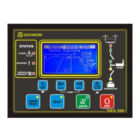
Datakom DKG-309 User manual

Datakom

Datakom DKG-309 User manual

Datakom DKG-119J User manual

Datakom

Datakom DKG-119J User manual

Popular Remote Starter manuals by other brands

Directed Electronics DB3 installation guide

Directed Electronics

Directed Electronics DB3 installation guide

NOCO Genius Boost X GBX75 User guide & warranty

NOCO Genius

NOCO Genius Boost X GBX75 User guide & warranty

wattstunde WS-JS manual

wattstunde

wattstunde WS-JS manual

Voxx Electronics Prestige APS997Z Quick installation guide

Voxx Electronics

Voxx Electronics Prestige APS997Z Quick installation guide

Audiovox PURSUIT PRO9276TW owner's manual

Audiovox

Audiovox PURSUIT PRO9276TW owner's manual

Audiovox AS-9055T owner's manual

Audiovox

Audiovox AS-9055T owner's manual

Mopar 82211019xx Jeep Commander (XK) 2008 installation instructions

Mopar

Mopar 82211019xx Jeep Commander (XK) 2008 installation instructions

New Easy Electronics CPT-JSS00-01 product manual

New Easy Electronics

New Easy Electronics CPT-JSS00-01 product manual

Prestige PE5BZ owner's guide

Prestige

Prestige PE5BZ owner's guide

Directed Xpresskit DBALL2 installation guide

Directed

Directed Xpresskit DBALL2 installation guide

CRX CRX1223 instruction manual

CRX

CRX CRX1223 instruction manual

Fortin EVO-ALL Electrical Wiring Manual

Fortin

Fortin EVO-ALL Electrical Wiring Manual

Firstech FT-MB211-DC installation guide

Firstech

Firstech FT-MB211-DC installation guide

Fortin ORBIT F3400 Quick installation guide

Fortin

Fortin ORBIT F3400 Quick installation guide

DoorKing 1504-096 Installation and owner's manual

DoorKing

DoorKing 1504-096 Installation and owner's manual

KBi KrankingKART Mini HD manual

KBi

KBi KrankingKART Mini HD manual

Stanley FatMax J45TK quick start guide

Stanley FatMax

Stanley FatMax J45TK quick start guide

Pyle PWD303 INSTALLAER’S GUIDE

Pyle

Pyle PWD303 INSTALLAER’S GUIDE

manuals.online logo
manuals.online logoBrands
  • About & Mission
  • Contact us
  • Privacy Policy
  • Terms and Conditions

Copyright 2025 Manuals.Online. All Rights Reserved.