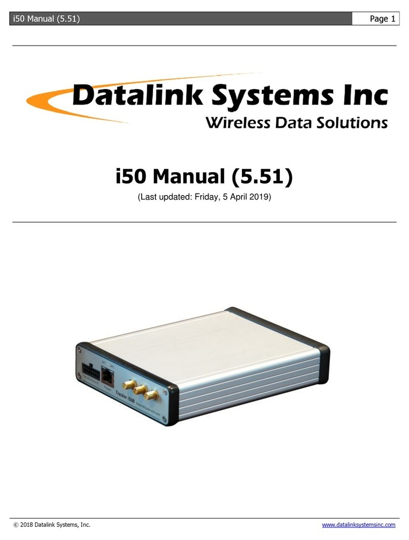
Datalink Systems i50 User manual

i50 Manual (4.33) Page 1
© 2009 Datalink Systems, Inc. .datalinksystemsinc.com
Datalink Systems, Inc.
TECHNICAL DOCUMENTATION
i50 Manual (4.33)
(Last updated: Friday, 27 November 2009)

i50 Manual (4.33) Page 2
© 2009 Datalink Systems, Inc. .datalinksystemsinc.com
Contents
1.0 Safety Precautions..........................................................................................................................4
1.1 RF Exposure ...............................................................................................................................4
1.2 Antenna Gain ..............................................................................................................................4
1.3 GPRS Human Exposure Compliance Statement ........................................................................4
1.4 Iridium Human Exposure Compliance Statement........................................................................4
1.5 Servicing .....................................................................................................................................4
2.0 i50 Overview ...................................................................................................................................5
3.0 Specifications..................................................................................................................................6
4.0 Connections....................................................................................................................................7
4.1 Power and I/O Connector............................................................................................................8
4.2 VOUT Power Source...................................................................................................................8
4.3 Program Connector.....................................................................................................................9
4.4 LED Status Indicators ...............................................................................................................10
4.5 COM Connectors ......................................................................................................................11
4.5.1 COM1 .................................................................................................................................11
4.5.2 COM2/COM3......................................................................................................................11
4.5.3 Using Program connector to access COM1........................................................................12
4.6 Antenna Connectors .................................................................................................................12
5.0 Installation.....................................................................................................................................13
5.1 Power Supply ............................................................................................................................13
5.2 I/O Connections ........................................................................................................................13
5.3 COM Connections.....................................................................................................................13
5.4 Antennas ...................................................................................................................................14
5.5 Initial Set Up..............................................................................................................................14
6.0 Operation......................................................................................................................................15
6.1 LEDs .........................................................................................................................................15
6.2 Power Modes ............................................................................................................................15
6.2.1 Power Up............................................................................................................................15
6.2.2 Entering Sleep Mode ..........................................................................................................15
6.2.3 Returning to Awake Mode ..................................................................................................16
6.2.4 Periodic Wakeup ................................................................................................................16
6.3 Network .....................................................................................................................................16
6.4 Error Handling ...........................................................................................................................16
7.0 Configuration ................................................................................................................................17
7.1 Connecting a PC to the i50 .......................................................................................................17
7.2 Programming.............................................................................................................................18
7.2.1 Programmer Toolbar...........................................................................................................18
7.2.2 Settings...............................................................................................................................19
7.2.3 Waypoints...........................................................................................................................23
7.3 Device Info ................................................................................................................................24
7.3.1 Status .................................................................................................................................24
7.3.2 Inputs..................................................................................................................................24
7.3.3 Other...................................................................................................................................24
7.4 Device Ports Window ................................................................................................................25
7.4.1 Direct Mode ........................................................................................................................26

i50 Manual (4.33) Page 3
© 2009 Datalink Systems, Inc. .datalinksystemsinc.com
7.4.2 Wi-Fi Firmware Update.......................................................................................................26
7.5 Test Window .............................................................................................................................27
8.0 Port Assignment ...........................................................................................................................28
8.1 PDT-100....................................................................................................................................28
8.2 Sentry........................................................................................................................................28
8.3 RF .............................................................................................................................................28
8.4 Palm Pilot ..................................................................................................................................28
8.5 Dial-Up ......................................................................................................................................28
8.6 Transparent...............................................................................................................................29
8.7 Ext. GPS ...................................................................................................................................29
8.8 J1708 ........................................................................................................................................29
8.9 Alarm Interface..........................................................................................................................29
8.10 Grace Pager............................................................................................................................29
8.11 GPRS/CDMA ..........................................................................................................................30
8.12 Globalstar................................................................................................................................30
8.13 Accelerometer .........................................................................................................................30
8.14 Iridium .....................................................................................................................................31
8.15 Wi-Fi........................................................................................................................................31
8.16 Garmin ....................................................................................................................................31
9.0 Dial-Up/Wi-Fi Interface .................................................................................................................32
9.1 Dial-Up Configuration................................................................................................................32
9.1.1 Adding i50 modem to Windows XP ....................................................................................32
9.1.2 Adding a Windows XP dial-up connection ..........................................................................32
9.2 Wi-Fi Configuration ...................................................................................................................33
9.3 Connection Details ....................................................................................................................33
9.3.1 GPS over UDP ...................................................................................................................33
9.3.2 Transparent data over UDP................................................................................................33
10.0 Garmin Interface .........................................................................................................................35
11.0 I/O Configuration.........................................................................................................................36
11.1 Inputs ......................................................................................................................................36
11.2 Outputs....................................................................................................................................36
11.3 Alarm Mode.............................................................................................................................36
11.3.1 Alarm Input .......................................................................................................................36
11.3.2 Alarm Output ....................................................................................................................37
12.0 Firmware Updates ......................................................................................................................38
13.0 Programming Settings from DataGate........................................................................................40
13.1 Integer Values .........................................................................................................................40
13.2 String Values...........................................................................................................................44
14.0 Contact Information ....................................................................................................................45

i50 Manual (4.33) Page 4
© 2009 Datalink Systems, Inc. .datalinksystemsinc.com
1.0 Safety Precautions
This product may contain one or more radio frequency (RF) transmitters. For safety reasons, the
following operating conditions and restrictions must be observed at all times.
1.1 RF Exposure
1.2 Antenna Gain
1.3 GPRS Human Exposure Compliance Statement
Enfora certifies that the Enfora Enabler IIIG 850/900/1800/1900 MHz GSM Radio Module (FCC ID:
MIVGSM0308) used in this product complies with the RF hazard requirements applicable to
broadband PCS equipment operating under the authority of 47 CFR Part 24. Subpart E and Part 24
of the FCC Rules and Regulations. This certification is contingent upon installation, operation and
use of the i50B in accordance with all instructions provided to the end user. When installed and
operated in a manner consistent with the instructions provided, the Enfora Enabler IIIG module meets
the maximum permissible exposure (MPE) limits for general population / uncontrolled exposure as
defined in Section 1.1310 of the FCC Rules and Regulations.
1.4 Iridium Human Exposure Compliance Statement
The Iridium 9601 modem is certified under 47 CFR Part 25 as FCC ID: Q639601. It also complies
with Part 15 of the FCC Regulations. Operation is subject to the condition that this device does not
cause harmful interference. Any changes or modifications, including the use of a non-standard
antenna, not expressly approved by the party responsible for compliance could void the user's
authority to operate the equipment.
1.5 Servicing
The i50B modems must only be serviced by a qualified technician.
The maximum permitted Iridium antenna gain
is limited to 3 dBi
The maximum permitted GPRS antenn
a gain
is limited to 2 dBi
WARNING
A separation distance of 20 cm
(7.9”) or more must be maintained between
any i50B antenna and all persons.

i50 Manual (4.33) Page 5
© 2009 Datalink Systems, Inc. .datalinksystemsinc.com
2.0 i50 Overview
The i50 is Datalink’s intelligent asset tracking unit. It is designed for automatic vehicle location (AVL)
and two-way data transfer over multiple wireless communications networks via the Datalink DataGate
server software. It includes an internal GPS receiver and optional internal modems for a complete
solution in one box. Two main i50 versions are produced: the i50B for general commercial use; and
the i50C, which includes support for AES-256 encryption.
Standard and optional features include:
•50-channel GPS receiver (supports GPS and GALILEO
1
signals)
•Internal satellite and cellular modems with dual operation (optional)
•Internal Wi-Fi modem (optional)
•Three external RS-232 serial ports (only two available when using internal Wi-Fi)
•Sleep mode with adjustable timeout and periodic wakeup timer
•Wide input voltage range with load-dump protection
•Battery voltage monitoring
•Four digital inputs plus Ignition input
•Four digital outputs
•Two analog inputs
•Switched power output for driving external devices
•Internal flash memory for permanent storage of unit settings
•Internal data buffer with backup battery eliminates data loss
•Internal 3D accelerometer to monitor driving style and detect movement while in sleep mode
•External J1708 engine interface (optional)
•Panic alert mode
•SCADA ready
•Remote programmable
•Real-time clock (RTC) timestamps events as they occur
The three external serial ports allow the i50 to interface with external devices, including:
•Cellular modem (GPRS/CDMA)
•Satellite modem (Iridium/Inmarsat D+/Globalstar/MSat)
•Sentry 2-way pager system
•RF modem (point-to-point and trunked)
•Magnetic card reader
•Laptop
•Third-party devices
•J-1708 engine interface
Other devices and networks can be made available with custom development.
1
Available through GPS firmware update when Galileo system becomes operational.

i50 Manual (4.33) Page 6
© 2009 Datalink Systems, Inc. .datalinksystemsinc.com
3.0 Specifications
Size: 168 mm x 128 mm x 39 mm (L x W x H) (excluding connectors)
Supply Voltage: 7 - 28 VDC continuous operation
1
Vehicle load-dump protection (internal resettable fuse)
2
Reverse polarity protection up to 60 VDC
Current (@ 12 V input): Normal operation (no modems or GPS): 45 mA
3
GPS: Add 28 mA (55 mA during acquisition) excluding antenna.
Cellular: Add 25 mA (220 mA during TX)
4
Satellite: Add 34 mA (180 mA during TX)
4
Wi-Fi: Add 130 mA
Sleep mode: 5 mA
3
Internal Battery: CR2032 lithium cell (user replaceable)
3-year shelf life (no external power applied)
10-year life while external power is applied
Temperature Range: -20°C to 50°C (operating)
-30°C to 60°C (storage)
-40°C to 85°C (storage with internal battery removed)
External Serial Ports: RS-232 ESD protected
COM1: full handshaking (port unavailable when using internal Wi-Fi)
COM2: full handshaking
COM3: three-wire (TX/RX/GND)
Switched Power Output: 1.3 A continuous (internal resettable fuse)
Vehicle load-dump protection
2
Short circuit protection (9 A max)
Output voltage equals supply voltage minus one diode drop
Digital Inputs: Maximum voltage range: +/- 200 V
Digital low level: < 1.3 V
Digital high level: > 6.5 V
10 KΩpull-up resistance (excluding IGN input)
Digital Outputs: Low-side switches (no pull-ups)
Load voltage up to 60 V
170 mA continuous per output (internal resettable fuse)
Short circuit protection (9 A max)
Analog Inputs: Maximum voltage range: +/- 200 V
Measurement range: 0 - 36 V (12-bit resolution)
GPS: U-Blox LEA-5H 50-channel receiver
Tracks signals down to –160 dBm
Active antenna connector (3.3 V output. 30 mA max)
Accelerometer: +/- 2 g in X, Y and Z directions
Clock: Built-in real time clock with battery backup
Temperature Sensor: Internal temperature sensor (-40°C to 125°C)
1
7 - 21 VDC on units with serial numbers from 15020000 to 15029999.
2
Internal fuses are slow acting. An over-voltage condition on a current-limited supply could cause permanent damage.
3
Supply current will increase when external I/O, VOUT, or serial lines are connected. Current is also inversely
proportional to input voltage (input power remains constant).
4
Average TX currents shown. Instantaneous peak cellular or satellite modem current can reach 1.5 A at 12 V.

i50 Manual (4.33) Page 7
© 2009 Datalink Systems, Inc. .datalinksystemsinc.com
4.0 Connections
Figure 1 and Figure 2 show the front and back panels of the i50. Each external feature is described
below.
Figure 1 – Front Panel
Figure 2 – Back Panel
Pwr & I/O: Main power and input/output (I/O) connector (see section 4.1)
Program: RJ-45 connector for updating unit firmware (see section 4.2)
NET LED: Network status indicator (see section 4.4 for LED information)
GPS LED: GPS status indicator
Wi-Fi: SMA connector for Wi-Fi antenna (optional)
Iridium: SMA connector for Iridium antenna (optional)
GPRS: SMA connector for GPRS antenna (optional)
COM1: Female RS-232 port (full handshaking)
COM2: Male RS-232 port (full handshaking)
COM3: Male RS-232 port (three-wire)
GPS: SMA connector for GPS antenna. This connector provides a 3.3 VDC
output for an active antenna. The i50 will turn off this voltage if it detects
a shorted antenna cable, and periodically retry applying power until the
fault is corrected.

i50 Manual (4.33) Page 8
© 2009 Datalink Systems, Inc. .datalinksystemsinc.com
4.1 Power and I/O Connector
Table 1 shows the pin assignment of the 14-pin power and input/output connector, shown looking into
the connector on the front panel.
PWR IGN IN1 IN2 IN3 IN4 ADC1
GND VOUT OUT1 OUT2 OUT3 OUT4 ADC2
Table 1 – Power & I/O Connector
PWR: Positive supply. Note: continuous voltage on this pin MUST NOT exceed the
rated maximum.
IGN: Vehicle Ignition (active high)
IN1: Digital Input 1
IN2: Digital Input 2
IN3: Digital Input 3
IN4: Digital Input 4
ADC1: Analog Input 1
GND: Negative supply (ground)
VOUT: Switched power supply output. See section 4.2 for more information.
OUT1: Digital Output 1
OUT2: Digital Output 2
OUT3: Digital Output 3
OUT4: Digital Output 4. This output pin is not currently available for user control. It is hard
coded to an active-low state in firmware versions 4.11 or later.
ADC2: Analog Input 1
See section 3.0 for detailed specifications on these pins.
4.2 VOUT Power Source
The VOUT line provides a switched power output, allowing the i50 to turn an external device on or
off. VOUT is active (power turned on) when the i50 is awake, and disabled during sleep mode. Note:
this output is not activated during a periodic wakeup event, when the unit is only awake for a short
time (see section 6.2.2).
This output is available on the power and Program connectors, as well as COM3 (factory option).
Note: the maximum continuous VOUT current is 1.3 A, which is shared between all VOUT
lines.

i50 Manual (4.33) Page 9
© 2009 Datalink Systems, Inc. .datalinksystemsinc.com
4.3 Program Connector
The i50 Program connector is used to update the unit’s firmware and adjust settings. It may also be
used to access the i50 COM1 port (see section 4.5.3). Firmware can be updated by connecting a PC
to the Program port and running the firmware update utility.
Table 2 shows the pin assignment of the Program connector, including the connections required to
attach a female DB-9 connector. Pin 1 is located on the right side looking into the connector on the
front panel. All pins (except VOUT and GND) use RS-232 voltage levels.
RJ
-
45 Pin
Pin Name
Direction (relativ
e to i50
)
DB
-
9 Pin (female
)
1 VOUT Output -
2 MODE Input 7 (RTS)
3 RX Input 3 (TX)
4 STATUS Output 6 (DSR)
5 TX Output 2 (RX)
6 RESET Input 4 (DTR)
7 Not used - -
8 GND - 5 (GND)
Table 2 – Program Connector
VOUT: Switched power output. See section 4.2 for more information
MODE: Used to enter firmware programming mode
RX: Data input
STATUS: Indicates CPU mode
TX: Data output
RESET: Used to reset CPU
GND: Ground
Note: this pin layout has been chosen so that a Datalink Mobile Data Terminal (MDT) can be plugged
in using a standard RJ-45 to RJ-45 LAN cable. The MDT provides an LCD screen and keypad for
applications where an advanced user interface is required.

i50 Manual (4.33) Page 10
© 2009 Datalink Systems, Inc. .datalinksystemsinc.com
4.4 LED Status Indicators
The i50 has two light-emitting diodes (LEDs) attached to the Program connector on the front panel.
These lights flash to indicate what mode the unit is in. The following states can be shown:
Power Up: NET and GPS LEDs turn green briefly when power is applied
No Settings: NET and GPS LEDs flash red four times per second
Programming: NET and GPS LEDs flash twice per second
Error: NET and GPS LEDs alternate red rapidly (see section 6.4)
Sleeping: NET LED flashes orange (red plus green) every two seconds
GPS LED off
When the unit is in normal operating mode, the LEDs are used to show network and GPS status, as
follows:
NET LED: Red flashes: no network
Green flashes: network OK
One flash per second: no data in buffer
Two flashes per second: data waiting to be sent
Three flashes per second: alarm active (ACK received)
Four flashes per second: alarm active (waiting for ACK)
GPS LED: Red flashes: no GPS signal - check antenna position
Green flashes: GPS signal OK
One flash per second: GPS antenna OK
Four flashes per second: GPS antenna short circuit

i50 Manual (4.33) Page 11
© 2009 Datalink Systems, Inc. .datalinksystemsinc.com
4.5 COM Connectors
The i50 has three external DB-9 serial connections: COM1, COM2 and COM3. These all use RS-232
levels, and automatically enter power savings mode when no input signals are detected.
4.5.1 COM1
COM1 has a female connector, through which the i50 acts as a DCE (data communication
equipment). This is intended for connection to a PC or other terminal, but can be used for any
purpose. See Table 3 for pin descriptions.
DB
-
9 Pin (female)
Pin Name
Direction (relative to i50
)
1 DCD Output
2 RX Output
3 TX Input
4 DTR Input
5 GND -
6 DSR Output (always high)
7 RTS Input
8 CTS Output
9 RI Output
Table 3 – COM1 Connector
Note: the COM1 DSR pin is always set to a high state when COM1 is enabled.
4.5.2 COM2/COM3
COM2 and COM3 use male connectors, through which the i50 acts as a DTE (data terminal
equipment). These are intended to connect to external modems, but may also be used for other
purposes.
COM2 provides full handshaking and control pins, allowing full control of external devices and
hardware flow control to prevent data loss. Table 4 shows the COM2 pin descriptions.
DB
-
9 Pin (male)
Pin Name
Direction (relative
to i50
)
1 DCD Input
2 RX Input
3 TX Output
4 DTR Output
5 GND -
6 DSR Input
7 RTS Output
8 CTS Input
9 RI Input
Table 4 – COM2 Connector

i50 Manual (4.33) Page 12
© 2009 Datalink Systems, Inc. .datalinksystemsinc.com
COM3 uses a three-wire interface, so is unable to support hardware handshaking. Table 5 shows the
COM3 pin descriptions.
DB
-
9 Pin (male)
Pin Name
Direction (relative to i50
)
1 Not used -
2 RX Input
3 TX Output
4 DTR Output (always high)
5 GND -
6 Not used -
7 RTS Output (always high)
8 Not used -
9 VOUT Factory Option
Table 5 – COM3 Connector
Note: the COM3 DTR and RTS pins are always set to a high state, allowing attached devices to
communicate if they are expecting these signals to be present.
COM3 pin 9 can be modified at the factory to provide a VOUT source. See section 4.2 for more
information.
4.5.3 Using Program connector to access COM1
The Program RJ-45 connector can be configured to access the COM1 signals, in which case the
COM1 DB-9 connector is disabled. This allows easy connection of an external terminal, especially
one requiring a switched power source (which is provided on the Program connector).
Note: external devices connected to the Program connector MUST NOT activate the RESET
line, or else the i50 CPU will reset.
4.6 Antenna Connectors
The front panel provides Wi-Fi, Iridium and GPRS antenna connectors (SMA). Each connector will
only be present if the matching modem is installed internally. Note: antennas should always be
attached before applying power to the i50 to prevent damage to internal modems.
The back panel includes the GPS antenna connector (SMA). This connector provides a 3.3 VDC
output for an active antenna. The i50 will turn off this voltage if it detects a shorted antenna cable,
and periodically retry applying power until the fault is corrected.

i50 Manual (4.33) Page 13
© 2009 Datalink Systems, Inc. .datalinksystemsinc.com
5.0 Installation
The i50 is designed to be installed inside a vehicle or other asset. It operates over a wide
temperature range (-20°C to 50°C), but should not be placed in an engine compartment or anywhere
temperatures can exceed the operating values. An external case is recommended if operating the
unit in wet or dusty environments. See section 3.0 for detailed specifications.
5.1 Power Supply
Connect the i50 ground line to vehicle ground (or negative battery terminal). Then connect the power
line to a continuous voltage source (or positive battery terminal). Make sure to select a voltage
source that remains active while the vehicle starter motor is engaged. It is recommended to use an
external 5 amp fuse on the power line.
Connect the VOUT line to any device you want to power up while the i50 is awake. This is commonly
used to power an external data terminal such as the Datalink Mobile Data Terminal (MDT).
5.2 I/O Connections
The i50 will operate successfully with only power and ground I/O connections. In this configuration, it
can be set to use battery voltage to detect engine running, and use its accelerometer to detect motion
to wake up from sleep.
However, it is recommended to connect the IGN input to a vehicle ignition source (high voltage only
when ignition is turned on). The i50 can then be configured to wake up and go to sleep as IGN is
turned on or off.
If accurate engine hour calculations are required, the default method of using battery voltage to
detect engine running may not be reliable enough. In this case, one i50 input can be configured as an
“Engine On” input, and connected to a vehicle circuit that is active only while engine is on (oil
pressure, fuel pump, etc).
See section 11.0 for more information about Input configuration.
You can also use the three i50 digital outputs to control external circuits. These outputs can be
controlled remotely, and maintain their state while the i50 is sleeping.
5.3 COM Connections
Use the three serial ports (COM1, COM2, and COM3) to connect external RS-232 devices to the i50.
These ports are commonly used to connect modems or external data sources.

i50 Manual (4.33) Page 14
© 2009 Datalink Systems, Inc. .datalinksystemsinc.com
5.4 Antennas
Before turning the i50 on for the first time, ensure all antennas have been attached. Note: antennas
are not normally supplied with the unit. Operating without antennas may cause high voltages on the
modem power amplifiers, possibly damaging the modem circuits.
See section 1.2 for important information about antenna selection.
Note: to allow automatic noise profiling, the GPS antenna should be attached BEFORE turning
the unit on.
5.5 Initial Set Up
Important: install and run the i50 Programmer software to program the unit settings (see
section 7.0).
Use the Programmer to configure:
-How the I/O lines and serial ports have been connected
-Reporting intervals
-Which events will be generated by the i50
-Network and hardware parameters
-Accelerometer angles (also see section 8.13)

i50 Manual (4.33) Page 15
© 2009 Datalink Systems, Inc. .datalinksystemsinc.com
6.0 Operation
6.1 LEDs
The i50’s LEDs will turn on briefly when power is applied, then start flashing. See section 4.4 for
details on what the flashes mean. If no LED activity is seen, check that power is being applied to the
correct pins, and that voltage and polarity are correct.
6.2 Power Modes
The i50 has three power modes: asleep (sleep mode), awake, and periodic wakeup.
During sleep mode the i50 turns off its GPS receiver, internal modems and COM ports, and the
microprocessor enters a low power mode. The VOUT power source is also turned off to shut down
any externally connected devices. This allows the i50 to remain connected to a vehicle power supply
over an extended period without draining the battery. While asleep, the i50 continues to monitor its
digital input pins and records any changes in its data buffer for later transmission. Note: there is no
way to contact the i50 remotely while it is asleep, as all modems are powered down.
In awake mode the i50 turns on all its internal devices, activates the VOUT power source, and begins
normal operation.
Periodic wakeup mode occurs when the unit wakes briefly to send its position then goes back to
sleep. All internal devices are turned on, but the VOUT power source is not activated in this mode.
6.2.1 Power Up
Upon power up, the microprocessor determines its power mode using these parameters:
1) If an input alarm is active (see section 11.3), select awake mode.
2) If the “Sleep Timeout” setting is set to zero, select awake mode.
3) If any input is configured as “Priority” and is active, select awake mode.
4) If the “Wake on motion” bit is set and motion is detected, select awake mode.
5) If the “Sleep Pin” digital input is inactive, select awake mode.
6) If the “Wake at boot” bit is set, select periodic wakeup mode. The i50 will wake up, attempt to
send its position, then enter sleep mode.
7) Otherwise enter sleep mode immediately. Note: a power up report will be buffered and sent at
a later time.
6.2.2 Entering Sleep Mode
During awake mode, the microprocessor uses these parameters to determine when to sleep:
1) If an input alarm is active, stay awake.
2) If the “Sleep Timeout” setting is set to zero, stay awake.
3) If any input is configured as “Priority” and is active, stay awake.
4) If the “Wake on motion” bit is set and motion is detected, stay awake.
5) If the “Sleep Pin” digital input is active, start a timer. If the timer reaches the “Sleep Timeout”
period, enter sleep mode.

i50 Manual (4.33) Page 16
© 2009 Datalink Systems, Inc. .datalinksystemsinc.com
6) Otherwise reset the timer and stay awake.
When entering sleep mode, the i50 will queue a sleep event, then wait until it is sent. The “Max Send
Wait Time” setting limits the maximum time the unit will wait in case there is no network coverage.
6.2.3 Returning to Awake Mode
While sleeping, the microprocessor uses these parameters to determine when it should wake up:
1) If an alarm input is toggled, enter awake mode.
2) If any input is configured as “Priority” and is active, enter awake mode.
3) If the “Wake on motion” bit is set and motion is detected, enter awake mode.
4) If the “Sleep Pin” digital input is inactive, enter awake mode.
5) If the “Periodic Wakeup” timer expires, enter periodic wakeup mode.
6) Otherwise stay asleep.
6.2.4 Periodic Wakeup
An optional timer can be configured using the “Periodic Wakeup” setting, which forces the unit to
send its position periodically during periods of sleep. During this wakeup period the unit will attempt
to obtain a GPS location and then send this to the server, before going straight back to sleep. The
“Max GPS/Send Wait Time” settings limit the maximum time the unit is awake, in case there is no
GPS or network coverage.
6.3 Network
The i50 monitors all connected modems for network signal, and chooses the lowest cost option
available when sending data. For example, an i50 can be configured with both a satellite and cellular
modem. While in cell coverage, all data will be sent through the cellular modem, but if coverage is
lost the i50 will automatically switch to the satellite modem. When cell coverage is regained the unit
will switch back immediately to the lower cost modem.
When no network is available, or the i50 has been configured to buffer reports, the outgoing packets
will be stored in memory for transmission at a later time. Up to 200 events or 2000 GPS positions can
be buffered at once. An internal backup battery keeps all buffered reports retained in memory if the
i50 is turned off.
6.4 Error Handling
In the event of a firmware error, a watchdog timer inside the i50 will automatically restart the device
after a one second delay. Once restarted, the i50 will send a data packet containing the error details
to the server to identify the problem.
During the restart delay the LEDs on the front panel will alternate red quickly to indicate the error
condition. If further errors occur, the delay before restarting is increased exponentially, which
prevents excessive data usage in case of a recurring problem.
Any errors should be forwarded to Datalink technical support at support@datalinksystemsinc.com.

i50 Manual (4.33) Page 17
© 2009 Datalink Systems, Inc. .datalinksystemsinc.com
7.0 Configuration
Initial device settings can be configured using the i50B Programmer utility (Windows only). This is
available on the Datalink downloads web page at http://www.avl-software.com/downloads.
Download and install the programmer, then run it using the shortcut on the Start menu in the All
Programs/DataNet folder. Figure 3 shows the Programmer window. Use the View/Options menu to
select the PC COM port that will connect to the i50.
Figure 3 – i50B Programmer
7.1 Connecting a PC to the i50
The i50 is normally programmed through the Program connector on the front panel. See section 4.2
for information on making a cable to connect from a PC serial port to the RJ-45 connector. Using this
connector allows the programmer to reboot the device without removing power. This can be useful if
the device is installed in a hidden location where it is difficult to access the power connector. In this
case a programming cable could be left installed in the vehicle, allowing quick programming changes
in the future.
Firmware versions 3.95 or newer also allow programming through the COM ports on the back panel.
The i50 will automatically scan each port during boot up to detect programming signals.

i50 Manual (4.33) Page 18
© 2009 Datalink Systems, Inc. .datalinksystemsinc.com
7.2 Programming
When the i50 Programmer starts, you will be prompted to select the PC COM port that is connected
to the i50. This can be changed at any time using the Connection/Select Port menu. Once the port is
selected, the programmer will attempt to open the connection and send programming commands to
the i50. If the port is open when the programmer is closed, it will automatically be opened the next
time the programmer starts. The Open Port and Close Port buttons can also be used to open and
close the port manually.
Connect the i50 to the PC COM port, and reboot the i50 to enter programming mode. A reboot can
be forced by removing power briefly, or by using the Reboot button on the programmer toolbar. Note:
the reboot button only works when the PC is connected to the device’s RJ-45 Program connector. If
successful, the programmer will show a “Got settings OK“ message along with the detected firmware
version. The programmer automatically reads the asset’s settings, and creates a local copy that can
be modified by a user. Any settings that do not match the asset values are shown in red, and a red
bar is displayed to warn of the mismatch. This provides a quick method of tracking changes before
they have been sent to the asset. At any time the current asset values can be copied into the local
values using the Copy Asset Values button, erasing any changes the user has made.
Settings can also be read from and written to the PC disk drive for future use using the Load/Save
New Values buttons. Note that these buttons work with the local settings copy, and do not read/write
to the asset.
Click on the Send New Values button to write the modified values to the device. The programmer will
then read back the values to make sure they match OK. Settings are stored in non-volatile memory,
so they will be retained if the power supply is removed (even if the internal backup battery is flat).
When finished programming, use the Start Device button to have the i50 exit programming mode and
begin normal operation. The programmer will automatically close the PC COM port at this stage to
prevent sending data to the i50.
Note: once the initial settings have been made and the device is communicating with the DataGate
server, ALL settings can be adjusted remotely from the DataGate interface (see section 13.0 for
details). The DataHost client software can also be used for remote configuration, although this is
limited to adjusting reporting and other common features.
7.2.1 Programmer Toolbar
Open Port: Open PC COM port. Use the Connection/Select Port menu to
select the desired port.
Reboot: Attempt to reboot the i50. This will only work if the PC is
connected to the i50 Program connector.
Start Device: Instruct the i50 to exit programming mode and begin normal
operation. The programmer will close the COM port at this
stage to prevent sending data to the i50.
Close Port: Close PC COM port.
Device Ports: Open the Ports window. See section 7.4.
Test : Open the Test window. See section 7.5.

i50 Manual (4.33) Page 19
© 2009 Datalink Systems, Inc. .datalinksystemsinc.com
Set Clock: Set the i50 Real Time Clock (RTC) to match the PC’s clock.
Note that the programmer determines the time in UTC format so
that it is written correctly no matter what time zone the PC is in.
Reset Accel: Cause the i50 to automatically calibrate its accelerometer. A
short list of instructions is shown to assist in the calibration.
Get Buffer: Retrieves any packets in i50 memory and saves to disk.
Clear Buffer: Clears all position and event packets from the i50 buffer. Note
that the i50 will send a special event to indicate that its buffer
has been cleared.
7.2.2 Settings
Double-click on a setting to modify its value. See section 13.0 for default values. The following
settings are supported (some may not be available, depending on i50 firmware version):
Asset ID: ID (0.0.0 to 255.255.255), used to identify unit on server.
Engine Hours: Accumulated engine hours counter.
Odometer: Accumulated odometer reading.
Sleep Pin: Selects which pin (and polarity) will be monitored to put unit into
sleep mode. On power up, normal behaviour is to go straight
into sleep mode if the sleep pin is active, however there is also
a “Wake at boot” option to force the unit to wake up when power
is applied. The “Wake on motion” option causes the unit to
wake up when motion is detected.
Sleep Timeout: Delay after sleep pin activated (and motion stops, if the “Wake
on motion” option is set under the “Sleep Pin” setting) before
unit enters sleep mode. Set to zero to disable sleep mode.
Periodic Wakeup: While sleeping, the unit can wake periodically to send its
location. Set to zero to disable periodic wakeups.
Max GPS Wait Time: Max time to wait for valid GPS signal during a periodic wakeup.
Max Send Wait Time: Max time to wait for modem to go online and send data when
entering sleep mode.
Report IGN: Select whether to send events when IGN line changes state.
Debounce IGN: Time required to trigger an IGN change.
Report Input 1-4: Select whether to send events when input lines change state.
Debounce Input 1-4: Time required to trigger an input change.
Input 1-4: Select input type. See section 11.0 for more information.
Input 1-4 Polarity: Select polarity of input signals.
Output 1-3: Select output type. See section 11.0 for more information. Note:
the fourth i50 output is not currently used by the i50.
Output 1-3 Polarity: Polarity for output signals. For General Outputs, the polarity
defines the current output state (high or low).
Alarm State: Value used internally to track alarm status.
Alarm ID: Counter used to identify alarms.
Alarm Pass: Not used by current firmware version.
City Threshold: Unit uses City reporting settings when speed drops below this
value.
Highway Threshold: Unit switches to Highway reporting settings when speed
reaches this value. Note: when unit speed is between the city

i50 Manual (4.33) Page 20
© 2009 Datalink Systems, Inc. .datalinksystemsinc.com
and highway thresholds, the current city/highway mode is
maintained.
City Time Reports: Used to enable periodic position reports in City mode.
City Max Time: Interval for City periodic reports.
Highway Time Reports: Enable periodic position reports in Highway mode.
Highway Max Time: Interval for Highway periodic reports.
City Distance Reports: Enable position reports based on distance travelled in City
mode.
City Distance: Distance between reports in City mode.
City Min Time: Minimum time between reports in City mode.
Highway Distance Reports: Enable position reports based on distance travelled in Highway
mode.
Highway Distance: Distance between reports in Highway mode.
Highway Min Time: Minimum time between reports in Highway mode.
Dual-Mode Min Time/Dist: Minimum time/distance between sending reports when
operating on satellite network and unit is configured to use both
satellite and terrestrial modems. Note: reports will still be
generated and stored based on the City/Highway settings, but
only sent if the dual-mode settings have been reached. Set to
zero to disable.
Overspeed Reports: Select whether unit sends alerts when overspeed condition
detected.
Overspeed: Speed limit for overspeed condition.
Overspeed Time: Allowed time for overspeed condition, after which alert is sent.
Stop Reports: Send report when unit stops.
Stop Speed: Speed under which unit is considered stopped.
Stop Time: Period unit must remain stopped to trigger a Stop event.
Start Reports: Send report when unit starts moving.
Start Speed: Speed over which unit is considered moving.
Start Time: Period unit must remain moving to trigger a Start event.
Use Accel to detect motion: If enabled, the unit will use g-force readings to detect when the
unit is moving, rather than using the Stop/Start Speed settings.
Status Reports: Controls the interval for sending status reports, which contain
odometer and engine hour counters as well as other
accumulated values. Set to zero to disable.
Waypoint Reports: Enable Waypoint alerts.
Send Full Heading: Option to send full heading (accurate to one degree) instead of
eight-point compass reading. Note: this option adds one byte to
each position packet.
Heading Change: If set greater than zero, position reports are generated when
unit heading changes by this value.
Heading Time: Heading must change for more than this period to trigger report.
Max Idle Time: Send report if unit stops moving for this period while engine is
running.
Peg Lat/Lon: Latitude and longitude values used for self-geofence.
Port A Route: Controls whether Port A is routed to the Prog connector, COM1
connector or Wi-Fi module during normal operation.
Other manuals for i50
1
Table of contents
Other Datalink Systems GPS manuals
