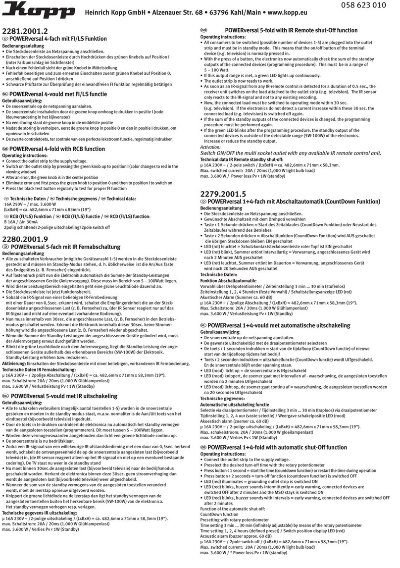
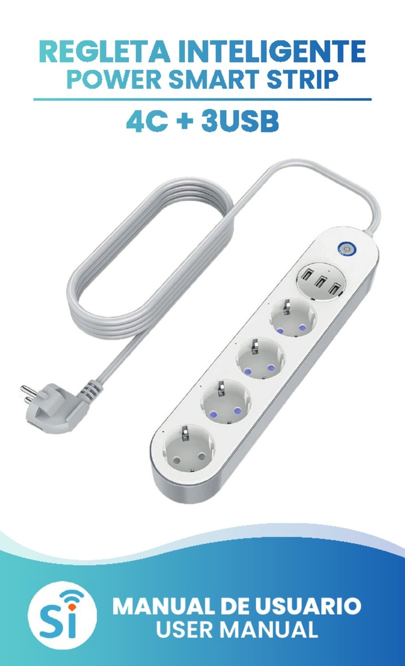
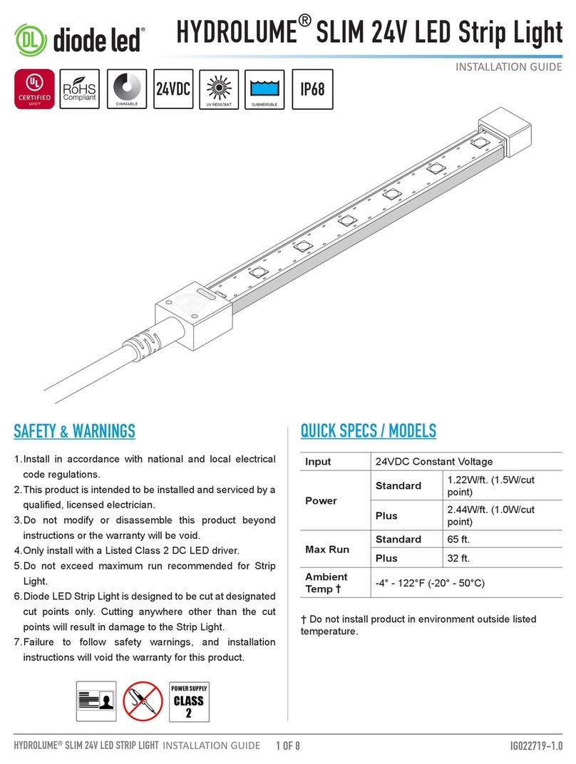
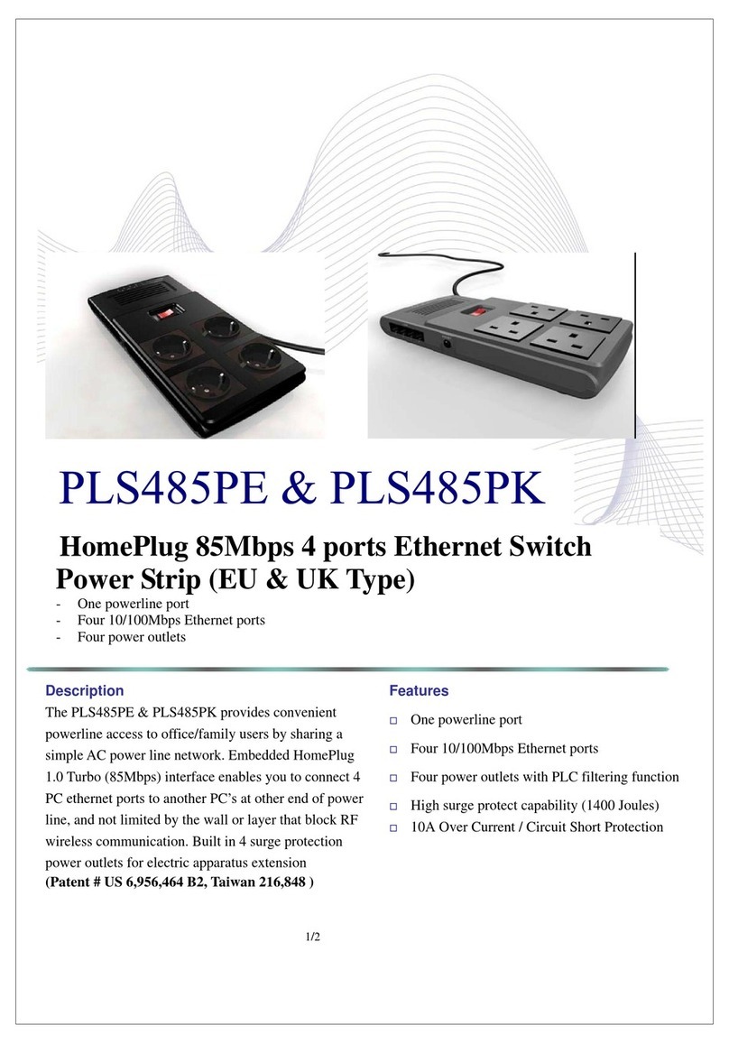
Dataprobe K-4 Series User manual

Technical Support Hotline: (201) 934-5111
Technical Support: 201-934-5111
Website: dataprobe.com
Overview
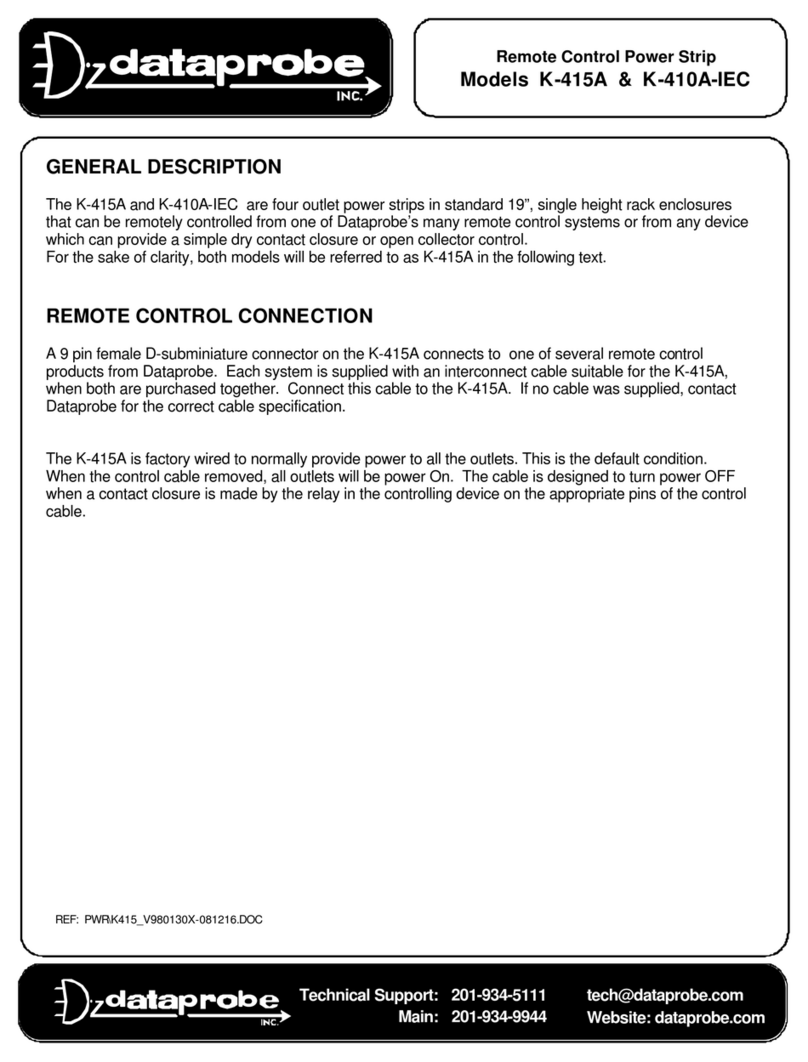
The K-4xx and K-8xx series AC power strips provide multiple switched outlets that can be remotely controlled
from one of Dataprobe’s many remote control systems or from any device providing a contact closure. The
following models are covered in this manual.
K-820 8 switched outlets, for use on 115 VAC, 20 Amp Service –NEMA N5-20
K-420 4 switched outlets, for use on 115 VAC, 20 Amp Service –NEMA N5-20
K-815 8 switched outlets, for use on 115 VAC, 15 Amp Service –NEMA N5-15
K-415 4 switched outlets, for use on 115 VAC, 15 Amp Service –NEMA N5-15
K-810 8 switched outlets, for use on 115/230 VAC, 12 /10 Amp International –IEC 320
K-410 4 switched outlets, for use on 115/230 VAC, 12 /10 Amp International –IEC 320
Throughout this manual the K-815 will be used to represent for all units, except where a distinct
reference is made.
1 2 3 4 Power
1 2 3 4 5 6 7 8 Power
115/230VAC
Selector Switch
On Side
Front Panel
All 8 Outlet Versions
Outlet Status and Power Input Status LEDs
Front Panel
All 4 Outlet Versions
Outlet Status and Power Input Status LEDs
K-820 & K-815, 115VAC
8 NEMA Outlets Switched
K-420 & K-415, 115VAC
4 NEMA Outlets Switched
K-810 , 115 / 230 VAC
8 IEC 320 Outlets Switched
K-410 , 115 / 230 VAC
4 IEC 320 Outlets Switched
Remote Control Power Strip
Models K-820, K-815, K-810
K-420, K-415 & K-410
REF: PWR\K8xx_UL_V020523D.DOC

IMPORTANT SAFETY INSTRUCTIONS
When using this product, basic safety precautions should always be followed to reduce the risk of fire,
electric shock, and injury to persons, including the following:
1. Read and understand all instructions.
2. Follow all warnings and marked on the product.
3. Unplug this product from the wall outlet before cleaning. Do not use liquid cleaners or aerosol
cleaners. Use a damp cloth for cleaning.
4. Do not use this product in an outdoor environment or near water, for example, near a bath tub,
wash bowl, kitchen sink, or laundry tub, in a wet basement, or near a swimming pool.
5. Do not place this product on an unstable cart, stand, or table. The product may fall, causing
serious damage to the product.
6. Slots and openings in this product and the back or bottom are provided for ventilation to protect
it from overheating, these openings must not be blocked or covered. The openings should never
be blocked by placing the product on the bed, sofa, rug, or other similar surface. This product
should never be placed near or over a radiator or heat register. This product should not be placed
in a built-in installation unless proper ventilation is provided.
7. This product should be operated only from the type of power source indicated on the marking
label. If you are not sure of the type of power supply to your home, consult your dealer or local
power company.
8. This product is equipped with a three wire grounding type plug, a plug having a third (grounding)
pin. This plug will only fit into a grounding type power outlet. This is a safety feature. If you are
unable to insert the plug into the outlet, contact your electrician to replace your obsolete outlet. Do
not defeat the safety purpose of the grounding type plug. Do not use a 3-to-2 prong adapter at
the receptacle; use of this type adapter may result in risk of electrical shock and/or damage to this
product.
9. Do not allow anything to rest on the power cord. Do not locate this product where the cord will
be abused by persons walking on it.
10. Do not overload wall outlets and extension cords as this can result in the risk of fire or electric
shock.
11. Never push objects of any kind into this product through slots as they may touch dangerous
voltage points or short out parts that could result in a risk of fire or electrical shock. Never spill
liquid of any kind on the product.
12. To reduce the risk of electrical shock, do not disassemble this product, but take it to a qualified
serviceman when some service or repair work is required. Opening or removing covers may
expose you to dangerous voltages or other risks. Incorrect re-assembly can cause electric shock
when the appliance is subsequently used.
13. Unplug this product from the wall outlet and refer servicing to qualified service personnel under the
following conditions:
a) When the power supply cord or plug is damaged or frayed.
b) If liquid has been spilled into the product.
c) If the product has been exposed to rain or water.
d) If the product does not operate normally by following the operating instructions. Adjust
only those controls, that are covered by the operating instructions because improper
adjustment of other controls may result in damage and will often require extensive work by
a qualified technician to restore the product to normal operation.
e) If the product has been dropped or has been damaged.
f) If the product exhibits a distinct change in performance.
14. Avoid using a telephone (other than a cordless type) during an electrical storm. There may be a
remote risk of electric shock from lightning.
15. Do not use the telephone to report a gas leak in the vicinity of the leak.
16. Do not exceed the maximum output rating of the auxiliary power receptacle.
SAVE THESE INSTRUCTIONS

Series K-x20, K-x15 & K-x10 Page 3
Remote Control and Feedback
Two 9 pin female D-subminiature connector on the K-8xx series are used for connecting to the control
and status feedback. The K-4xx series has only one 9 pin d-subminiature connector and is supplied
with a cable for controlling it with one of Dataprobe’s xPal-4xx series power switches. This cable
enables xPal-4xx unit to expand from 4 controlled outlets to 8.
The wiring for the control port is identical onall units. The K-4xx series only uses Control and
Feedback #s 1 –4 See Wiring detail below. . If your controller does not use this cable, you will need
to build one or order an additional cable from Dataprobe. Refer to the control wiring details below for
cable specification.
The K-815 is factory wired to normally provide power to all the outlets. This is the default condition.
When the control cable removed, all outlets will be power On. The cable is designed to turn power
OFF when a contact closure is made by the relay in the controlling device on the appropriate pins of
the control cable.
A positive feedback system is provided to insure that power control commands are achieved. A
feedback circuit for each outlet provides a Low (ground) condition to indicate that power is On. An
Open condition indicates power Off.
CONTROL WIRING: 9 pin female D-subminiature
Contact Closure between Control to Com = Power OFF
CONTROL # PIN # FEEDBACK# PIN #
J1/J2
1/5 116
2/6 227
3/7 338
4/8 449
COM 5COM 5
Example: To turn off outlet number one, connect the Control (Pin 1) to the Common (Pin 5). The
feedback on Pin 6 will change from Low (shorted to Pin 5) to Open.
Standard Connections to Dataprobe Control Products
Controlled by: Cables Required
iP-410, -415, -420 #1940052, Included w/ K-410, -415, -420 if ordered together
Cp-410, -415,-420 #1940052, Included w/ K-410, -415, -420 if ordered together
MP-410 ,-415,-420 #1940052, Included w/ K-410, -415, -420 if ordered together
iPAL, CodePAL, MultiPAL # 1940046 Qty 1 for K-4xx, Qty 2 for K-8xx series
8PK-SCS # 1940046 Qty 1 for K-4xx, Qty 2 for K-8xx series
ANN, MAC or EMAC # 1940048

Series K-x20, K-x15 & K-x10 Page 4
Power Input and Output Connections
CAUTION Be sure to check that the unit is set to the correct operating voltage before plugging in the
unit or applying AC power. Make certain to disconnect the K-81x from the AC power source before
making any control connections.
A/C Power Connections
The K-820 & K-420 provide a linecord for connection to a 20 Amp 115VAC service. The total maximum current
load for all outlets on the K-820 or K-420 cannot exceed 16 Amps.
The K-815 & K-415 provide a linecord for connection to a 15 Amp 115VAC service. The total maximum current
load for all outlets on the K-815 or K-415 cannot exceed 12 Amps.
The K-810 & K-410 are for international applications and can be set for use on 115V or 230VAC. The K-810 &
K-410 provide an IEC 320 style universal inlet for connecting a detachable power cord. A standard IEC to
NEMA 5-15 cord set is supplied with the unit for use on 15 Amp 115VAC service. The total maximum current
load for all outlets cannot exceed 12 Amps at 115VAC or 10 Amps when used at 230VAC.
The K-810 & 410 are selectable for 115VAC or 230 VAC operation. The voltage selector switch is
located on the left side of the unit near the input connector ( Viewed from rear panel). Make sure the
switch is in the proper position before applying power.
The K-810 uses IEC320 connectors for the switched output. Dataprobe offers IEC to IEC jumper
cables to assist in connection to PC, Router, etc that has IEC Connection
Order Cable
921-14-0016 IEC to IEC 3' long
921-14-0018 IEC to IEC 6' long

Series K-x20, K-x15 & K-x10 Page 5
C
R
SPECIFICATIONS
Physical
19” wide x 6.25” deep x 1.75” high, EIA Rack Mount -1RU
Weight: 5 Lbs.
INDICATORS: Power : On = Power applied to the unit
1 -8 On = Power on to outlet specified
Power
Model K-820 & K-420 110 -120VAC 60 Hz, 16A Max
Model K-815 & K-415 110 -120VAC 60 Hz, 12A Max
Model K-810 & K-410 Switch Selectable ;110-120VAC 50-60Hz, 12A Max
210-240VAC 50-60 Hz, 10A Max
Power Connections
K-820 & K-420
Main Power Input: NEMA 5-20 Plug on 6 foot 12/3 line cord
Output Circuits: Standard NEMA 5-15 Receptacle
Current Maximums: 12 Amps per Receptacle
16 Amps combined total of all receptacles
K-815 & K-415
Main Power Input: Standard NEMA 5-15 Plug on 6 foot 14/3 line cord -120VAC
Output Circuits: Standard NEMA 5-15 Receptacle
Current Maximums: 12 Amps per Receptacle
12 Amps combined total of all receptacles
K-810 & K-410
Select the proper voltage, 115V or 230 V, using the selector switch on the side of the unit before
making power connection
Main Power Input: IEC 320 Male Connector -115/230 VAC Selectable
Output Circuits: IEC 320 Receptacle
Current Maximums: 12 Amps per Receptacle @ 115VAC
10 Amps per Receptacle @ 230VAC
12 Amps combined total of all receptacles @ 115VAC
10 Amps combined total of all receptacles @ 230VAC

Series K-x20, K-x15 & K-x10 Page 6
TECHNICAL SUPPORT, RETURNS and WARRANTY
Dataprobe Technical Support is available 8:30AM to 5:30PM ET to assist you in the installation and
operation of this product. To obtain Technical Support call our Tech Support Hotline at 201-934-5111,
•Model of Product
•Serial Number
•Dateof Purchase
•Name of Seller (if other than Dataprobe)
If you purchased this product through an Authorized Dataprobe Reseller, you should contact them
first, as they may have information about the application that can more quickly answer your questions.
WARRANTY
Seller warrants this product, if used in accordance with all applicable instructions, to be free from
original defects in material and workmanship for a period of One Year from the date of initial purchase.
If the product should prove defective within that period, Seller will repair or replace the product, at its
sole discretion.
Service under this Warranty is obtained by shipping the product (with all charges prepaid) to the
address below. Seller will pay return shipping charges. Call Dataprobe Technical Service at (201)
934-5111 to receive a Return Materials Authorization (RMA) Number prior to sending any equipment
back for repair. Include all cables, power supplies and proof of purchase with shipment.
THIS WARRANTY DOES NOT APPLY TO NORMAL WEAR OR TO DAMAGE RESULTING
FROM ACCIDENT, MISUSE, ABUSE OR NEGLECT. SELLER MAKES NO EXPRESS
WARRANTIES OTHER THAN THE WARRANTY EXPRESSLY SET FORTH HEREIN. EXCEPT
TO THE EXTENT PROHIBITED BY LAW, ALL IMPLIED WARRANTIES, INCLUDING ALL
WARRANTIES OF MERCHANT ABILITY OR FITNESS FOR ANY PURPOSE ARE LIMITED TO
THE WARRANTY PERIOD SET FORTH ABOVE; AND THIS WARRANTY EXPRESSLY
EXCLUDES ALL INCIDENTAL AND CONSEQUENTIAL DAMAGES.
Some states do not allow limitations on how long an implied warranty lasts, and some states do not
allow the exclusion or limitation of incidental or consequential damages, so the above limitations or
exclusions may not apply to you. This warranty gives you specific legal rights, and you may have
other rights which vary from jurisdictions to jurisdiction.
WARNING: The individual user should take care to determine prior to use whether this device is
suitable, adequate or safe for the use intended. Since individual applications are subject to great
variation, the manufacturer makes no representation or warranty as to the suitability of fitness for any
specific application.
This manual suits for next models
7
Table of contents
Other Dataprobe Power Strip manuals
Popular Power Strip manuals by other brands
Reelcraft Industries, Inc.
Reelcraft Industries, Inc. LG3040 123 9 operating instructions
Tripp Lite
Tripp Lite TLM615NC Specification sheet
Tripp Lite
Tripp Lite PS410HGUK owner's manual
Tripp Lite
Tripp Lite UL603CB-6 manual
Tripp Lite
Tripp Lite Surge Protector user manual
Tripp Lite
Tripp Lite UL24CB-15 Specifications
