Datawell 4A User manual

Datawell GPS Buoy Finder
Type 4A
Manual
from serial no.: 41226
August 21, 2013
Service & Sales
Voltastraat 3
1704 RP Heerhugowaard
The Netherlands
+31 72 534 5298
+31 72 572 6406
www.datawell.nl

2

3
Contents
1 Introduction ................................................................................................... 5
2 Front- and back-panel layout ....................................................................... 7
3 Operation ....................................................................................................... 9
3.1 Antenna.................................................................................................... 9
3.2 Power switch............................................................................................ 9
3.3 Display ..................................................................................................... 9
3.4 Buoy Finder 4A display messages......................................................... 10
3.4.1 Synchronization .............................................................................. 10
3.4.2 Gps messages................................................................................ 10
3.4.3 Heave ............................................................................................. 11
3.4.4 Bit errors ......................................................................................... 11
3.5 Speaker.................................................................................................. 12
3.6 Menu functions and programming.......................................................... 12
3.6.1 Activating the menu function........................................................... 12
3.6.2 Menu structure and control ............................................................. 13
3.6.3 Changing the receiver mode........................................................... 15
3.6.4 Changing the frequency.................................................................. 15
3.6.5 Memory functions............................................................................ 15
3.6.6 Info functions and signal quality monitoring .................................... 18
4 Battery replacement and troubleshooting ................................................ 21
4.1 Battery power and replacement ............................................................. 21
4.2 Antenna, signal quality and noise........................................................... 22
5 Specifications.............................................................................................. 23
Appendix A: Datawell Sales and Service Addresses.................................. 25

4

5
1 Introduction
Welcome to the Buoy Finder 4A manual.
The Datawell Buoy Finder 4A is designed to facilitate the retrieval of lost or drifting Datawell
buoys. The Buoy Finder 4A is based on the RX-C Waverider receiver but is enhanced for more
reliable decoding of the GPS position. The Buoy Finder 4A uses a splash water resistive
housing.
The Buoy Finder 4A is an advanced HF link portable receiver that can receive all Datawell
Waverider buoys using the HXV or HVA transmission format. The HXV format is transmitted
by the MkI, MkII and MkIII generations of buoys. The MkIII generation includes the WR-SG,
the DWR-MkIII and the DWR-G. The HVA format is transmitted by the “4-series” generation
of buoys. This includes the DWR4 and the GPS-DWR4. This manual covers Buoy Finder 4A’s
from the serial number shown on the cover. Older Buoy Finder 4’s do not support the HVA
format and are not covered in this manual. It’s possible however to upgrade your Buoy Finder 4
to a Buoy Finder 4A.
The new Buoy Finder 4A is equipped with synthesizer tuning which makes it possible to tune
exactly into a buoy frequency without the need to change the receiving crystal. Also up to 6
buoy frequencies can be stored into its memory.
In Chapters 2 and 3 of this manual the installation and operation of the Buoy Finder 4A are
described. Chapter 4 is about battery replacement and troubleshooting in case of bad or no
reception while Chapter 5 contains the specifications of the Buoy Finder 4A.
Finally the Datawell contact addresses can be found in Appendix A.
Important: check if the Buoy Finder 4A is compliant with the buoy you want to receive.
Check receiver mode:
HXV mode for DWR MKII, III, DWR-G and WR-SG
HVA mode for DWR4
See chapter 3.6.3

6

7
2 Front- and back-panel layout
The front panel of the Buoy Finder 4A contains the following components:
•Antenna connector.
•Headphone connector.
•LCD (liquid crystal display).
•Up / volume switch ( ▲).
•Menu / select switch ( ).
•Down / on/off switch ( T).
The back panel contains the battery compartment and the serial number plate.

8

9
3 Operation
This chapter describes the operation and programming of the Buoy Finder 4A. It is assumed that
the receiver is connected properly to an antenna. Information on how to replace the batteries can
be found in Chapter 4.
3.1 Antenna
The Buoy Finder 4A comes with a small whip antenna. This antenna is designed for outdoor use
only. It will not or badly work inside a building or a boat. If the Buoy Finder 4A is to be used
indoors or on a location with bad reception, the antenna should be relocated by using a coaxial
cable and a magnetic antenna foot. These are available as an option. Contact Datawell sales for
more details.
3.2 Power switch
Pushing the “power” button once will switch the Buoy Finder 4A on. Holding this button will
switch it off, unless the menu is activated. After power up, the receiver will be trying to receive
a buoy1, which can be seen on the LCD display showing the “synchronizing” message.
If the buoy frequency matches the receive frequency the receiver will respond as described in
Paragraph 3.4. If the receive frequency does not match the buoy’s transmission frequency the
Buoy Finder 4A should first be set to the transmit frequency of the buoy. This will be explained
in Paragraph 3.6, which also treats the other functions of the menu.
3.3 Display
Figure 3.1. The three sections of the Buoy Finder 4A display in decode mode.
The operational screen of the Buoy Finder 4A is divided in 4 sections:
•Main
The main section shows synchronization state, the heave, GPS position, age of GPS
position (HXV mode) or UTC time of last GPS position (HVA mode), the volume of the
speaker, error messages or the “hold for menu” message, depending on the current
operating mode.
1At power up its receive frequency is the last receive frequency which was stored into the non volatile
memory of the Buoy Finder 4A, see also the note at the end of paragraph 3.7.3.

10
•Signal
The signal section shows the signal strength of the received buoy in logarithmic scale. A
full-scale deflection of the bar graph corresponds with an input signal of -50 dBm or
more, an empty bar graph corresponds with an input signal of -90 dBm or less. For
signals weaker than -90 dBm the audio signal should be used to get an indication of the
signal strength of the input signal.
•Battery
The battery indication shows the status of the batteries.
indicates full batteries, almost empty batteries.
3.4 Buoy Finder 4A display messages
The following paragraphs describe the behaviour of the receiver and the meaning of the
messages in the main part of the display. After power up, the receiver is set to synchronize
mode.
Synchronization
At start-up or after signal loss, the Buoy Finder 4A will try to lock in to a buoy signal. The
synchronization process is necessary to make sure that the receiver is properly aligned to the
RF-signal and to the vector boundaries of the buoy’s data pattern. The synchronization process
is indicated by two messages on the receiver’s display:
“synchronizing”The receiver has lost vector synchronization and is waiting for a valid
sync-word to indicate the beginning of a new frame.
“checking sync”The receiver has reached vector synchronization and is currently
double-checking the vector boundary’s.
Normally, after power up or loss of signal, the receiver will display “synchronizing” for some
time and then will display “checking sync”. After the Buoy Finder 4A has double checked the
vector synchronization it will search for a GPS position and display the heave. If a valid GPS
position is found, the Buoy Finder 4A will also show this position.
NOTE:
The process of synchronization can take anything between 30 seconds to several minutes.
The time needed to reach frame-synchronization depends on several factors like signal strength,
interference, noise bursts and type of buoy. During the synchronization it is possible that the
message switches several times between “synchronizing” and “checking sync”.
If synchronization has been established some of the received data will be displayed in the main
part of the display.
3.4.1 Gps messages
The GPS position is displayed in the three messages, one for latitude:
lat: DDºMM.FFFH
H: N for northern hemisphere, S for southern hemisphere
DD: 0-90 degrees.
MM: 0-59 minutes
FFF: 0-999 1/1000 minutes.
example: lat: 52º22.080N

11
one for longitude:
lon: DDºMM.FFFH
H: E for eastern hemisphere, W for western hemisphere
DDD: 0-180 degrees.
MM: 0-59 minutes
FFF: 0-999 1/1000 minutes.
example: lon: 4º37.190E
and one for the age of the position (HXV mode) or UTC time of last position (HVA mode):
fix=DD mins old (HXV mode)
DD: 0-99 minutes.
fix=HH:MM UTC (HVA mode)
HH: 0-24 hours.
DD: 0-59 minutes.
The Buoy Finder 4A continuously searches for newer GPS positions in the incoming data.
When a new GPS position is found, the position is updated.
In HXV mode, the time elapsed (“age”) of the received buoy position is displayed in minutes.
The age is referenced to the beginning of the transmission. It is not referenced to the time of
acquisition. Please refer to the manual of the buoy for the time of acquisition relative to the start
of a transmission. Normally, because a new position is sent every 30 minutes and receiving a
position takes 4-6 minutes, the age of the position does not exceed 36 minutes.
If the age of the last found position exceeds 60 minutes, the Buoy Finder 4A removes this
position from its memory and will not show it anymore.
In HVA mode, the UTC time of the last received position is given. The GPS position fix will be
updated every 10 minutes.
3.4.2 Heave
The momentary heave that is received is also displayed between the messages of the GPS
position and continuously when the receiver has not yet received a GPS position.
The format is:
heave: DDDD cm
DDDD:0-9999 cm.
3.4.3 Bit errors
When a vector (64 bit data part) is received with errors, the receiver shows the message:
bad vector

12
3.5 Speaker
The speaker is mainly used to get an indication of the signal quality. A 1500 Hz frequency
modulated beat-note should be heard against a clean background (none or clean noise without
any sign of interference or noise bursts).
The volume of the speaker can be adjusted by pressing the switch when you are not in
the menu mode and then the ▲or Tbuttons.
3.6 Menu functions and programming
The Buoy Finder 4A receiver is fitted with a built in user interface. This user interface is used to
adjust the receive frequency to a buoy frequency, to store and to recall up to six preset buoy
reception frequencies and to monitor received signal characteristics.
The following paragraphs describe how to navigate through the menu functions.
The buttons used in the menu are (see also chapter 2):
•the up / volume button, indicated by a ▲;
•the menu / select button, indicated by a ;
•the down / on/off button, indicated by a T.
3.6.1 Activating the menu function
To activate the menu function2, push the “ ” button and the LCD shows the “hold for menu”
message in its “main” area.
After a few seconds of holding the “ ” button the display text changes from the receive mode
text into the following menu text:
Figure 3.2. The menu function mode with the function EXIT selected.
From here we are able to access the memory and info functions, to change the receive frequency
and / or to go back to the “receive mode” display text by using the “▲”, “” and “T” buttons.
2Entering the menu function does not influence the receiving and the decoding functions of the Buoy
Finder 4A, the receiver will continue to update the decoded position data.

13
3.6.2 Menu structure and control
We will first show how the menus are organised:
Figure 3.3. Organization of the menu structure.
By using the “▲”, “” and “T” buttons we are able to control the menu functions.
The menu starting screen is depicted in figure 3.2. The exit function is highlighted by using
capitals and brackets “[EXIT]”.
If we now would push the “ ” ( = select) button the exit function is activated and we would
leave the menu and return to the normal receive mode screen of figure 3.1.
Pressing the “T” knob once will select the hxv or hva mode function. We have to press the
select button “ ” to change between the two receiver modes. This submenu will be explained
in paragraph 3.6.3.
Figure 3.4. Selection of HXV or HVA mode function
Menu
mem
info
store
recall
set fre
q
uenc
y
p
reset number
p
reset number
si
g
nal status
batter
y
volta
g
e
actual fre
q
uenc
y
current vector
hxv/hva set hxv or hva
mode

14
Pressing the “T” knob again will select the second digit (steps of one MHz,) of the frequency
adjustment function, this is depicted in figure 3.5 with an underlined number “ 0”:
Figure 3.5. Selection of the 1 MHz steps digit of the frequency change function
indicated by an underlined number 0.
Selecting and deselecting the digit is done with the “ ” button, selecting the other digits is
possible pressing the “T” knob for the next digit (or function) or pressing the “▲” knob for the
former digit (or function).
For example, when starting from the clean menu screen of figure 3.2 we have to press the “T”
button six times or the “▲” knob two times to select the mem (memory) function as is shown in
figure 3.6.
Figure 3.6. Selection of the mem (= memory) function.
We have to press the select button “ ” to enter the mem submenu. This submenu will be
explained in paragraph 3.6.5.
To select the info function from the menu screen of figure 3.3 with [EXIT] selected we have to
press the “▲” knob one time or the “T” button seven times. The selected info submenu is
shown in figure 3.7:
Figure 3.7. Selection of the info function.
Pressing the select button “ ” now brings us into the info submenu. This submenu will be
explained in paragraph 3.6.6.
The next subparagraphs will describe the control and monitoring functions in the menu in detail
with a step by step approach.

15
3.6.3 Changing the receiver mode
The Buoy Finder 4A can receive data in the HXV format and in the HVA format. The HXV
format is transmitted by the MkI, MkII and MkIII generations of buoys. The MkIII generation
includes the WR-SG, the DWR-MkIII and the DWR-G. The HVA format is transmitted by the
“4-series” generation of buoys. This includes the DWR4 and the GPS-DWR4.
To change the receiver mode, select the “hxv” or “hva” menu item on the top menu. Press the
button to change the receiver mode. Possible choices are HXV and HVA.
To save the new receiver mode to non-volatile memory, be sure to properly exit the top menu.
3.6.4 Changing the frequency
Step 1. From the receive mode first enter the menu function by pressing the “ ”
button a few seconds, figure 3.2.
Step 2. Press the “T” button once so that the second digit (thus in steps of one MHz) of
the frequency is selected for adjustment, figure 3.4.
Step 3. Select the one MHz step digit by pressing the “ ” button, the digit now starts
blinking and the speaker will be switched on so that the signal on the current
frequency can be heard.
Step 4. Press the “T” or “▲” button until the digit matches with the transmit frequency.
Step 5. Deselect the digit by pressing the “ ” button, the digit now stops blinking and
the speaker will be switched off.
Step 6. Proceed with selecting and changing the next digits (in 100 kHz, 10 kHz, 1 kHz,
100 Hz steps) by using the “T” or “▲” buttons and following the procedure as
described for the first digit in the steps 3, 4 and 5.
Step 7. Use the “T” or “▲” buttons to go back to the exit menu (figure 3.2) and press
the “ ” button to go back to the normal receive mode or proceed with the mem
or info submenu, for instance for storing the current frequency into a preset
(described in paragraph 3.6.5).
Note:
The frequency change will be stored in non volatile memory only when you have gone back
from the menu mode (figure 3.2) into the receive mode (figure 3.1) after this procedure !!!
3.6.5 Memory functions
There are two functions in the memory submenu, namely the store function in which a
frequency can be stored into a preset, and the recall function which can recall an already stored
preset.
Storing a frequency into a preset
Step 1. From the receive mode first enter the menu function by pressing the “ ”
button a few seconds.
Step 2. Make sure that the frequency in the display (figure 3.2) is the frequency which
you want to be stored into a preset. If not adjust the frequency displayed as
described in paragraph 3.6.3.

16
Step 3. Press the “▲” button twice so that the mem submenu is selected (figure 3.6).
Step 4. Push the “ ” button and the memory submenu is shown (figure 3.8).
Figure 3.8. Display from the mem submenu.
Step 5. Select the sto (store) function by pressing the “T” button once (figure 3.9).
Figure 3.9. Selecting the store function in the mem submenu.
Step 6. Press the “ ” button to enter the store preset menu (figure 3.10).
Figure 3.10. The store preset display.
Step 7. Proceed with selecting the preset number (in figure 3.9 indicated with the
underlined 1) by using the “T” or “▲” buttons. Up to six preset frequencies can
be stored.
Step 8. Use the “ ” button to confirm your selection of the preset number. The old
preset value will be overwritten and the display from figure 3.11 will be shown
for two seconds before returning to the main menu of figure 3.2.
Figure 3.11. Message after confirming a preset store command.
Step 9. Go back to the normal display of figure 3.1 by pressing the “ ” button in order
to save the stored preset(s) into non volatile memory.

17
Recalling a frequency from a preset
Step 1. From the receive mode first enter the menu function by pressing the “ ”
button a few seconds.
Step 2. Press the “▲” button twice so that the mem submenu is selected (figure 3.7).
Step 3. Hit the “ ” select button and the memory submenu is shown (figure 3.9).
Step 4. Select the rcl (recall) function by pressing the “▲” button once (figure 3.12).
Figure 3.12. Selecting the recall function in the mem submenu.
Step 5. Press the “ ” button to enter the recall preset menu (figure 3.13).
Figure 3.13. The recall preset display.
Step 6. Proceed with selecting the preset number (in figure 3.13 indicated with the
underlined 1) by using the “T” or “▲” buttons. Up to six preset frequencies can
be selected.
Step 7. Use the “ ” button to confirm your selection of the preset number. Now the
display from figure 3.14 will be shown for two seconds before returning to the
main menu of figure 3.2.
Figure 3.14. Message after confirming a preset recall command.
Step 8. Go back to the normal display of figure 3.1 by pressing the “ ” button.

18
3.6.6 Info functions and signal quality monitoring
Four displays with parameters from the receiver can be displayed, namely the actual receive
frequency, the signal status, the battery status and the current vector. These will be described
below.
Actual frequency display
The actual frequency display shows the frequency to which the receiver is tuned with a
resolution of 1 Hz. This information might be valuable when troubleshooting.
Figure 3.15. Displaying the actual receive frequency.
The actual frequency display can be accessed as follows:
Step 1. From the receive mode first enter the menu function by pressing the “ ”
button a few seconds.
Step 2. Press the “▲” button once so that the info submenu is selected (figure 3.7).
Step 3. Hit the“ ” select button and the actual frequency is shown (figure 3.15).
Step 4. Press the “ ” button twice to return to the normal receive mode display of
figure 3.1.
Signal status display
The signal status display gives us an average Frame Error Rate (FER)3and Instantaneous
Frequency Deviation (IFD). The FER gives us an indication of the quality of the received
signal, while the IFD might be used in the case when strong RF interferers mess up the received
signal. Their purpose is thus mainly for troubleshooting.
Figure 3.16. Displaying the signal status, the frame error rate (FER) is 3 %,
the instantaneous frequency deviation is -11 Hz.
3The FER is averaged over 128 frames, thus over 100 seconds. The FER is the percentage of frames
which contain an error.

19
The signal status display can be accessed as follows:
Step 1. From the receive mode first enter the menu function by pressing the “ ”
button a few seconds.
Step 2. Press the “▲” button once so that the info submenu is selected (figure 3.7).
Step 3. Hit the “ ” button and the actual frequency is shown (figure 3.15).
Step 4. Press the “T” button once and the signal status is shown (figure 3.16).
Step 5. Pressing the “ ” button twice returns you to the normal receive mode display
of figure 3.1.
Battery status display
The battery status display shows the voltage of the batteries. If the voltage is 2.1 V or less the
receiver will only work for some hours.
Figure 3.17. Displaying the battery voltage.
The battery status display can be accessed as follows:
Step 1. From the receive mode first enter the menu function by pressing the “ ”
button a few seconds.
Step 1. Press the “▲” button once so that the info submenu is selected (figure 3.7).
Step 2. Hit the “ ” button and the actual frequency is shown (figure 3.15).
Step 3. Press the “T” button twice and the battery voltage is shown (figure 3.17).
Step 4. Pressing the “ ” button twice returns you to the normal receive mode display
of figure 3.1.

20
Current vector display
The current vector display shows the last decoded vector. Those vectors contain the information
received from the buoy such as the GPS position information of the buoy.
Figure 3.18. Displaying the current vector.
The current vector display can be accessed as follows:
Step 1. From the receive mode first enter the menu function by pressing the “ ”
button a few seconds.
Step 2. Press the “▲” button once so that the info submenu is selected (figure 3.7).
Step 3. Hit the “ ” button and the actual frequency is shown (figure 3.15).
Step 4. Press the “T” button three times and the current vectors are shown (figure 3.18).
Step 5. Pressing the “ ” button twice returns you to the normal receive mode display
of figure 3.1.
Table of contents
Popular GPS manuals by other brands
Garmin
Garmin STRIKER Series owner's manual
Holux
Holux GPSPORT 245 BIKE - user guide
elsner elektronik
elsner elektronik Vari KNX GPS Technical specifications and installation instructions

Extra Miles
Extra Miles UTRACK MVT600 user guide

I-gotU
I-gotU GT-900 Series user manual
GalileoSky
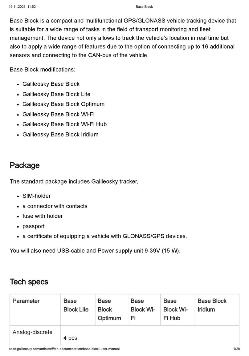
GalileoSky Base Block manual

