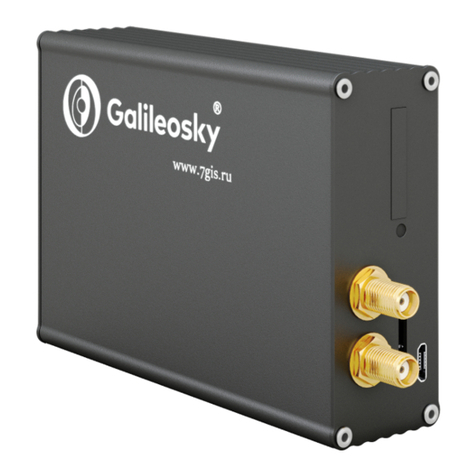
GalileoSky Base Block User manual

19.11.2021, 11:52
Base Block
base.galileosky.com/articles/#!en-documentation/base-block-user-manual
1/28
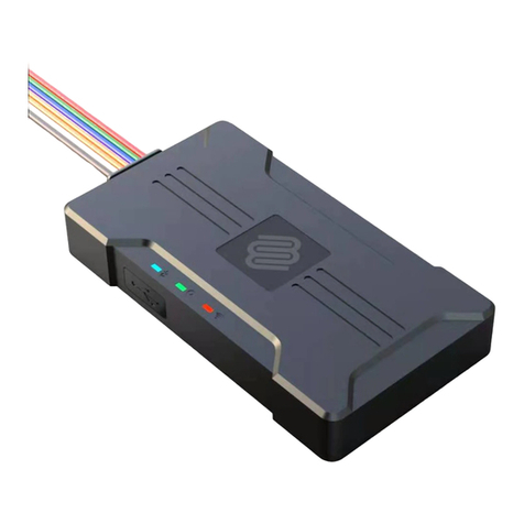
Base Block is a compact and multifunctional GPS/GLONASS vehicle tracking device that
is suitable for a wide range of tasks in the field of transport monitoring and fleet
management. The device not only allows to track the vehicle’s location in real time but
also to apply a wide range of features due to the option of connecting up to 16 additional
sensors and connecting to the CAN-bus of the vehicle.
Base Block modifications:
Galileosky Base Block
Galileosky Base Block Lite
Galileosky Base Block Optimum
Galileosky Base Block Wi-Fi
Galileosky Base Block Wi-Fi Hub
Galileosky Base Block Iridium
Package
The standard package includes Galileosky tracker,
SIM-holder
a connector with contacts
fuse with holder
passport
a certificate of equipping a vehicle with GLONASS/GPS devices.
You will also need USB-cable and Power supply unit 9-39V (15 W).
Tech specs
Parameter Base
Block Lite
Base
Block
Optimum
Base
Block Wi-
Fi
Base
Block Wi-
Fi Hub
Base Block
Iridium
Analog-discrete
4 pcs;

19.11.2021, 11:52
Base Block
base.galileosky.com/articles/#!en-documentation/base-block-user-manual
2/28
and pulse
frequency inputs
voltage range -0-33V;
maximum measured frequency-4 kHz
Transistor
outputs (output
0/1)
2 pcs.; maximum voltage 30V; maximum current 80mA.
Battery type Li-Ion
battery;
600mAh
Average power
consumption
0,48 W 0,54 W 0,6 W 0,6 W 0,6 W
ADC resolution in
bits
16
CANBUS J1939, FMS, J1979, OBD II, 29-bit and 11-bit identifiers
RS 485 1
USB 2.0 Micro-USB, device setting, troubleshooting, firmware updating
Accelerometer built-in
GLONASS/GPS
receiver
Sensitivity – 161 dBm
Cold start 25 s.;
Hot start 1 s
Coordinates
determination
accuracy, 95% of
time, not worse
5 m
SIM-card type,
pcs
Micro-SIM, 1
GSM modem GSM 850/900/1800/1900, GPRS class 12

19.11.2021, 11:52
Base Block
base.galileosky.com/articles/#!en-documentation/base-block-user-manual
3/28
Wi-Fi no no IEEE 802.11 b/g/n no
Iridium no yes
Archive capacity
up to
400 000
points
up to 2 500 000 points for each GB by using the micro
SD card
1-Wire yes
RS 232 no 2 2 2 2
microSD
no up to 64 GB.
It is recommended to use the following micro SD
cards:
Transcend slc mode 230i 8 (TS8GUSD230)
Kingston sdcit/8gb (SDCIT/8GB)
Speakerphone no a push-to-talk or a speaker and a microphone
Speaker
(Autoinformer)
no built-in
The number of
geofences for
voice prompts
no limited by microSD capacity
Frequency of
autoinformer
discretization
no
8kHz 8kHz 16kHz 8kHz
Speaker output
type
no
analog, 250mW
Enhancement By means of creating Easy Logic algorithms, stored in the tracker’s
memory and executed with no interference with the firmware
Protocol of data
1. Galileosky: variable length-tag.

19.11.2021, 11:52
Base Block
base.galileosky.com/articles/#!en-documentation/base-block-user-manual
4/28
transmission 2. EGTS (GOST R 54619-2011, Order № 285 of the RF Ministry
of Transportation)
Enclosure
protection
IP54
GLONASS/GPS
aerial
external, Fakra
GSM aerial external, Fakra
Wi-Fi aerial no no external external no
Iridium aerial no external
Operating
temperature
range
-40…+85 °C
Storage
temperature
-40…+85 °C
Relative humidity 0…90% (0…35 °C); 0…70% (35…55 °C)
Performance
(height above the
sea level)
0-2000 m
Storage 0-10000 m
Operating power
supply
9-39V; is protected against voltage jumps in the vehicle power
supply
Allowable voltage -900…+200 V – continuously applied to power input, that does not
let the device fail
Dimensions (mm) 80 x 71 x
28
80 х 71 х 40
Weight (not
more)
150 g 215 g
Body material metal

19.11.2021, 11:52
Base Block
base.galileosky.com/articles/#!en-documentation/base-block-user-manual
5/28
Contact Description
Average service
life
10 years
Warranty (from
date of purchase)
5 years 2 years
Internal Li-Ion
battery life
500 charge/discharge cycles, three years maximum
Safe Operating Rules
Before using the tracking device, study the instructions of GSM/3G/GPRS devices safe
operating.
Make sure the polarity is correct when connecting to the power supply.
The device should be connected straight to the vehicle battery, not to the vehicle power
supply.
To avoid failure:
Make sure the contacts are connected correctly. Unused contacts must be we
Contacts Description

19.11.2021, 11:52
Base Block
base.galileosky.com/articles/#!en-documentation/base-block-user-manual
6/28
VCC Positive supply voltage
GND Negative supply voltage
IN0 Zero analog-discrete input
IN1 1st analog-discrete input
IN2 2nd analog-discrete input
IN3 3rd analog-discrete input
RS485A A signal of RS485 channel
RS485B B signal of RS485 channel
RXD0 RXD signal of zero RS232 port (only for Optimum/Iridium/Wi-Fi/Hub/3G m
TXD0 TXD signal of zero RS232 port (only for Optimum/Iridium/Wi-Fi/Hub/3G m
RXD1 RXD signal of the first RS232 port (only for Optimum/Iridium/Wi-Fi/Hub/3G
modifications)
TXD1 TXD signal of the first RS232 port (only for Optimum/Iridium/Wi-Fi/Hub/3G
modifications)
CAN_H CAN_H contact of CAN interface (only for Optimum/Iridium/Wi-Fi/Hub/3G
CAN_L CAN_L contact of CAN interface (only for Optimum/Iridium/Wi-Fi/Hub/3G
Vol0 Zero contact to connect an external speaker for Autoinformer (only for
Optimum/Iridium/Wi-Fi/Hub/3G modifications)
Vol1 First contact to connect an external speaker for Autoinformer (only for
Optimum/Iridium/Wi-Fi/Hub/3G modifications)
1-Wire 1-Wire interface
GND Ground to connect interfaces which need the ground contact
Out0 Zero transistor output (output 0/1)
Out1 First transistor output (output0/1)

19.11.2021, 11:52
Base Block
base.galileosky.com/articles/#!en-documentation/base-block-user-manual
7/28
Connecting GLONASS aerial
The top of the aerial must face the sky. To get the best view of the sky, we recommend
installing the aerial on the roof or on the windshield, or under the dashboard of the
vehicle.

19.11.2021, 11:52
Base Block
base.galileosky.com/articles/#!en-documentation/base-block-user-manual
8/28
Blinking of the green LED 1 time means successful reception of a signal from the
satellites.
Connecting GSM/3G-aerial
Position the GSM/3G antenna in such a way that the GSM/3G network signal is not
strongly weakened by the metal housing of the vehicle.
Blinking of the blue LED 1 time means successful connection to the monitoring server.
Connecting Iridium aerial
Carefully screw the aerial to the Terminal, the upper side is above. To have a better view
of the sky it is recommended that the aerial should be mounted on the vehicle roof,
windscreen or under the dashboard.
To provide the proper connection, we recommend that the Iridium antenna is
installed on the horizontal surface at a zero angle to the horizon and with
clear, 360 degrees view of the sky, for example, on the top of the vehicle.
Inserting SIM-card
Insert the SIM cards with the GPRS and SMS services connected. To remove the SIM
card, gently push it in until it clicks and the card automatically slides out of the mobile
computer.
Connecting power supply to the device
Positive supply voltage should be connected to VCC contact, negative supply voltage
should be connected to GND.
If the connection is correct, the red LED will be on.


19.11.2021, 11:52
Base Block
base.galileosky.com/articles/#!en-documentation/base-block-user-manual
9/28
LED indicators
Red LED is on when the power unit is connected to the tracking device.
Yellow LED is on when the microcontroller is running (blinks with the frequency of 1 Hz). It
is also used to indicate the bootloader mode.
Green LED shows the GLONASS/GPS unit status.
Blinking frequency,
times Description
3 GLONASS/GPS unit is not found or is at the
initialization stage
2 GLONASS/GPS unit is found but correct
coordinates are absent
1 GLONASS/GPS unit works properly, coordinates
are found and updated once a second
Blue LED shows the GSM/3G-unit status.
Blinking frequency,
times Description
3 GSM/3G-unit is not found or is at the
initialization stage
2 GSM/3G-unit is found, GPRS-session is
activated
1 GSM/3G-unit works properly, server is
connected
Connecting to PC
In order to connect the tracking device to PC, use USB A – Micro-USB B.
Using defective cables (with disconnected grounds contacts on connectors) may lead to
device’s failure.

19.11.2021, 11:52
Base Block
base.galileosky.com/articles/#!en-documentation/base-block-user-manual
10/28
Discrete-analog inputs (DAI)
Tracking device has 4 discrete-analog inputs.
Feature Value
Maximum measured voltage 33 V
Analog inputs resolution 1 mV
Maximum transmitted signal
frequency 4 kHz
DAI have the following settings:
Parameter Explanation
Filter type (input
function) 0 - arithmetical average (discrete input
state is also generated);
1 - pulse count;
2 - frequency input;
Filter length to
calculate the mean
value
The greater this parameter, the more
slowly the device responds to the input
signal change. With filter length equal to 1
- averaging does not happen.
Set this parameter to 1 for frequency
inputs.
It is necessary to set this parameter to 1
for pulse inputs. If the tracking device
counts extra pulses, the filter length
should be increased by one and accuracy
should be estimated.

19.11.2021, 11:52
Base Block
base.galileosky.com/articles/#!en-documentation/base-block-user-manual
11/28
Ranges for
response/
nonresponse areas
(logical 1 and 0)
To process discrete signals,
response/nonresponse range should be
set where signals are equal to one and
zero. Discrete inputs states should be
seen in the Status of Inputs field, but not in
the Input voltage field.
While counting pulses or frequency, it is
necessary to put the value equal to half
the pulse value into all the fields of the
given group (example: the pulses'
amplitude is 5000 mV, so all the fields
must take the value 2500 mV)
Pulse count
In case of a renewable counter the maximum pulse number can be 65535, after that the
number is reset to zero.
Mean value and discrete event generation
Example 1.
Let us consider the example with the following zero input setting (see the left-hand figure:
Filter type is 0;
Filter length is 5;
Logical one zone range is 8-33V;
Logical zero zone range is 0-3V.

19.11.2021, 11:52
Base Block
base.galileosky.com/articles/#!en-documentation/base-block-user-manual
12/28
The mean value is calculated continuously and is put into the corresponding field IN0. At
the same time, it is continuously checked whether the calculated value belongs to the
given range.
If it is in the range 8-33V, the corresponding bit will find itself in the Status of Inputs field
and a point will be recorded.
By value coming into the indifference zone 3V-8V, the former bit value will be saved to the
Status of Inputs field.
If the value is in the logical zero zone 0V-3V, the corresponding bit in the Status of Inputs
field is reset.
Thus, we can see that the given bit can change its state only in the logical one/logical
zero zones.
Example 2.
In contrast to example 1 the logical one zone and the logical zero zone have changed
places.
Frequency count
To measure frequency in some sensors it is necessary to connect the sensor frequency
output to the sensor positive power supply via a 1kOhm resistor. Otherwise, frequency
count is impossible.

19.11.2021, 11:52
Base Block
base.galileosky.com/articles/#!en-documentation/base-block-user-manual
13/28
Determination of Strike and Incline
All devices can determine the device`s strike and incline.
To determine strike:
Install the tracking device so as one of the accelerometer axis looks vertically, it will
exclude false detections on road bumps;
Turn on strike and incline determination by SHOCK commanand. For example, if Z
axis is vertical: SHOCK 3,90,5,1200.
A strike is an acceleration increase in horizontal plane; the correspondent bit is put in the
Device state field and strike coordinates are recorded.
To determine incline:
1. Install the tracking device in a vehicle;
2. By SHOCK command set maximum allowable incline angle and allowable time of
this angle exceeding. For example, a maximum angle is 20º, allowable exceed time
is 5 seconds; SHOCK 3,20,5,1200.
On the tracker homing position change in a vehicle, SHOCK command should be given to
adopt the device to a new position.
Data Archiving to the MicroSD Card
The saved data will be ordered in the following way:
X:\Arc\
1.gsa
2.gsa
...
10.gsa
Code

19.11.2021, 11:52
Base Block
base.galileosky.com/articles/#!en-documentation/base-block-user-manual
14/28
…
where X is a disc name of microSD.
If there isn’t enough space on the microSD card, the tracker tries to delete the oldest files
from the Arc folder.
Monitoring Data Transmission
The scheme of of the tracker´s interaction with the server and software:
The tracking device allows specifying the list of preferred GSM/3G-networks.
The tracking device allows data transmission to the main and backup monitoring servers.
The tracker accounts transmitted data separately for each server, thus, both will receive
full archive with the track.
Data can be transmitted according to the Galileosky or EGTS protocol. Algorithm
(http://tomstdenis.tripod.com/xtea.pdf) is used for coding.
The data are archived in the internal flash-memory by default.
Internal Archive Structure
The data archive can be stored in the internal flash memory (by default) or on a microSD
card.

19.11.2021, 11:52
Base Block
base.galileosky.com/articles/#!en-documentation/base-block-user-manual
15/28
Options for storing and sending archive data: first the newest, then the oldest, in the
chronological order.
If the archive is on a microSD card, the data is always sent in chronological order.
Operation with SIM-microchip
Applicable for modifications Optimum/Iridium/WI-FI/Hub only.
The tracking device has a slot for a SIM-card and a place for SIM-microchip sealing. Only
SIM-card or SIM-microchip can be active and support the registration in GSM/3G-network
at the same time. APN can be set for SIM-card and SIM-microchip. The tracker supports
the following algorithm of SIM-card operation:
1. Only SIM0 card is always active.
2. Automatic switching to SIM-microchip or SIM1, if the data cannot be sent to the
server within 9 minutes. Switching occurs in cycles, i.e. first SIM0 is used, then SIM1
or SIM-microchip and after that SIM0 again.
3. Switching between the SIM-cards and SIM-microchip according to the list of
preferred GSM/3G-networks. If the tracking device detects the availability of one of
the specified GSM/3G-networks, it switches to the corresponding SIM-card or SIM-
microchip. If both networks specified for a SIM-card and SIM-microchip are available
at the same time, the preference will be given to SIM0.
4. Always only SIM1 or SIM-microchip is activated.
The second algorithm is always used for remote firmware updating; the tracking device
attempts to get the connection to the server with firmware via SIM 0, and if it fails – via
SIM1 or SIM-microchip.
Transistor outputs (0/1)
To operate the external devices there are 4 discrete «open collector» outputs in the
tracking device. The maximum output voltage is -+30V, each output current is no more
than 80mA.
The device outputs values are stored in the nonvolatile memory, so the device sets these
stored values even after being reset.

19.11.2021, 11:52
Base Block
base.galileosky.com/articles/#!en-documentation/base-block-user-manual
16/28
OUT0…OUT3 outputs relay connection circuit
LED operation during reflashing
Depending on the GSM/3G-modem and microcontroller units activation stages, the
tracker will go through the following stages:
Yellow LED
blinking, times GSM/3G-modem activation stage
6 Procedure of GSM/3G-unit activation was successful.
5 GPRS/3G-service registration was successful.
4 Firmware update connection to the server.
3 The tracking device switched to downloading mode.
2 Server connection is not lost, and the tracker is in downloading mod
1 First request sending was successful.
Galileosky Protocol Data

19.11.2021, 11:52
Base Block
base.galileosky.com/articles/#!en-documentation/base-block-user-manual
17/28
Bit number is entered in mainpackbit and headpackbit commands for selecting
parameters, transmitted to the server.
Bit №Description
1 Hardware version
2 Firmware version
3 IMEI
4 Device’s identifier
5 Number of an archive record
6 Greenwich date and time
7 Coordinates in degrees, number of satellites, indication of
coordinates determination correctness
8 Speed in km/h and direction in degrees
9Нeight, m
10 HDOP
11 Status of device
12 Supply voltage, mV
13 Battery voltage, mV
14 Tracker temperature, ºC
15 Acceleration
16 Status of outputs
17 Status of inputs
18
Input voltage 0, mV
Depending on settings:
1. voltage, mV;

19.11.2021, 11:52
Base Block
base.galileosky.com/articles/#!en-documentation/base-block-user-manual
18/28
2. number of impulses;
3. frequency,Hz.
19
Input voltage 1, mV
Depending on settings:
1. voltage, mV;
2. number of impulses;
3. frequency,Hz.
20
Input voltage 2, mV
Depending on settings:
1. voltage, mV;
2. number of impulses;
3. frequency,Hz.
21
Input voltage 3, mV
Depending on settings:
1. voltage, mV;
2. number of impulses;
3. frequency,Hz.
22 RS232 0
24 Thermometer 0 identifier and measured temperature, ºC
25 Thermometer 1 identifier and measured temperature, C
26 Thermometer 2 identifier and measured temperature, C
27 Thermometer 3 identifier and measured temperature, C

19.11.2021, 11:52
Base Block
base.galileosky.com/articles/#!en-documentation/base-block-user-manual
19/28
28 Thermometer 4 identifier and measured temperature, C
29 Thermometer 5 identifier and measured temperature, C
30 Thermometer 6 identifier and measured temperature, C
31 Thermometer 7 identifier and measured temperature, C
32 iButton first key identification number
33 CAN-bus (CAN_A0) and CAN-LOG data. Fuel used by a
vehicle from the date of manufacturing, l.
34
CAN-bus (CAN_A1) and CAN-LOG data;
Fuel level, %;
Temperature of coolant C;
Engine speed, rotations/min.
35 CAN-bus (CAN_B0) and CAN-LOG data. Vehicle`s
mileage, m.
36 CAN_B1
37
CAN8BITR0
Or vehicle speed from CAN-LOG,km/h
38 CAN8BITR1 or the 3rd byte of prefix S CAN-LOG
39 CAN8BITR2 or the 2nd byte of prefix S CAN-LOG
40 CAN8BITR3 or lower byte of prefix S CAN-LOG
41 CAN8BITR4 or the 3rd byte of prefix P CAN-LOG
42 CAN8BITR5 or the 2nd byte of prefix P CAN-LOG
43 CAN8BITR6 or the 1st byte of prefix P CAN-LOG

19.11.2021, 11:52
Base Block
base.galileosky.com/articles/#!en-documentation/base-block-user-manual
20/28
44 CAN8BITR7 or lower byte of prefix P CAN-LOG
45 CAN8BITR8 or higher byte of prefix WA CAN-LOG
46 CAN8BITR9 or 4th byte of prefix WA CAN-LOG
47 CAN8BITR10 or 3rd byte of prefix WA CAN-LOG
48 CAN8BITR11 or 2nd byte of prefix WA CAN-LOG
49 CAN8BITR12
50 CAN8BITR13
51 CAN8BITR14
52 Second iButton key identification number
53 Total mileage according to GPS/GLONASS units, m.
54 State of iButton keys, identifiers of which are set by
iButtons command.
55
Depending on settings:
1. CAN16BITR0
2. the 1st vehicle`s axle load, kg
3. failure code OBD ΙΙ
56
Depending on settings:
1. CAN16BITR1
2. the 2nd vehicle`s axle load, kg
3. failure code OBD ΙΙ
57
Depending on settings:
Other manuals for Base Block
1
Table of contents
Other GalileoSky GPS manuals

GalileoSky
GalileoSky gps light User manual

GalileoSky
GalileoSky Lite Series User manual

GalileoSky
GalileoSky GLONASS/GPS v2.3 User manual

GalileoSky
GalileoSky Base Block Lite User manual

GalileoSky
GalileoSky v 5.0 User manual

GalileoSky
GalileoSky BOXFINDER User manual

GalileoSky
GalileoSky GLONASS/GPS Satellite v4.0 User manual

GalileoSky
GalileoSky Base Block Hard Wi-Fi User manual

GalileoSky
GalileoSky Base Block User manual

GalileoSky
GalileoSky GLONASS/GPS Satellite v4.0 User manual