manuals.online logo
Brands
  1. Home
  2. •
  3. Brands
  4. •
  5. Universal Audio
  6. •
  7. Amplifier
  8. •
  9. Universal Audio LA-3A User manual

Universal Audio LA-3A User manual

www.SteamPoweredRadio.Com
lliJ@D
INSTRUCTION
MANUAL
LEVELING
AMPLIFIER
MODEL
lA-3A
products
of
UNITED
RECORDING
ELECTRONICS
INDUSTRIES
11922 VALERIO STREET,
NO
.
HOLLYWOOD
,
CALIFORNIA
91605
TEL. (213) 764-1500
••
www.SteamPoweredRadio.Com
I
I
I
I
I
I
I
I
I
I
I
I
I
I
I
I
I
I
I
INSTRUCTION
MANUAL
LEVELING
AMPLIFIER
MODEL
l.A-3A
Manufactured
in
USA
by
UNITED
Recording
Electronics
INDUSTRIES
11922
Valerio
Street
North
Hollywood,
California
91605
www.SteamPoweredRadio.Com
I
I
I
I
I
I
I
I
I
I
I
I
I
I
I
I
I
I
I
TELETRONIX
MODEL
LA-3A
LEVELING
AMPLIFIER
INTROIXJCTION
The
Teletronix
Leveling
Amplifier
will
automatically
reduce
audio
peaks
which
might
otherwise
over
drive
broadcast
or
re~ording
e~ip-
men
t.
Automatic
gain
reduction
is
accomplished
by
the
use
of
an
electro-
optical
voriabl~
attenuator,
which
is
placed
ahead
of
the
first
ampli-
fier
stage.
The
attenuation
is
controlled
by
the
amplitude
of
the
lA-3A
input
signal
0
This
~ystem
permits
up
to
40
dB
of
instantaneous
gain
red~ction,
yet
causes
no
significant
wave
form
or
harmoni~
distortion,
TJ'le
amplifier
provides
suffi~ient
gain
and
output
level
(+24
dBm
nominal)
to
be
used
qs
a
line
or
program
amplifier,
or
for
direct
connection
to
the
transmitter
in
the
case
of
radio
or
TV
operation.
Provi~ions
are
made
for
interconnection
of
two
lA-3A
Limiters
to
provide
equal
gain
reduction
in
both
channels.
1.
Gain
Reduction
2.
Distortion
3.
Respon~e
4.
Noise
SPECIFICATIONS
Up
to
40
dB
Less
than
0.35
%
tqtal
harmonics
at
+24
dBm
+
0oS
dB,
20
Hz
to
20
kHz
80
dB
below
program
level
at
threshold
of
limiting
Page
2
www.SteamPoweredRadio.Com
I
I
I
I
I
I
I
I
I
I
I
I
I
I
I
I
I
I
I
5.
Gain
6.
Output
Level
7.
Input
Level
a.
Attac~
Time
9.
Release
Time
10.
Input
Impedance
11.
Output
Impedance
12.
Output
Source
Impedance
13.
·
Panel
Size
14.
Depth
Behind
Panel
15.
Panel
Controls
16.
Meter
17.
Power
Requirements
18.
fuse
30
+ 1
dB,
or
50
!
1 dB
selected
by
switch
on
bac¾
of
Limiter
+20
dBm
nominal;
+27
dBm
max.
peaks
0
dBm
max.
~ith
sq
dBm
gain
setting
+20
dBm
max.
with
30
dB
gain
~etting
1.5
ms
or
less
depending
on
de~ree
of
limiting
Approximately
0.06
seconds
f0r
50
%
release;
0.5
to
5
seconds
for
complete
release
dep,nding
~pon
amount
of
previous
r~quction
600
ohms
floating
600
oh~s
float\ng
Appro~imqtely
50
ohms
One-hqlf
rack
9.25
·
inche!:i
Gain
(input
ley~l),
fea~
Reductio~,
Meter
Selector
Switch,
and
Power
S"1itch
dB
Gain
R~duction
and
dB
Output
read
O
VU
at
+4
dBm
output
115/230
v9lts
50-60
cycle
35
W?tts
3AG,
1/8
AMP
Slow
Blow
for
115V;
3AG
1/16
AMP
Slow
Blow
for
230V
Page
3
www.SteamPoweredRadio.Com
I
I
I
I
I
I
I
I
I
I
I
I
I
I
I
I
I
I
I
INSTALLATION
Line
Voltage
SWitch
The
LA-3a
is
set
for
a
power
line
voltage
of
115V
~hen
~hipped.
In
order
to
change
this
for
230
volts,
50
/
60
Hz,
slide
the
power
source
sel,ctor
switch
on
the
rear
of
the
unit
to
the
230
volts
~os~lipn.
~
s~all
screw
driver
should
be
used
to
operate
th+s
switch~
19"
RACK
MOUNTING
(Single
Unit)
I ,
The
following
parts
are
furnished
in
the
~R-3A
kit
for
mounting
one
LA-3A
in
a
standard
19"
USASI
rack:
2
Rack
Adapter
Angles
UREI
Part
#2fJ-lJ179
2
Rack
Extensions
UREI
Part
#25-11176
4
6-32
Oval
Head
Screws
(black)
4 No.
6
Lock
Wasners
4
6-32
Nuts
4
8-32
Pan
Head
Screws
4 No.
8
Lock
Washers
Installation
Procedure
1.
Mount
angles
to
back
side
of
rack
extensions
using
black
6-~2
screws,
lock
washers,
and
nuts.
Do
not
tighten
screws
at
thip
ti.me.
2.
Mount
angle
and
rack
extension
assemblies
to
the
tapped
holes
in
the
sides
of
the
1A-3A,
using
8-32
screws
with
lock
washers.
Do
not
tighten
the
screws
at
this
ti~e~
3.
The
LA-3A
package
is
adjustable
to
allow
optimum
C!llignment
of
the
front
panel
with
the
rack
extensions.
To
effect
precise
alignment,
loosen
the
front
panel
mounting
screws
and
the
top
Page
4
www.SteamPoweredRadio.Com
I
I
I
I
I
I
I
I
I
I
I
I
I
I
I
I
I
I
I
and
bottom
cover
mounting
screws
about
1/2
turn.
Adjust
rela-
tive
positions
of
brackets
and
panels.
Tighten
all
hardware.
19
11
RACK
K::>UNTING
(
Two
Uni
ts)
The
following
parts
are
furnished
in
the
DR-3A
kit
for
mounting
two
I.A-3A
units
side
by
side
in
a
standard
19
11
USASI
rack:
2
Joining
Plates
UREI
Part
#25-11168
2
Rack
Mounting
Angles
UREI
Part
#25-11162
2
Spacer
Plates
UREI
Part
#25-1116
.3
4.
8-32
Pan
Head
Screws
4
No.
8
Lock
Washers
Installation
Procedure
1.
Place
units
side
by
side,
with
front
panels
touching.
Remove
proper
screws
in
top
of
each
unit
to
allow
joining
plate
to
be
laid
in
place.
Replace
screws
through
plate
and
covers.
Do
not
tighten
screws
completely
at
this
time.
2.
Turn
assembly
upside
down
and
install
other
joining
plate
as
in
(1)
above.
3.
Mount
one
angle
and
one
spacer
plate
to
each
side
of
the
l.A-3A,
using
the
8-32
screws
and
lock
washers.
The
mounting
holes
in
the
LA-3A
are
tapped,
and
no
nuts
are
required.
The
spacer
plates
should
be
located
between
the
angles
and
the
l.A-3A
chassis.
Do
not
tighten
the
screws
at
this
time.
4.
The
I.A-3A
package
is
adjustable
to
allow
optimum
qlignment
of
the
front
panels
and
rack
mounting
angles.
To
effect
precise
alignment,
loosen
the
front
panel
mounting
s~rews
and
the
top
and
bottom
cover
mounting
screws
about
1/2
turn.
Adjust
rela-
tive
positions
of
brackets
and
panels.
Tighten
all
hardware.
Page
5
www.SteamPoweredRadio.Com
I
I
I
I
I
I
I
I
I
I
I
I
I
I
I
I
I
I
I
CIRCUIT DESCRIPTION
The
I.A-3A
Leveling
Amplifier
will
produce
essentially
instantaneous
gain
reduction
of
over
40
dB
with
no
increase
in
harmonic
distortion.
~
typical
gain
reduction
curve
for
this
system
is
illustrated
on
Fig~re
1.
Compressor
action
occurs
from
the
breakaway
point
at
-~O
d~
input
and
up
to
-20
dB,
at
which
point
the
curve
b~comes
ho~izontal
t~
exhibit
limiting
action.
The
input
increases
an
additional
20
dB,
but
the
output
increases
less
than
1
dB.
The
leveling
amplifier
thus
com-
bines
the
characteristics
of
a
compressor
and
limiter.
A
reasonable
amount
of
care
in
gain
riding
will
restrict
normal
operation
to
the
compression
region,
but
uncontrolled
output
levels
will
be
prevented
by
the
limited
action.
The
heart
of
the
leveling
amplifier
is
the
electro-opticql
attenu-
ator
which
is
placed
ahead
of
the
first
amplifier
stage.
The
actual
stage
gains
and
operating
parameters
are
not
varied,
permitting
the
amplifier
to
operate
at
optimum
conditions
regardless
of
the
amount
of
gain
reduction.
The
optical
attenuator
consists
of
photo-conductive
cells,
opti-
cally
coupled
to
an
electro-luminescent
light
source.
The
electro-
luminescent
device
provides
a
light
intensity
which
is
proportional
to
the
audio
voltage
applied
to
its
terminals.
Not
unlike
a
capacitor
in
construction,
the
electro-luminescent
lamp
consists
of
a
plate
of
glass
or
plastic
coated
with
a
clear
conducting
material
on
one
side
and
a
thin
layer
of
phosphor
on
the
other
side.
A
metallic
plate
contact$
the
phosphor
coating.
As
alternating
current
is
applied
to
the
con-
ducting
plates
the
phosphors
are
excited
by
the
voltage
across
the
Page
6
www.SteamPoweredRadio.Com
I
I
I
I
I
I
I
I
I
I
I
I
I
I
I
I
I
I
I
dielectric
and
light
is
produced.
The
amount
of
light
depends
upon
the
applied
voltage
and
frequency.
The
gain
or
level
controlling
element
is
the
photo-conductive
cells.
The
resistance
of
the
cells
decreases
with
an
increase
in
the
impinging
light.
Since
the
light
is
produced
directly
from
the
audio
voltage,
the
response
is
instantaneous.
Re~ti~
fication
and
filtering
of
the
audio
to
produce
a
control
signal
are
npt
necessary
as
in
the
case
of
conventional
limiters.
This
system
re~ults
in
automatic
level
control
whose
speed
of
operation
is
limited
only
by
the
response
of
the
variable
resistance
photo
cells
used.
Cells
are
selected
which
provide
minimum
attack
time,
and
a
release
time
which
requires
about
60
milliseconds
for
50%
release,
and
then
a
gradual
release
over
a
period
of
1
to
15
seconds
to
the
point
of
com-
plete
release.
Referring
to
Figure
2,
the
functional
block
diagram,
the
input
signal
is
applied
directly
to
the
optical
attenuator
from
the
high
im~
pedance
winding
of
the
input
transformer.
The
amount
of
attenuation
introduced
by
the
optical
attenuator
is
controlled
by
the
audio
voltage
applied
to
it
by
the
lamp-driver
amplifier.
The
amount
of
signal
applied
to
the
voltage
amplifier
is
also
controlled
by
the
manual
gain
control.
The
voltage
amplifier
stage
provides
a
gain
of
26
dB.
Over-
all
amplifier
feedback
of
approximately
80
dB
provides
low
distortion,
flat
response,
and
gain
stability.
For
stereo
applications,
the
gain
reduction
voltage
amplifier
of
one
unit
may
be
coupled
to
another
unit.
The
output
of
each
voltage
amplifier
stage
is
applied
to
the
stereo
balance
control
and
is
also
brought
out
to
a
terminal
on
the
chassis.
For
stereo
operation,
this
Page
7
www.SteamPoweredRadio.Com
I
I
I
I
I
I
I
I
I
I
I
I
I
I
I
I
I
I
I
terminal
is
connected
to
the
same
terminal
on
an
identical
amplifier
and
control
voltage
becomes
common
to
both
units.
A
gain-reduction
control
voltage
generated
in
either
amplifier
will
cause
equal
gain
reduction
in
both
units.
The
control
voltage
is
applied
through
the
stereo
balance
control
to
the
lamp-driver
amplifier.
This
stage
pro-
vides
the
necessary
voltage
to
operate
the
electro-luminescent
light
source.
OPERATION
The
LA-3A
Leveling
Amplifier
is
designed
to
prevent
an
increase
in
output
level
beyond
a
pre-determined
point,
and
due
to
its
unique
design,
functions
as
a
combined
compressor
and
limiter.
The
effect
is
illustrated
in
Figure
1.
The
point
at
which
the
compressed
curve
breaks
away
from
the
straight
"No-Gain
Reduction"
line
is
determined
by
the
setting
of
the
"Peak
Reduction"
control.
It
can
be
seen
from
the
curve
that
compression
occurs
and
gradually
increases
over
the
first
10
dB
of
input
level
rise.
The
slope
of
the
curve
then
becomes
horizontal,
preventing
an
increase
of
output
level
regardless
of
input
increase.
Control
Settings
It
is
recommended
that
the
"Peak
Reduction"
control
be
set
to
prevent
increase
in
output
level
beyond
the
100
%
modulation
point.
This
setting
should
be
made
on
typical
program
material.
Settings
of
the
"Gain"
and
"Peak
Reduction"
controls
are
independ-
ent.
However,
the
"Gain"
control
should
be
set
to
provide
sufficient
output
after
the
"Peak
Reduction"
control
has
been
adjusted.
Page
8
www.SteamPoweredRadio.Com
I
I
I
I
I
I
I
I
I
I
I
I
I
I
I
I
I
I
I
The "Peak
Reduction"
control
should
be
set
for
the
desired
amount
of
gain
reduction
as
indicated
by
the
meter.
Continuous
extreme
re-
duction,
such
as
20
or
30
dB,
does
tend
to
reduce
the
dynamic
range
of
music.
Maximum
benefit
is
obtained
by
running
4
to
8 dB
of
compression
continuously.
For
ease
of
control
and
to
prevent
overload
of
the
input
trans-
former,
a
switchable
pad
is
included
ahead
of
the
LA-3A
input
trans-
former.
In
the
high
gain
(50
dB)
position
the
pad
is
switched
out.
When
the
device
is
to
be
used
at
input
levels
greater
than
0
dBm
the
pad
should
be
switched
in
by
using
the
30
dB
position
on
the
rear
panel
mounted
gain
switch.
VU
Meter
The
VU
Meter
serves
two
functions:
it
indicates
output
level
as
well
as
gain
reduction
directly
in
dB.
When
the
meter
selector
switch
is
placed
in
the
"output"
position,
the
meter
will
indicate
output
level
across
the
600
ohm
terminals.
The
meter
is
calibrated
to
read
0
VU
or
100%
when
the
amplifier
output
is
+4 dBm.
The
position
marked
"Gain
Reduction"
permits
the
meter
to
indicate
the
amount
of
gain
reduction
or
peak
limiting
directly
in
dB.
During
periods
of
no
gain
reduction
the
pointer
will
return
to
0
VU
on
the
meter
scale.
The
pointer
is
initially
set
to
this
position
by
means
of
the
screw
driver
adjusted
control
located
near
the
lower
right
hand
corner
of
the
meter.
Stereo
If
two
LA-3A
Leveling
Amplifiers
are
to
be
used
in
tandem
for
stereo,
the
gain
reduction
of
each
amplifier
can
be
made
equal,
regard-
less
of
which
channel
is
instigating
the
limiting.
This
is
accomplished
Page
9
www.SteamPoweredRadio.Com
I
I
I
I
I
I
I
I
I
I
I
I
I
I
I
I
I
I
I
by
interconnecting
terminals
3
and
4
of
the
IA-3A
Leveling
Amplifiers.
The
interconnecting
wire
should
not
be
over
two
feet
in
length
and
should
be
shielded,
the
ends
of
the
shield
being
connected
to
the
#4
terminals
(chassis).
Stereo
"set-up"
is
as
follows:
1.
Connect
the
input
terminals
of
the
left
and
right
channel
1A-3A
to
an
audio
oscillator.
Make
certain
that
the
ampli-
fiers
are
connected
in
phase
to
the
generator.
A
generator
frequency
of
400
to
1000
Hz
is
satisfactory.
Generator
output
level
should
be
set
to
the
average
level
to
be
applied
in
operation.
2.
Place
the
meter
selector
switch
in
the
output
position
and
adjust
the
1A-3A
"Gain"
controls
for
equal
output.
The
"Peak
Reduction"
controls
must
be
set
to
full
counterclockwise
or
off.
3.
Make
certain
that
the
stereo
adjustment
(R31)
on
the
rear
of
each
unit
is
fully
clockwise.
Place
each
meter
selector
switch
in
the
"Gain
Reduction"
position.
4.
Advance
the
"Gain
Reduction
"
control
on
the
left
channel
amplifier
until
approximately
5 dB
of
reduction
is
indicated
on
the
meters.
Note
which
channel
is
indicating
the
most
gain
reduction.
Reduce
the
setting
of
R31
on
this
unit
until
both
meters
show
equal
reduction.
5.
The
"Gain
Reduction"
controls
can
now
be
placed
at
any
de-
sired
setting,
keeping
both
knob
settings
equal.
Gain
Reduction
will
now
be
equal
on
both
channels.
Page
IO
www.SteamPoweredRadio.Com
I
I
I
I
I
I
I
I
I
I
I
I
I
I
I
I
I
I
I
GAIN
REDUCTION
FR~UENCY
RESPONSE
CONTROL
FM
broadcasting
and
TV
aural
transmission
systems
use
audio
pre-emphasis
in
the
transmitter.
The
standard
is
17
dB
increase
in
response
at
15
kHz,
the
exact
curve
being
the
result
of
a
75
micro-
second
network.
The
program
frequencies
in
the
vicinity
of
15
kHz
will
modulate
the
carrier
17
dB
more
than
frequencies
below
1
kHz.
Thus,
if
the
program
material
contains
a
large
amount
of
high
fre-
quencies,
over-modulation
may
occur
if
the
levels
had
been
previously
adjusted
for
program
material
with
less
high
frequency
content.
An
attempt
to
alleviate
this
problem
has
been
made
by
others
in
the
form
of
level
controlled
high
frequency
cutoff
filters
and
high
end
peak
clippers.
Because
the
amount
of
control
over
the
remainder
of
the
spectrum
is
limited
and
because
of
the
high
distortion
created,
such
devices
have
found
only
limited
application.
The
Teletronix
Leveling
Amplifiers
are
capable
of
at
least
30
dB
of
gain
reduction
or
limiting
with
less
than
0.5
%
harmonic
distortion.
For
most
applications,
such
as
AM
broadcasting
and
recording,
the
amount
of
gain
reduction
is
a
function
of
input
level
and
is
independent
of
frequency.
By
increasing
the
gain
reduction
at
the
higher
frequencies,
the
over-modulation
caused
by
the
pre
-
emphasis
can
be
greatly
reduced
or
eliminated.
While
it
is
possible
to
increase
the
gain
reduction
sensi-
tivity
on
an
inverse
of
the
pre-emphasis
curv~,
this
usually
results
in
an
insufficient
leveling
on
the
low
frequencies.
The
actual
amount
of
the
limiter
pre-emphasis
must
be
determined
according
to
the
amount
of
high
frequency
content
in
the
program
material.
Page
11
www.SteamPoweredRadio.Com
I
I
I
I
I
I
I
I
I
I
I
I
I
I
I
I
I
I
I
Adjustment
of
the
gain
reduction
frequency
response
is
accomplished
by
control
R29
which
is
located
on
the
rear
of
the
LA-3A.
Clockwise
adjustment
of
R29
increases
the
gain
of
the
voltage
amplifier
in
the
peak
reduction
circuit
for
frequencies
above
1
kHz.
The
low
frequency
components
are
not
affected
because
of
the
high
reactance
of
C7.
If
the
control
is
set
to
the
"flat"
position
the
LA-3A
will
provide
equal
reduction
at
all
frequencies.
If
the
control
is
moved
away
from
the
11
flat
11
position,
the
leveling
will
be
greater
on
the
high
frequencies.
The
actual
setting
can
best
be
determined
on
program
material
for
a
compromise
between
low
and
high
frequency
limiting.
Maximum
clock-
wise
rotation
will
provide
approximately
10
dB
more
reduction
at
15
kHz
than
at
frequencies
below
1
kHz.
Page
12
www.SteamPoweredRadio.Com
I
I
I
I
I
I
I
I
I
I
I
I
I
I
I
I
I
I
Input
+20.----------,----
........
----------..-------,.....-----,-----
+15-----i------+----~----------~------1--------+----...l
OUTPUT
INCREASE
NO
GAIN REDUCTION
..l
+10
___
__.
___
___..
_______
...._
___
~
__
____.
_____
___..
___
...J
l,.l
>
l,.l
,-l
E--
::i
0..
E--
::i
0
OUTPUT
INCREASE
WITH GAIN REDUCTION
-5._
__
__.
___
__._
___
-'----..&......---'------'-----L.----'
-35
-30
-25
-20
-15
-10
-5
0
+5
INPUT
LEVEL
DBM
FIGURE
1.
TYPICAL
GAIN
REDUCTION
PLOT
FOR
LA-3A
Gain
Output
Input
Transformer
Optical
Attenuator
T4B
Output
Amplifier
H~--1
Transformert--9--
Peak~
Reduction
H.F.
Contour
GR
Pre-Amp.
GR
Output
Amplifier
L-------------1-.
FIGURE
2.
LIMITER
BLOCK
DIAGRAM
Output
Stereo
Interconnection
J
Page
13
www.SteamPoweredRadio.Com
--
IN
.t
C
...
.
R.36
3 .
9K
-
...
--·
-•
R
Q
S3
,c,p
-
I
I
I
-_J
~
-
COMPR£SSOR
I
L!Mlr£R
I
R/3
{,SK
- -
ADJ
B.t4S
ro,e
R 7 '
l2·13
JIOLTS
AT
.SOOK
TP-1
---- - - - - - -
---
-
-
---
-
-~
-----------------
R9
4.7K
RI/
IOI<
TP-1
R20
2
A-K
T2
Q2
I I
DJ,,,
I
~4_3.t1./
~5
I
8///4-8
{
BRN
• .
6,ll££N
. '
R IO
/BOK
( ,
06
RIS
'-"'"'
'l
~C~;'
, \
2N4037
rl
/0
,uf
64V
c14
,'.i\11
.
1/k
15
·03
.01
R34
R37
?
+
.7K
2201<
<
.R-35
6SK
Q9
N.3053
;
~
QI/
Q
IO
2N4037
R.33
'.
2K
_2N
.:3
4l7
0,€
2N339/
Bl/18,f
T4
ST£Re0
C
:t
OUT
·•·
~~~~,o~-~
'
p~
p,.t.
,it.0
ooSI
IC
Po...,_'!\.~
,
o~~
;_
----t==;~=;;;;==+--
t
-----------~
~•
p-.--...
c<--0
OO't\..
Ir-I"
l
~ 2
I
._.,.,.
-It
1
-
(Ll!;
R38
2t!3053
p.."
RI~
WAS
I J
:u-
n.1w~
~-
)
82K
S2
R.P
R39
I
I(
~ov
Fils£:
3At;#AMP
SLO-OLO
FOR
120V
3A(i~AMP
SLO-BLO
FOR
220
V
8
/l/-f7
->-i
_C /
0~40
.1
00
0;.,
50v
:330"
+
C/1
-'T'
10
f
2.LV
+
1
C
12
2100,.,,
30V
CR7
IN
97
l8
27v
UNITED
ill
I[
C O
ill
0 I
H
G
I[
L
I[
C T
ill
O M I C S
INDUSTRIES
LOS
4HGELES
C4LIFORHl4
SCHEMATIC
LA
-3A
4 -
14
-7
0
~01)
...........
~
IC
///86
.1
.£
www.SteamPoweredRadio.Com
1~
1n
-+
-
~
~
--
-·
(T"'\
Q
-
~--
I
o;:;;
'°
C-
I
c::>
-t'J
\n
~
I -
U-J
\.:?
z:
lv1
er:.
oc
4-1
0
...._,,
I~
£
u
co
1~
-0
h -
l!i'
1-J
w
l:;t
>
V w
.....J
-
I~
0
7~
f-
:::,
I~
A-
:z:
M
, !,,
1:5
rl
\
I 0
r')
I I
I
V\
M
$'-.
\Q
0 \I\
I
...
1-
-D \fl
+
.I,.
I
8P -
13/\37
l.Od.!..()0
I
1;
I
www.SteamPoweredRadio.Com
I
I
I
I
I
I
I
I
I
I
I
I
I
I
I
I
I
I
Angle
1.
Loosen
the
four
Phillips
screws
on
the
front
panel
approximately
1/2
turn.
2.
3.
4.
5.
Loo
■
en
the
cover
mounting
screw
■,
labeled@
,
(Top
and
Bottom)
approximately
1/2
turn.
In
■
tall
angle
to
cha
■■
is,
labeled
Q),
using
8-32
X
1-1/2"
screws
and
lockwa
■
her
•·
In
■
ta.ll
rack
extensions
to
adapters,
labeled
©,
using
6-32
oval
head
screws
with
nuts
and
lockwa.sher
s.
Do
not
tighten
screws.
Align
front
panel
with
rack
extensions
and
tighten
all
screws.
UN
I
TED
RACK
MOUNTING
KIT
..
!CO
..
OING
!L!CT
..
ONICS
SR-3A,
SR-21A
.
INDUSTRIES
INSTALLATION
DETAIL
OAT!
ISSUE
..
01!:"'-'"TM!NT
z
CH!Cl<EO
-'"F>ROVEO
~
LOS
ANGELES
!!
>
CALIFORNIA
Iii
I[
I----------____.___
_____
_______,
www.SteamPoweredRadio.Com
1.
Loosen
the
four
Phillips
screws
on
the
front
panel
of
each
unit
approximately
1/2
turn.
2.
Loo
■
en
the
cover
mounting
■
crew
■,
labeled®
,
(top
and
bottom)
approximately
1/2
turn.
3.
Remove
the
■
crew
■,
labeled
(D
,
(top
and
bottom)
and
install
the
adapter•
a.
■
■
hown.
Replace
the
screw
■
but
don•
t
tiahten.
Spacer
Angle
4.
In
■
ta.ll
the
■
pa.cer
■
and
ears
with
8-32
X
1/2"
long
screw
■
and
lockwashers.
5.
Ali&n
the
front
panel
■
and
the
angles
and
ti&hten
a.ll
the
screva.
UN
I
TED
..
ECO
..
DINO
RACK
MOUNTING
KIT
ELECT,.ONICI
DR-3A,
DR-21A
INDUSTRIES
INSTALLATION
DETAIL
DATE
IISUI!:
..
DEl"A,.TMENT
z
CHECKED
Al"P,.OVl!:D
0
LOS
ANGELES
!!
>
CALIFORNIA
Ill
I[

Other manuals for LA-3A

1

Other Universal Audio Amplifier manuals
Universal Audio 8110 User manual

Universal Audio

Universal Audio 8110 User manual

Universal Audio SOLO/610 User manual

Universal Audio

Universal Audio SOLO/610 User manual

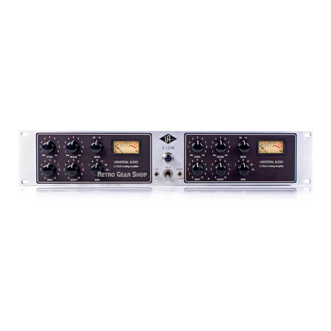
Universal Audio 2-1176 User manual

Universal Audio

Universal Audio 2-1176 User manual

Universal Audio 2-LA-2 User manual

Universal Audio

Universal Audio 2-LA-2 User manual

Universal Audio DCS User manual

Universal Audio

Universal Audio DCS User manual

Universal Audio 6176 User manual

Universal Audio

Universal Audio 6176 User manual

Universal Audio LA-610 MkII User manual

Universal Audio

Universal Audio LA-610 MkII User manual

Universal Audio 4-710d User manual

Universal Audio

Universal Audio 4-710d User manual

Universal Audio SOLO/610 User manual

Universal Audio

Universal Audio SOLO/610 User manual

Universal Audio M610 User manual

Universal Audio

Universal Audio M610 User manual

Universal Audio 175 B User manual

Universal Audio

Universal Audio 175 B User manual

Universal Audio 1108 Quick start guide

Universal Audio

Universal Audio 1108 Quick start guide

Universal Audio 2-610 User manual

Universal Audio

Universal Audio 2-610 User manual

Universal Audio 6176 User manual

Universal Audio

Universal Audio 6176 User manual

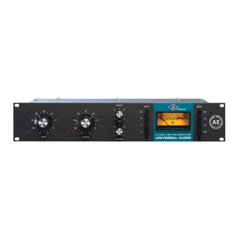
Universal Audio 1176AE User manual

Universal Audio

Universal Audio 1176AE User manual

Universal Audio 2108 User manual

Universal Audio

Universal Audio 2108 User manual

Universal Audio 2-1176 User manual

Universal Audio

Universal Audio 2-1176 User manual

Universal Audio 710 User manual

Universal Audio

Universal Audio 710 User manual

Universal Audio LA-610 MkII User manual

Universal Audio

Universal Audio LA-610 MkII User manual

Universal Audio 1122 User manual

Universal Audio

Universal Audio 1122 User manual

Universal Audio 1176LN User manual

Universal Audio

Universal Audio 1176LN User manual
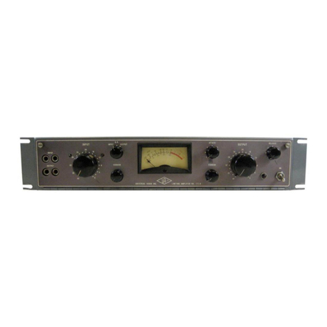
Universal Audio LA-2A User manual

Universal Audio

Universal Audio LA-2A User manual

Universal Audio 1176LN User manual

Universal Audio

Universal Audio 1176LN User manual
Popular Amplifier manuals by other brands

Bose SoundTouch SA-4 owner's guide

Bose

Bose SoundTouch SA-4 owner's guide

Schiit TYR owner's manual

Schiit

Schiit TYR owner's manual

Rotel RB-951 mkII owner's manual

Rotel

Rotel RB-951 mkII owner's manual

Glensound Dante AOIP2M Product details

Glensound

Glensound Dante AOIP2M Product details

Sony XM-460GTX Marketing Specifications operating instructions

Sony

Sony XM-460GTX Marketing Specifications operating instructions

Marantz SC-7S2 Specification sheet

Marantz

Marantz SC-7S2 Specification sheet

Fender Vibro King Schematic diagram

Fender

Fender Vibro King Schematic diagram

Blaupunkt GTA 2100 operating instructions

Blaupunkt

Blaupunkt GTA 2100 operating instructions

HAMTRONICS LPA 3-15R Installation & maintenance

HAMTRONICS

HAMTRONICS LPA 3-15R Installation & maintenance

Gallien-Krueger ML Series Service manual

Gallien-Krueger

Gallien-Krueger ML Series Service manual

FilmoScope EA-MINI-2D-35 installation manual

FilmoScope

FilmoScope EA-MINI-2D-35 installation manual

Omron E3X-DRT21 Operation manual

Omron

Omron E3X-DRT21 Operation manual

Inter-m PP-6214 Service manual

Inter-m

Inter-m PP-6214 Service manual

ORANGE Crush PiX 25BX owner's manual

ORANGE

ORANGE Crush PiX 25BX owner's manual

Santec VVS-3264 user manual

Santec

Santec VVS-3264 user manual

NXP Semiconductors BGA2712 datasheet

NXP Semiconductors

NXP Semiconductors BGA2712 datasheet

Macrom M1A.2250 owner's manual

Macrom

Macrom M1A.2250 owner's manual

Toa 9000M2 Series quick start guide

Toa

Toa 9000M2 Series quick start guide

manuals.online logo
manuals.online logoBrands
  • About & Mission
  • Contact us
  • Privacy Policy
  • Terms and Conditions

Copyright 2025 Manuals.Online. All Rights Reserved.