Dateq SPL5 User manual
SPL-5 MK2_205201_V1.0UK
SPL-5 MKII
Audio Limiter
&
Sound level logger
Manual

SPL-5 MK2_205201_V1.0UK

Due to the nature of this product and it's desi ned functionalities it is considered to be used and
installed solely by professional and certified installers and is not intended for consumer usa e or
resale. Consumer use is not supported by the manufacturer.
SPL-5 MK2_205201_V1.0UK

SPL-5 MK2_205201_V1.0UK

UK DATEQ SPL5 MK2 Manual Safety instructions 5
Safety instructions
1. All safety instructions, warnin s and operatin instructions must be read first.
2. All warnin s on the equipment must be heeded.
3. The operatin instructions must be followed.
4. Keep the operatin instructions for future reference.
5. The equipment may never be used in the immediate vicinity of water; make sure that water and
damp cannot et into the equipment.
6. The equipment may only be installed or fitted in accordance with the manufacturers
recommendations.
7. The equipment must be installed or fitted such that ood ventilation is not obstructed in any
way.
8. The equipment may never be installed in the immediate vicinity of sources of heat, such as
parts of heatin units, boilers, and other equipment that enerates heat (includin amplifiers).
9. Connect the equipment to a power supply of the correct volta e, usin only the cables
recommended by the manufacturer, as specified in the operatin instructions and/or shown on
the connection side of the equipment.
10.The equipment may only be connected to a le ally approved earthed mains power supply.
11.The power cable or power cord must be positioned such that it cannot be walked on in normal
use, and objects that mi ht dama e the cable or cord cannot be placed on it or a ainst it.
Special attention must be paid to the point at which the cable is attached to the equipment and
where the cable is connected to the power supply.
12.Ensure that forei n objects and liquids cannot et into the equipment.
13.The equipment must be cleaned usin the method recommended by the manufacturer.
14.If the equipment is not bein used for a prolon ed period, the power cable or power cord
should be disconnected from the power supply.
15.In all cases where there is a risk, followin an incident, that the equipment could be unsafe,
such as:
●if the power cable or power cord has been dama ed
●if forei n objects or liquids (includin water) have entered the equipment
●if the equipment has suffered a fall or the casin has been dama ed
if a chan e in the performance of the equipment is noticed
Appropriately qualified technical staff must check it.
16.The user may not carry out any work on the equipment other than that specified in the
operatin instructions.
Product support
For questions about the SPL series limiters, accessories or other products contact Dateq at:
Dateq Audio Technologies B.V.
De Paal 37 Phone: (036) 54 72 222
The Netherlands Internet: www.dateq.nl

ndex
Safety instructions..............................................5
Introduction........................................................7
Installation..........................................................8
Connections...................................................9
Audio inputs............................................12
Audio outputs..........................................12
External attenuator..................................12
Si nalin .................................................13
Operation.........................................................14
Technical specifications...................................16
Inputs...........................................................16
Outputs........................................................16
Common......................................................16
Audio.......................................................16
Limiter.....................................................16
Memory...................................................16
External connections...............................16
Dimensions and wei ht...........................16
Introduction confi uration.................................20
Installation........................................................21
Confi uration...............................................21
Confi uration license........................................22
Unlockin the limiter....................................22
Live..............................................................23
Limiter confi uration....................................24
Mode.......................................................24
Limiter settin s........................................24
Certification date.....................................24
Microphone settin s................................24
Timeslots.....................................................25
Bypass calender..........................................25
Display.........................................................26
Firmware update..........................................27
Settin s........................................................28
Network settin s..........................................28
Device..........................................................28
History..............................................................29
Product support................................................32
UK DATEQ SPL-5 MK2 Manual Introduction 7
ntroduction
The SPL-5 MK2 is a sound level limiter that records the sound pressure levels for at least 180
day's. Other events like power cycle, tamper detections or overload on sound level are also
recorded.
Usin the SPL-5 MK2 confi uration software the unit can be confi ured and sound sample data
can be read. On release of the SPL-5 MK2 the confi uration software is supported by windows 7
and hi her. In normal use the SPL-5 MK2 connected to the software is read only. Users can read
all settin s and decibel lo in . To chan e any settin the installer license in combination with the
installer password is required.
To connect to the SPL-5 MK2 a windows-computer with USB support is needed. When the SPL-5
MK2 is connected to a local area network or an internet connection, the software allows to connect
remotely.
The limiter uses an external measurement microphone to determine the current sound level. When
the sound level exceeds the maximum allowed level the limiter will reduce the output level to
ensure the sound level stays within it's limits.
Usin the time and bypass calendar the SPL-5 MK2 can adjust the maximum allowed sound level
automatically durin the day, week and year.
When connected, the special SRL-1 sta e relay an external warnin li ht can be connected and if
needed the power of for example a DJ booth monitor can be cut. This way the sound level is
secured without any compromises to the quality of sound.

8Installation DATEQ SPL-5 MK2 manual UK
nstallation
The limiter is installed in between the audio source (a mixin desk for example) and the speaker
amplifier.
When calibratin the system, the power amplifier has to be set to maximum output level. The
limiter will reduce the si nal as much as needed. When used at nominal level the established
sound pressure limit will not be exceeded after confi urin the limiter. However if in any case this
should happen, e. . When the mixer is used above the nominal level, the limiter will automatically
adjust the si nal to ensure the sound pressure level remains below the maximum allowed level.
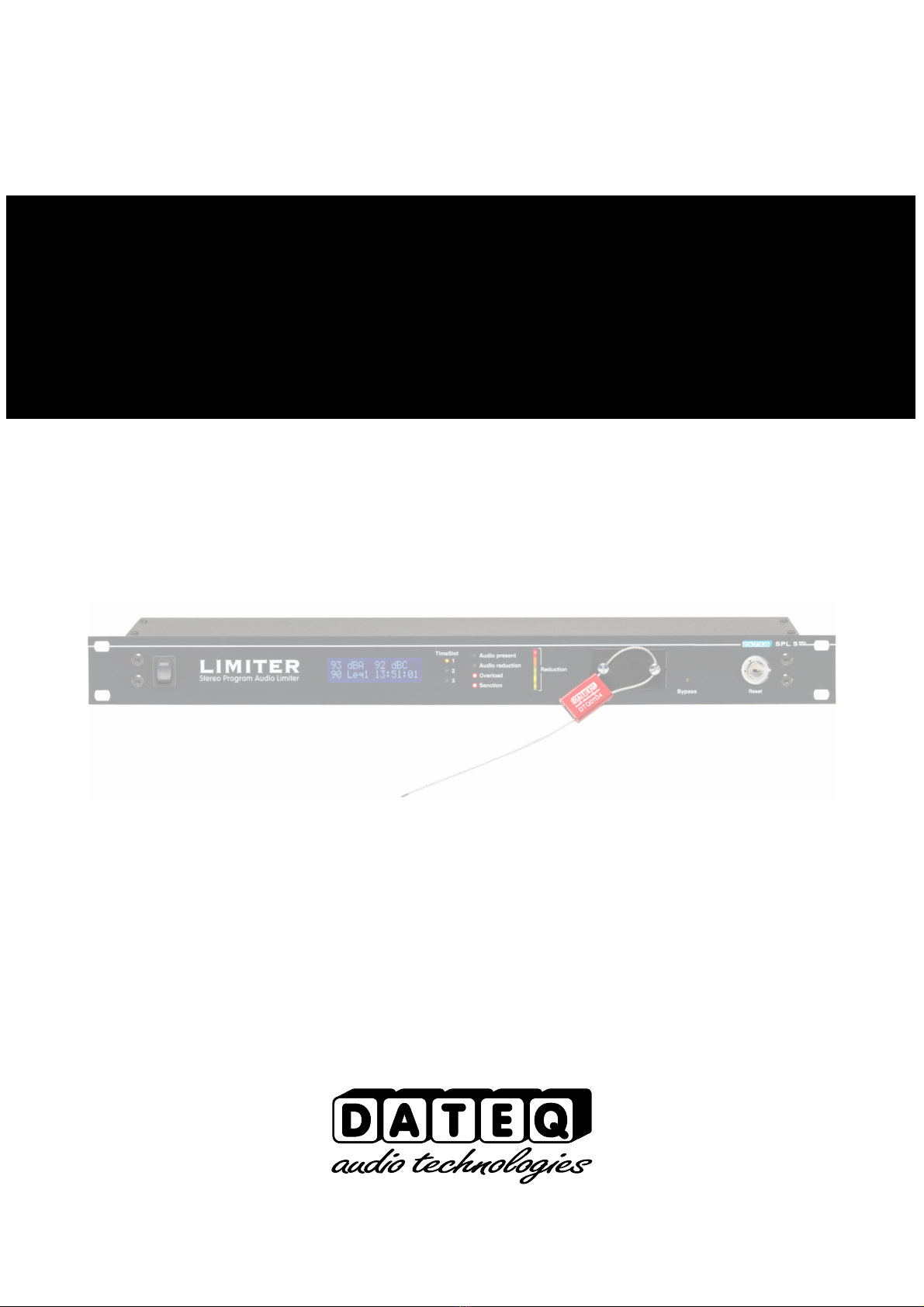
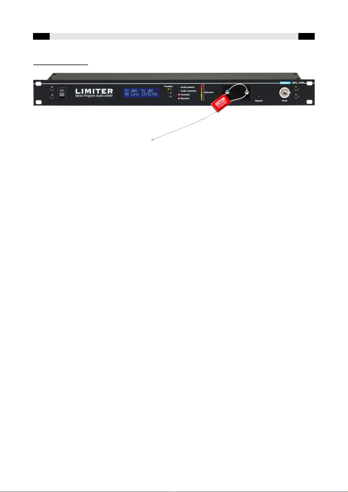
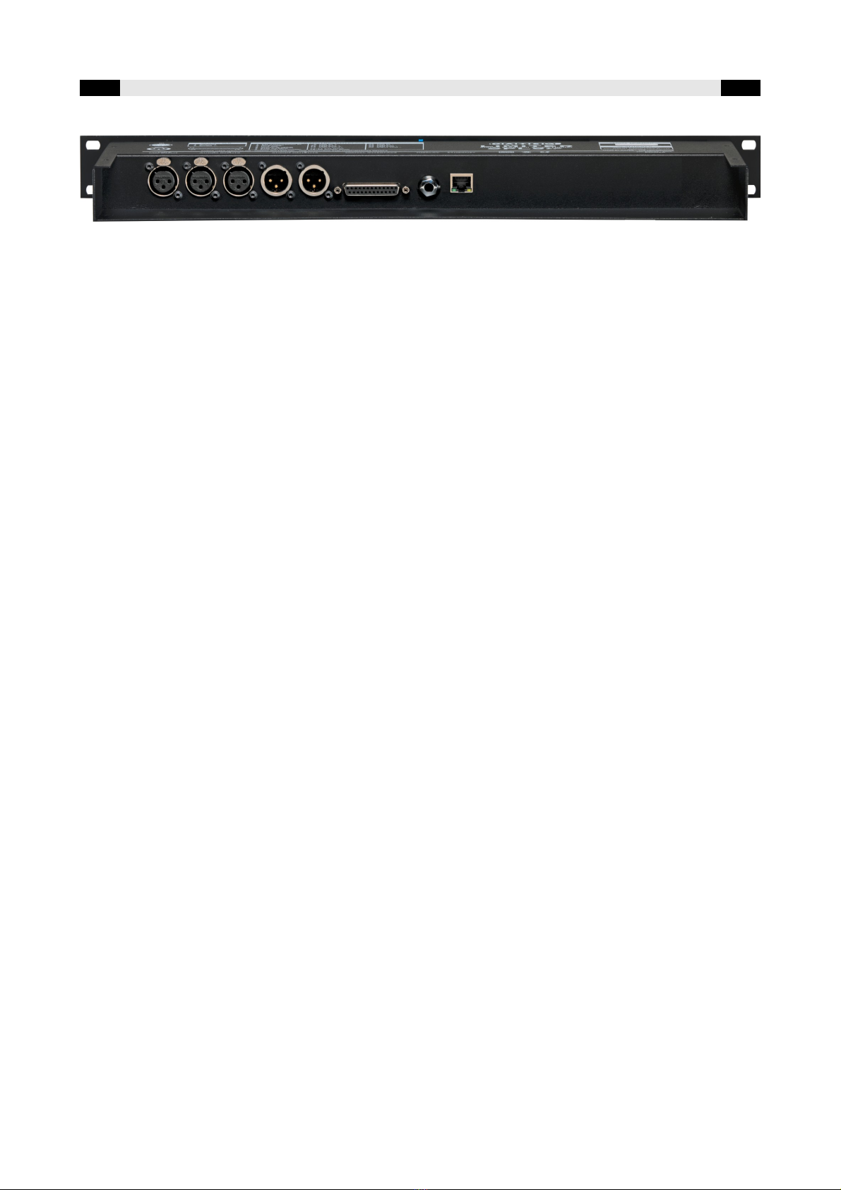
Image 1: Connecting the SPL-5 MK2
UK DATEQ SPL-5 MK2 manual Installation 9
Connections
To prevent modification of the connections after calibration and sealin , the connectors of the
limiter are inaccessible after sealin of the cover plates at the front. To access the connector
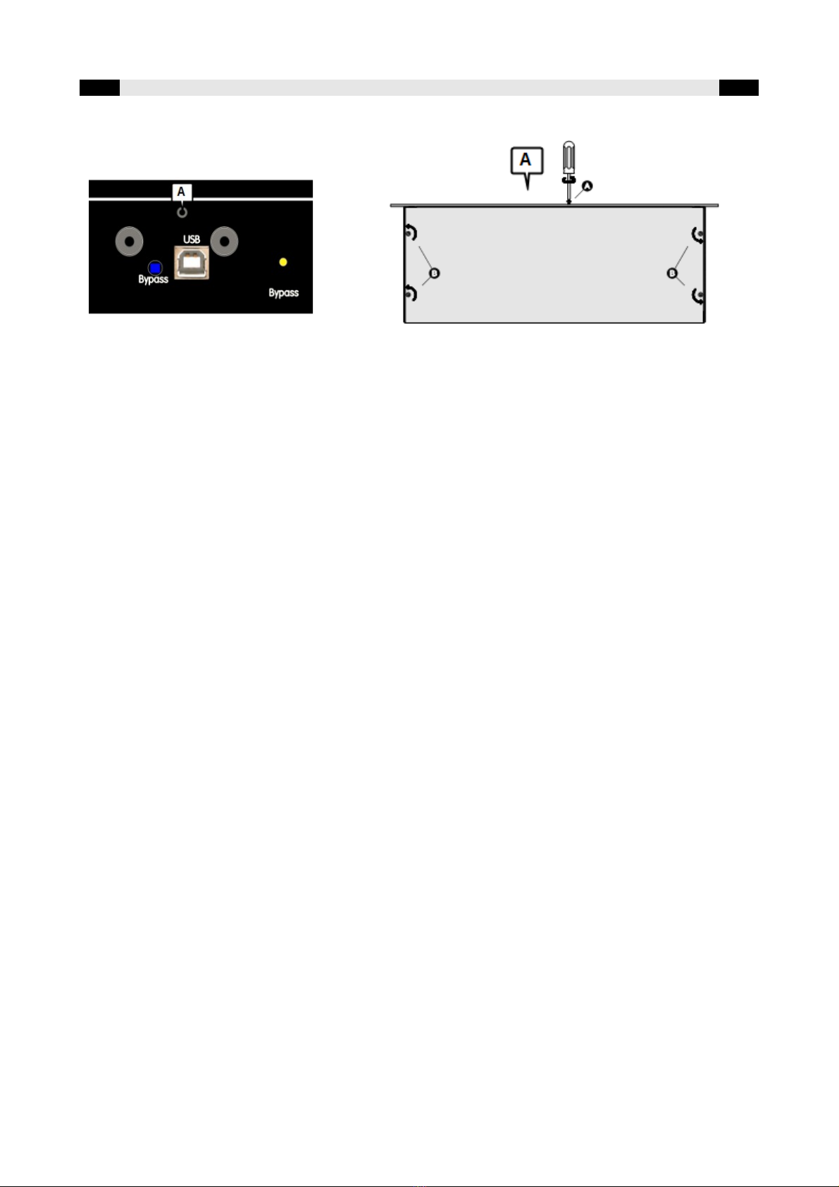
board, remove the ri ht cover plate at the front panel.
Unfasten screw (A) with a torx-screwdriver (see illustration). Now remove the 4 torx-screws (B)
from the top lid. The top cover can be removed now. Gently lift the front side a little, and slowly
shift the top lid to the rear. The connector board will become visible.
The SPL-5 MK2 is equipped with balanced in- and outputs ensurin premium sound quality over
lon er distance. After installin the limiter the cover plate can be replaced, locked and sealed,
ensurin no chan es to the installation can be made. If for some reason the seal is broken, the
cover and the cover is removed, the limiter will store this action into it's memory and optionally lock
the audio path. This sanction can only be reset usin the reset key.

10 Installation DATEQ SPL-5 MK2 manual UK
Microphone input; XLR 3-pin female
Pin Function Description
1 Ground Audio round
2 Audio + Power and audio
3 Audio - Power and audio
Table 1: microphone input connections
Audio inputs left and ri ht; XLR 3-pin female
P1n Function Description
1 Ground Audio round
2 Audio + Audio in phase +
3 Audio - Audio out phase -
Table 2: Audio-input connections
Audio output left and ri ht; XLR 3-pin male
Pin Function Description
1 Ground Audio round
2 Audio + Audio phase +
3 Audio - Audio phase -
Table 3: audio-output connections
USB port; USB-B female
Pin Function Description
1 VCC + Power
2 Data – Data
3 Data + Data
4 GND Ground
Table 4: USB connections
Network port; RJ45 female
Pin Function Description
1 TX-D + Data
2 TX-D – Data
3 RX-D + Data
4 Not connected
5 Not connected
6 RX-D – Data
7 Not connected
8 Not connected
Table 5: Network connections
UK DATEQ SPL-5 MK2 manual Installation 11
Si nalin connector; DB-25 female
Pin Function n/ output
1 External attenuation In
2 Reduction si nalin Out; 15V/ 5mA max.
3 Overload si nalin Out; 15V/ 5mA max.
4 Live OK si nalin Out; 15V/ 5mA max.
5 Warnin si nalin Out; 15V/ 5mA max.
6 Level OK si nalin Out; 15V/ 5mA max.
7 Safe sound level si nalin Out; 15V/ 5mA max.
8 External display In/ out
9 Microphone + In
10 Left audio in + In
11 Ri ht audio in + In
12 Left audio out + Out
13 Ri ht audio out + out
14...17 Di ital round (only for si nalin
connections)
18...20 Analo ue round (only for audio
connections)
21 Microphone - In
22 Left audio in - In
23 Ri ht audio in - In
24 Left audio out - Out
25 Ri ht audio out - Out
Table 6: DB25 connections
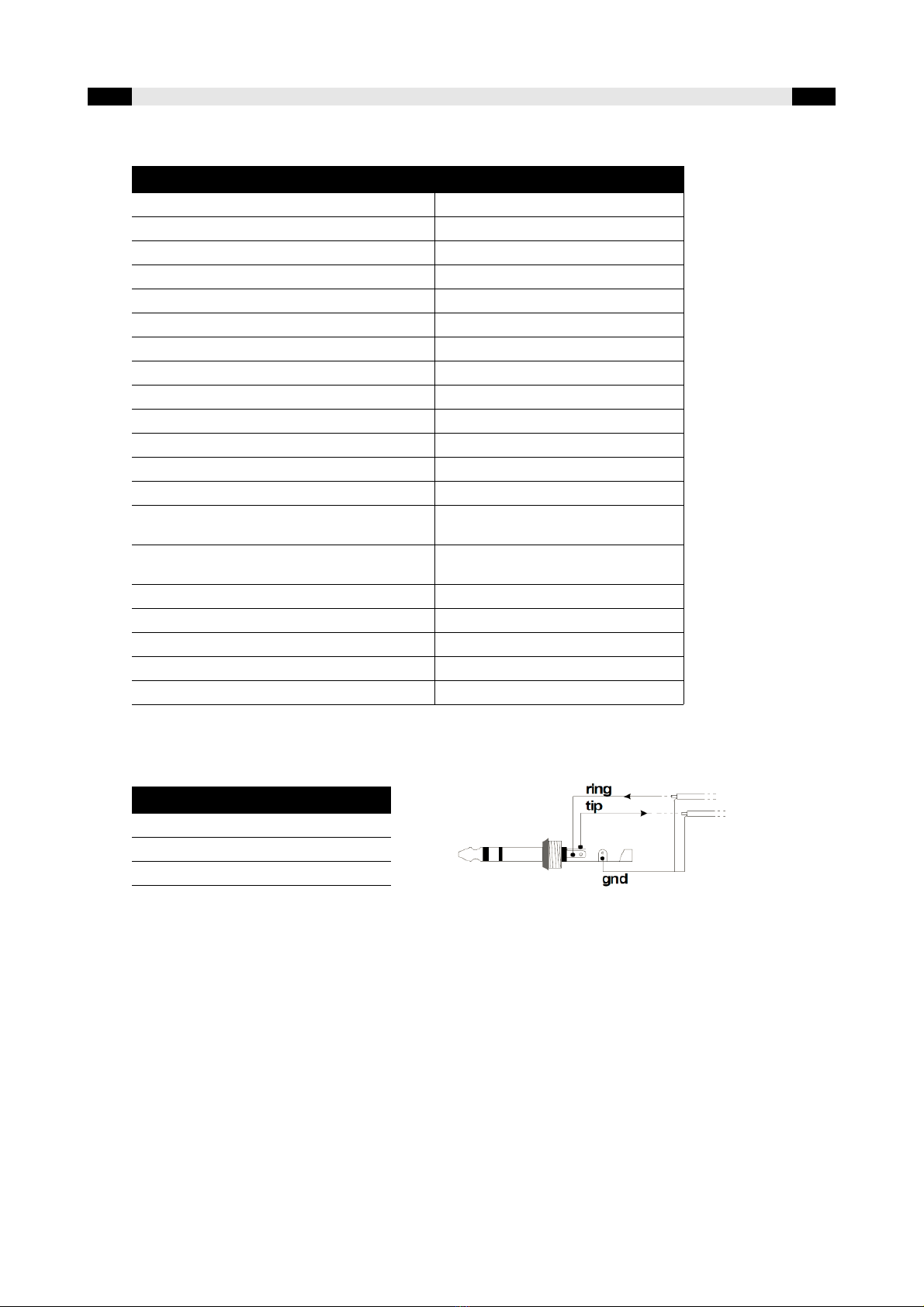
External display; Jack 3-pens female
Pin Function Description
SL Ground Data round
Tip Data TX Data transmit
Rin Data RX Data receive
Table 7: Extern display connections
Microphone input
Connect the supplied measurin microphone here. The wirin of the microphone can be
len thened with standard microphone cable. Pay attention to the polarity of the wirin . If
the microphone is wron ly connected it won't work. The limiter will ive an error messa e,
and the volume will be extremely reduced.
The microphone should be installed so that it 'hears' both sound from the speakers as well
as the sound from the crowd in the room. The microphone can be placed closer to the
speakers when the maximum allowed level is very low. This reduces the effects of
back round noises.

12 Installation DATEQ SPL-5 MK2 manual UK
Audio inputs
Balanced audio inputs. Pin 1 and 3 of the XLR connector should be linked to ether when
the mixer only has unbalanced outputs. The mixers' si nal can be connected to pin 2, and
the round to pin 1.
Audio outputs
Connect the power amplifiers here. Connect pin 2 (si nal) and pin 1 ( round) when the
power amplifier does not have balanced inputs.
External attenuator
This input can be used to reduce the maximum sound pressure level with an external
potentiometer. The maximum sound pressure level can be reduced by connectin a linear
10kOhm potentiometer between pin1 and pin 14.
This can be useful to reduce the sound pressure level from behind the bar. It is also
possible to automatically reduce the sound pressure level, for instance when in the summer
some doors are opened.

UK DATEQ SPL-5 MK2 manual Installation 13
Signaling
Reduction signaling
An indicator to show that the limiter has reduced the si nal level can be connected to this output.
This output has the same function as the reduction LED on the front of the limiter (Audio
reduction).
O erload signaling
This output indicates an overload somewhere in the limiter. This can be the measurin microphone
or the audio input. This output has the same function as the overload LED on the front.
Li e OK signaling
This output is active as lon as the limiter is not in sanction mode. A solid-state relay, to turn off
the power supply of the live band, can be connected to this output. If the maximum sound
pressure level is exceeded by a band, the limiter will o into sanction mode and cut off the power
supply automatically. After a pre-set duration the sanction will be dissolved.
Warning signaling
Le el OK
Safe sound pressure
These outputs ive an impression of the actual sound pressure level with respect to the maximum
allowed level:
•The warnin si nalin output becomes active, as soon as the maximum sound pressure level is
exceeded.
•Level OK indicates that the sound pressure level is below the maximum allowed level, but is
ettin close (0...12dB span).
•Safe sound pressure indicates that the sound pressure level is well below the maximum allowed
limit (12dB or more).
These indicators can be placed near the disc-jockey, or the live band, to ive them an impression
of the sound pressure level.
External VU unit
This is the data connection with the optional SPL-D2 MK , SPL-D3 or SPL-EXT3 display. The
external display can also directly be connected to the SPL-5. For this a stereo 6.3mm jack cable is
required.

14 Operation DATEQ SPL-5 MK2 Manual UK
Operation
1 2 3 4 5 6 7 8 9
1. Power switch:
switches main AC power on or off for the limiter.
2. Display:
The display shows all important values like system time, current sound level in different values
(dBA, dBC, Leq and line level) and the current reduction.
3. Timeslots:
these LED's indicate the current active timeslot. Each timeslot can be confi ured with it's own
time and maximum sound pressure level.
4. Status LED's:
•AUDIO PRESENT indicates active audio detected on the audio inputs of the limiter (detects
at -24dB),
•REDUCE LED indicates the limiter is actively reducin the audio si nal,
•OVERLOAD LED indicates an overloaded si nal present at the line or microphone input
(12dB above threshold level),
•SANCTION LED indicates the limiter in sanction state. On fraud detection the limiter will also
o into sanction state. The sanction LED will blink. Reset by timer or reset key.
1. Reduction LED's:
The reducion is indicated in the percenta e of the maximum allowed limiter reduction. Default
this is set to 30dB that results in 6dB/LED.
•All off: no reduction
•1 LED on: 1-20% reduction
•2 LED's on: 20-40% reduction
•3 LED's on: 40-60% reduction
•4 LED's on: 60-80% reduction
5 LED's on: 80-100% reduction
2. Bypass switch:
This switch puts the limiter fully in bypass. The limiter will no lon er act as limiter, but will only
record measured sound levels.
3. USB:
USB connection for readin historic sound levels and chan in the limiter settin s.
4. Bypass LED:
Indicates the limiter is in bypass mode. The bypass switch or bypass callander is active.
5. Key switch:
After removin the cover lid, the key needs to be set to the blue position to reactivate the
limiter. After reactivatin the key needs to be returned to the red position. The key switch also
resets sanction.
UK DATEQ SPL-5 MK2 Manual Operation 15
10 11 12 13 14 15
10.Microphone:
3-pins XLR-connection for the standard DCM-5 microphone.
11.Audio input:
3-pins XLR-connection for left and ri ht audio input.
12.Audio output:
3-pins XLR-connection for left and ri ht audio output.
13.Si nalin connector:
Sub-D 25 connector for connection external si nalin , audio in- and outputs and the
measurement microphone.
14.Link:
Link connection for an external display SPL-D2 MK2, SPL-D3 of SPL-EXT3.
15.Ethernet:
Ethernet connection for IP-link over a local network to the confi uration software.

Technical specifications
nputs
Mic (Measurement microphone)..............................XLR-3 female. Use only the ori inal DCM-5 microphone.
Line (left and ri ht)...................................................XLR-3 female. Electronically balanced
Input sensitivity..............................................+18dBu maximum
Input resistance.............................................50kOhm
Commom-mode reduction.............................>86dB
Outputs
Line (left and ri ht)...................................................XLR-3 male. Electronically balanced.
Output resistance..........................................50Ohm
Common
Audio
Frequency response......................................20Hz...22kHz @ -1dB
Si nal/ noise ratio..........................................>100dB
THD+N (IEC-A)..............................................<0.02%
Limiter
Threshold................................................50...120dBA (resolution 1dB)
Output correction....................................-50...0dB (resolution 1dB)
Microphone correction............................-30...+12dB (resolution 1dB)
Maximum attenuation adjustment...........-6...-50dB (resolutie 0,5dB)
Memory
180 days
*Soundle el data and e ent logging are stored for maximal 180 days or less when memory is full. The memory system will delete and o erride oldest data first.
Norm
EU: Measurement chain desi ned to comply accordin specifications
IEC-61672-1 class 2
France: Measurement chain desi ned to comply accordin specifications
NFS 31-122-1-2017 and decrét 2017-1244
BE: Measurement chain desi ned to comply accordin specifications
VLAREM-II Cat.1, Cat.2 and Cat.3
DE: Measurement chain desi ned to comply accordin specifications
DIN-61672, DIN-60651 and DIN15905-5
External connections
External attenuation................................0...-20dB (10kOhm lin. potentiometer)
Si nalin and switchin outputs.....................15V/ 5mA max.
Supply volta e........................................100...240VAC/ 50Hz
Power usa e..................................................15W
Dimensions and weight
Front.......................................................483mm x 45mm (B x H) = 19inch/ 1HE
Depth......................................................175mm
Wei ht....................................................3,2k
SPL-5MK2_204901_V1.0EN

SPL-5 MKII
Audio Limiter
&
Sound level logger
Configuration

Notes

ndex
Safety instructions..................................................5
Introduction.............................................................7
Installation...............................................................8
Connections.......................................................9
Audio inputs.................................................12
Audio outputs...............................................12
External attenuator......................................12
Si nalin ......................................................13
Operation..............................................................14
Technical specifications........................................16
Inputs...............................................................16
Outputs............................................................16
Common...........................................................16
Audio...........................................................16
Limiter..........................................................16
Memory........................................................16
External connections...................................16
Dimensions and wei ht................................16
Introduction confi uration.....................................20
Installation.............................................................21
Confi uration....................................................21
Confi uration license............................................22
Unlockin the limiter.........................................22
Live..................................................................23
Limiter confi uration.........................................24
Mode............................................................24
Limiter settin s............................................24
Certification date..........................................24
Microphone settin s.....................................24
Timeslots..........................................................25
Bypass calender...............................................25
Display.............................................................26
Firmware update..............................................27
Settin s............................................................28
Network settin s...............................................28
Device..............................................................28
History..................................................................29
Product support....................................................32

20 Confi uratie DATEQ SPL-5 MK2 Handleidin UK
ntroduction configuration
The SPL-5 MK2 is a sound level limiter that records the sound pressure levels for at least 180
day's. Other events like power cycle, tamper detections or overload on sound level are also
recorded.
Usin the SPL-5 MK2 confi uration software the unit can be confi ured and sound sample data
can be read. On release of the SPL-5 MK2 the confi uration software is supported by windows 7
and hi her. In normal use the SPL-5 MK2 connected to the software is read only. Users can read
all settin s and decibel lo in . To chan e any settin the installer license in combination with the
installer password is required.
To connect to the SPL-5 MK2 a windows-computer with USB support is needed. When the SPL-5
MK2 is connected to a local area network or an internet connection, the software allows to connect
remotely.
The limiter uses an external measurement microphone to determine the current sound level. When
the sound level exceeds the maximum allowed level the limiter will reduce the output level to
ensure the sound level stays within it's limits.
Usin the time and bypass calendar the SPL-5 MK2 can adjust the maximum allowed sound level
automatically durin the day, week and year.
When connected, the special SRL-1 sta e relay an external warnin li ht can be connected and if
needed the power of for example a DJ booth monitor can be cut. This way the sound level is
secured without any compromises to the quality of sound.
Other manuals for SPL5
2
Table of contents
Other Dateq Music Equipment manuals


Popular Music Equipment manuals by other brands

Solid State Logic
Solid State Logic XLogic Super Analogue owner's manual

Oakley
Oakley Equinoxe user manual

Dynacord
Dynacord CLS 222 - operating manual

Pro-Ject Audio Systems
Pro-Ject Audio Systems Pro-Ject Power Box RS Phono Instructions for use

Mosaic
Mosaic ADSR ENVELOPE manual

Rolls
Rolls RDB104 owner's manual


