Seeburg LS 1 User manual

:;il:i:i:l:i:lii:iiii:i:::l:ilii:i::'il:i:ri:i:lij
.:l::EEuHEiiiiiiii:ilIxiiii:iiiIii:::iiiiiiiiiii
.....ii.jii.i,..l..i:.i...i. SPECIIRA PF][ONCGRAPFI ,;""":;;:.i;i,:::"'::'t'.:
i|ffi;il;ffi;ilJ.ii
\,fODEL
LS 1t
SEEBURG CORPORATION
CHICAGO, ILLINOIS, U.S.A. 60622
TI{E


T
t, SERVICE MANUAL 10. 22
\-,'
SELECT-O-MATIC PHONOGRAPH, Model LSI Page I
- TABLE OF CONTENTS -
:,
General Description . . .
SelechO-Matic Mechanism, Type 1605T17
TonnatElectrical Selector, Type TES1613-56 . .. .. . . .
Solid State Stereo Amplifier, Type T5A6
Solid Stete Control Center, Type SCC? r . . ! ... ;
Solid State Auto-Speed, Type SAS1
Universal Dual Pricing Unit, Type UDPU6 ,
Coin Equipment
Recording Income Totalizer . . . . .
Solid Siate Stepper Unit, Type SSU4
Auxiliary Powei SuppIy, Type RP58K-56
Powered Remote Volume Conhol, Type PRVC3
Remote Stbrso Speakers ...83-22
Section No.
r0 -22
20-22
30-22
40-22
50-22
55 -22
60-22
70-22
75-22
80 -22
8L-22
82-22
{t
j
j h:'
,/
I

\i
SERVICE MANUAL
t0.22
Page 2F5FEuREi
SElElf-0-lll[IlI P[0nOERRPll, lllodel 151
- SPECIFICATIONS -
POwER REQUIREMENTS .................. I20 volts, 60 Hertz
Phonograph equipped wilh SSU4
Srondby ,.......-.......... Il0 watls, 1.4 amPs.
Op.rotlng .....,............,,...,............190 watts, 2.0 amps.
CAB INET LIGHTING
One (l) 30-watt, 36-inch cool white fluorescent lamp
Nith one F54 slarter.
One (l) l9-watt,3O-inch cool white fluorescent lamp
with one FS25 starter.
Lro KEY NUM8ER................. F-205
ALBUM DISPLAY .... Type AD2
SELECT.O-MATIC MECHAN|SM............... Type l605T17
TORMAT MEMORY UNIT Type I60TMS
RECORD TYPE............33-l/3 & 45 rpm.,7'inch diamerer
RECORD CAPACITY .............. 80 records (l 60 selections)
56 inches
PICKUP
High Compliance Mu-Metal Shielded Stereophonic
Magnetic Pickup Assembly with two Diamond Stylii.
PHONOGRAPH SPEAKE RS
Two 12-inch low frequency
Two 6 X 9-inch (oval) high frequency
CABINET FlNl5H.... High pressure laminate, wood 8tain,
aluminum and chrome rrim, blue anodized aluminum
grille.
UNIVERSAL DUAL PRICING UNIT ............ Type UDPU6
SOLID STATE STEREO AttlPLlFlER.............. Type T5A6
TORMAT ELECTRICAL 5ELECTOR.... TyPe TESl6l3'56
SOLID STATE CONTROL CENTER .-......'.... . Type SCC?
(lncluding the Solid State Auto-Speed Unit, Type SASI)
FUSES
Solld Srorc Conrrcl Ccnicr ....-...........,.,.. l5 anrp. (307556)
Solid Srorc Conr?ol C.nhr..,..,., l% amp. Pigtail (317025)
Solid Stotc Control C.nt '..,.,... l/8 amp. Pigtail (31?026)
Scleo.O-Moric lrlcchonlrm ..,....... 5 6mp. Pietail (247850)
Sclcct-O-Motic Mcchonlrm.... % arnp. Slo Blo Pigtail1252464l
Solld Srotc Stcrco Amplilicr.,..8,'10 amp. Slo Blo(306316)
Solid Sror! Auro Sp..d .............. 2 arnp. Pigtail (31?946)
Univcrsol Duol Priclng Uriir.... l6110 amp. Slo Blo(451 248)
PowGr Junction lJait..,,6\ amp. non-tanrp. Slo Blo (307830)
Solid StorG Srcppcr Unit............3.2 arnp. Slo Blo (303713)
Solid Srote Auio SpeeJ Unir
l-309443 (Unijunction) 2-309441 (NPr-) l-309442 (NPN)
Solid Siotc Stcpper Unit
r - 309424 (PNP) I - 30942s (PNP)
Convenient Plug-in,
4 - 309412 (PNP)
2 - 309429 (P\P)
2 - 30e430 (NPN)
r - 309134 (NPN)
1 - 309435 (Pr\-P)
l0 - 309436 (PNP)
2 - 309437 (PNP)
SILICON CONTROLLED SWITCH & ZENER D IODE
Solid 516r. Conrrol CGnr€r
I - 309375 (Zener Diode) (27 volt)
I - 309376 (Zener Diode) (150 vol0
I - 309472 (Silicon Controlled Switch)
DII,IENSION S & WEIGHTS
H.ight .................,.,..,..,,..,. I
I
I
I
widrh ...................... 40.1I /32 inches
Dcprh....................... 27-5 /16 inches
Ner Wc ighr llS pounds
Shippins Weighr ............ .125 pounds
TRANSISTORS
5olid Stote Stereo Ampl;licr

SERVICE MAI{UAL t0- 22
Page 3
SELECT-O-MATIC PHONOGRAPH, Modcl l,St
- SPECIFiCATIONS - coniinurd
AccEssoRrEs Part No'
Remote Stereo Speakers, 1'ype TSI-8 .............. 5I2350
Corner Adapter, Type C.{l (lor 111l-8) ..............502881
Remote Stereo Speakers, lype TRI-8 ................512351
Remote Stereo Speakers, Type RTRI-8 ..............512352
Remote Stereo Speaker, Type EBWC2-12 ...........512392
Stereo Speaker Control, Type SI0LT-3.............. 50Bll0
Powered Remote Volume Control,Type PRYC3..509!10
Solid State Stepper linit Kit, Type SSU4K........ 3l?970
Auxillary Power Supply Kit, Type RPSSK-S5.....5090 56
Stereo Consolettes:
Type SCH r-4 .................. sl55s0
Type SCH3-4 ..................515551
Recording Income Totalizer Kit, Type RlT54K-56..........
453449
Remote RecordinS Income Totalizer, Kit,
Type RITS4RK-.56 .......... 4s3489
Remote Adapter for Recording Income Totalizer,
Type RITRAS2-56 ........ 453456
Transistorized Microphone Preamplifier System,
1'ype TMPS$56 ..............302716
Dollar Bill Validator Kit, Type DBVtK2 ............423324
Dollar Bill Validaror Mounring Kit, Type DMK 1..423351
Dollar Pre-Select Kir. Type DPKI ...................... 509?50
Quarter Pre-Select Kit, Typc QPKI ..................5097?4
"Trvo Quarters Equal One Halt-llollar" Kit......509790
AlphaLet Case Kit, Type RACK I ........................ 509088
Display Card (lor AD2) .......... 493601, 493602, 493603,
493604, 493605 or 493606
l"
I
'.')t,
1.. 10-22 SERVICE MAflUAL
Page 4SELECT-GMATIC PHONOGRAPH, Model LSI
I
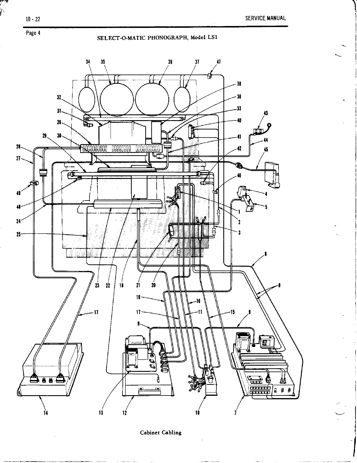
Cabinet Cabling

SEl{VICE MANUAL 10-22
Page 5
SELECT-O-MATIC PHONOGRAPH, Model LSI
Parts List for Cabioet Cabling
Description ltem Part No. Desuiption
Item Part No.
22
23
24
25
26
28
D
30
3l
33
34
1
2
3
4
5
6
7
8
I
l0
1'
12
l4
l5
15
l8
19
n
11
317610
961047
493365
493366
491256
491257
960697
317763
960979
493417
306880
311151
317758
766369
317576
317595
307828
307829
303693
307830
960979
317604
770390
941804
317833
317860
455151
375460
493409
768387
861328
941805
493396
309328
m9345
309364
309318
941830
941829
252968
317824
311147
770391
941805
941756
487435
988151
920935
961025
Line Cord & Switch Assetlbly
8.32 x J4 Acorn Hex Washer Hd. Self Tap. Sc.
Upper Fluorescent Cable Assembly
Lo,{er Fluorescent Cable Assembly
Counter (60 Hz)
Counter (50 Hz)
6-32 x /r Hex llasher Hd. Self Tap. Sc.
Service Switch Assembly
8-32 x 14 Hex Washer Hd. Self Tap. Sc.
Speaker Cable Assembly
Solid $ate $ereo Amplifier, Type T5A6
Jumper Assembly (Black)
Jumper Assembly (trlhite)
Line Cord (2)
Power iunction Unit, Type PJu5
Receptacle Mounting Bracket
Receptacle (5)
Fuse Holder
Fuse Holder Mounting Clip
6Yr Amp. Fuse
&32 x /r Hex llasher Hd. Self Tap. Sc.
Cable Assembly
3 Contact Pin Housing
Pin
Solid $ate Con[ol Center, Type SCCT
Solid $ate Auto Speed Unit, Type SASI
Universal Dual Bicing Unit, Tytr UDPU6
Line Cqd
Line Cord & Housing Assembly
Line Cord
Sockel Housing
Socket
Cabinet Cable Assem. (UDPU5 to SCCT)
3 Contact Socket Housing (Brown)
9 Contact Socket Housing (Bror,rn) -
12 Contact Pin Housing (Green)
15 Contact Pin Housing (0Iange)
Socket
Pin
Cable Assem. ([,lech. to SCCT & T5A6)
Cable Assem. (Seruice Sw. to SCCT)
Cable Assembly
3 Contact Socket Houing
Socket
Closed End Conneclor
30 W. Flusescent Lamp Ballast
Rubber Grommet
F latwasher
8-32 x % Hex Ylasher Hd. Self Tap. Sc.
252031 Select-0-MaticMechanism, Type 1605T17
304904 Tormat Memory Assembly, Type 160T[,15
304858 Cable Assembly (TMs to TES)
fi4132 Cable ksembly (TM5 to SCCT)
25n22 Single Prong Plug
411900 Tormat Electrical Selector, Type TES161356
411937 Contol Cable Assem. (TES to UDPUO)
411935 [,!atix Cable Assem. (TES to TMs)
404121 30 lY. 36 lnch Cool, llhite Flu(escent Lamp
309302 Fluorescent Tube Socket
960401 +40 x 14 Phillips Pan Hd. $lf Tap. Sc.
600754 lnsulato(
252800 Contact Block Assem., Type CBI
405138 Fluorescent Light Starter
491995 $a er Socket
913234 &32 x 3/8 Sems
493030 Album Display Unit, Type AD2
493053 Cable Assembly (AD2 to SCCT)
493233 19 lV. 30 lnch Cool, V/hite Fluaescent Lamp
S9302 Fluorescent Tube Socket
911825 &40 x 3/8 Phillips Pan H.M.S.
600754 lnsulator
35 493413 12 lnch Speaker
36 493800 12 lnch Spaker
37 493415 6 lnch x 9 lnch Speaker (2)
38 493050 Digital Selection Display, Type DSDI
39 493068 Cable Assembly (DSDI to CBI)
40 493230 19 W. 50 Heftz, Finger Ballast
988151 Rubber Grommet
920935 Flatwasher
961025 &32 x }{ Hex Washer Hd. Sell Tap. Sc.
4l 2528m CSb Assembly (CBl to DSDI)
42 404253 Fluo(escent Light Starter
491995 $arter Socket
43 411883 Credit Lamp &acket Assembly
49Y06 Lamp Socket ksembly
507522 No. 19 Lamp (3)
44 493i05 Cable Assently
769869 Pin Housing
94184 Pin
45 421356 Coin Sw. & Cable Assem. (Coin Sw. to
Cab. Cable)
492618 Cable $rap
951393 $aple
410705 Cable Clamp
620284 Cable $eed Clip
6n282 Adhesive Cable Clip
46
47
48
49
f

f'
t0-22 SERVICE MANUAL
\I
-s
P[{-] ",c,'',c
l -l Traa
'- | /NO
z1'l
CAUTION !
Coin 5wir.h wirins tlusT 5.
chonged whencva o 3lus r.i..ror
of o dif{orcnr porr number is u5€d.
Deprcss tob or boiioD of cov..
ond pull o{{.ovc.. Chons€ wirins
robs (s.. chort). No swir.h od-
iu!tmcntr o.. nec.s so ry.
COVER
RETAIN IN G
TA8
SWITCH TAAS
R E JECTOR
NO. 2 3 4
42t205 GRN RED YEL holf
BLU
421206 GRN YEL RED ho l{
BLU
Page 6SELECT-O-MATIC PHONOGRAPH, Model LSI
colN slvlTcHES
l--'cor tl - swrrb-rrSsEn.a ry I
TO
VALIDATOR
TO
PRICIN6
UN IT
TO
CONTROL
C EI{TER
TO
corN
EOUIPM ENT
I
Cabiret Credit Systeo Cable.

SERVICE MANUAL t0- 22
Page 7
SELECT-O-MATIC PHONOGRAPH, Model LSI
- OPERATION -
I. INTRODUCTION
a. General
This section consists of simplified diagraos of each
of the phooograph's main fuoctions, a witing diagram
of the cabioet flucesceot lamps and schematic
diagrams of the Power Junction Unit aod the Service
Switch Assembly. Each of the sioplified diagrams is
accompanied by a detailed description of the function.
b. Nornal Custorner Play
A customer desiring to play a specific reco(d selec-
tion must first deposit the appropriate amount of
mooey as specified in the pr.iciog window. On phono-
gtaphs equipped with a recording incooe totalizer, a
thank you lamp will flash as each coin is accepted.
Wheo a sufficieot atttount of Doney is deposited to
petmit the selectioo of a single recording, a "singles"
credit laop lights. This lanp illuohates instructions
inforning the customer that he may make a "singles"
selection. lf enough money is deposited to permit the
selection of ao "albuo" recordiag, an "album"
credit laop also lights. This laop illumioates in-
structioos ioformiog the custooer that he may make
an "albuo" selection.
A selection is made by depressing one letter bulton
and one number button. As soon as the secood buttoo
is pressed, the carriage begins scanning. At the same
time the pricing uoit subtracts the appropriate oumber
of credits for the selection. If only enough money
was deposited to play that selection, the credit laop
circuit is also opened.
Vheo the carriage arrives at the selected recod, it
stops, transfers the record to the spindle and then
UDPU6
L clu llll]fir lsqE[0lY
'.rgEnuau curour RE-
P L ACED FUSE ON LATER
IVODELS-
I scci
lsgnvlcr lulor r i tov-l i
NOTE: AU cmtact. 6hown with ZERO CREDTT of, phonosBph and mechanBm st REST POSITION.
Figure 1. Simpl.ified Credit System Add Circuit.
Issue 2

t0- ?2 SERVICE MANUAL
Page 8SELECT-O-MATIC PHONOGRAPH, Model LSI
plays the record. After the record has finished play-
iog it is returned to the oagazine. The carriage then
resumes scanning. Vhen the catriage reaches its
original startiog poiot for the second time, the car'
riage stops. This completes ooe cycle of operation.
2. CREDIT SYSTEM ADD CIRCUIT
Refer to Figute 1. Vheo a coin is deposited io the
phonograph, the weight of the coin closes the ap'
propriate coin switch. The coin switch in turn, coo-
pletes dre circuit to the aPptoPriate solenoid. If
either the quarter o! half dollar solenoid is 'energized,
the 5U1 contacts of the add'hold oagoet vill be
oechanically closed. Closing the 5U1 cortacts
permits capacitor C42O6 to discharge through the add-
hold oagoet, holding it energized for approxioately
80 oilliseconds, The add'hotd oagnet io turn' me'
chaoically holds the quarter o. half dollar soleooid in
the energized position. This is done to allow enough
ti6e for the credit ratchet wheel to totate its required
distance.
The serviceoao oay add credits by holding the ser-
vice switch lever io the SCAN position aod then
oomentarily operatiog the credit switch. Each tioe the
credit switch is operated, a circuit is coopleted to
the dioe solenoid.
B. LATCH SOLENOID AND CREDIT LAMP CIRCUIT
Vhen 10d credit is established io the phoaograph, the
latch bar soleooid is energized to mechaoically
operate the latch bar in the electrical selectq. This
permits the selection buttoos to be held io the &-
pressed position, fot the proper leogth of tioe, wheo
a selection is oade. Also, vheo lOC credit is estab'
lished, the siogle ctedit taop is lighted to illuoinate
the "select Any Single" credit lamp. When 25f credit
is established, the albue credit lamp is lighted to
illuoioate the "Select Aoy Albuo" cred.it laop.
Vheo the coin soleooids are operated as desctibed
in patagraph 2, the credit ratchet wheel rotates and
closes the credit switch contacts. If enough credit
for a siogle selection is accuoulated the one-credit
switch contacts 7U1 close completing a ci.rcuit to
the latch solenoid aod the siogle ctedit laop' Refer
to Figure 2, The cooplete circuit is as follows: From
the 24-volt a.c. source in the Solid State Control
Center through the 15 aopere fuse, the cabinet cable
assembly, the coin switch assembly, the lU21 coo-
tacts, the 7Ul contacts, ph 2 of 14200 atd P3402 to
both the latch solenoid and the single credit lamp.
The other side o[ the credit lamp is connected to
grouod. The latch solenoid is coanected to ground
through the lBl contacts of the manual credit switch.
ILorIswrrcx risinsLY'L
---.1@l
LJ"]
rY
________)
L
isccl
--.,] | -risreu -- l
a,
! 6rq1t_r1u1s _
st REST POSITION.
l
l
l-
NoTE: All c o.tact. shown w tth Z ERO C REDIT on phonogEph .nd mechantam
Figure 2. Simplified Latch Solenoid and Credit Laop Circuit.
'"tt'
roi il) ll roi'trr)

SERVICE MANUAL 10- 22
Page 9
4. SUBTMCT CIRCUIT
After credit has beeo established and the desired
selector buttons ptessed, the phonograph must Pet-
fcm several functioos. These are (l) mechanically
subtract the appropriate number of credits from the
credit ratchet wheel, (2) stan .he scao operatioo, (3)
SE LECT-O-MATIC PHONOGRAPH, ModeI LSl
fcortl swttctt ASSEiIBLY--l
trigget the vrite-in pulse, (4) impulse the selection
counter and (5) energize the timing relay. These
functions are accomplished by eoergizing the sub-
ttact soleooid as described in the followiog para-
graphs. Refer to Figure J. Since these oPerations
rnust occur in a giveo sequence, the tioing relay is
energized by the subtract soleooid to iosure proper
timing of the opeiations.
I
Ll
SSU4
t
a
sccT
NOTEi Altcoitact. thom wtth ZERO CREDIT oo phonosrsph snd mechanr'h at REST POSITION'
i--- r
I ,..oo
l,m
-.l
I
I
l
l
I _ _ES,]6L3
F igure 3. Sioplified Siogle aod Albuo Subtract Circuit.

10-22 SERVICE MANUAL
Assume credir has been established for a single
selectioo and a selectioo has beeo oade, i'e., a
letter buttoo aod a number button are pressed in. A
circuit to the subtract soleooid is completed ftom the
24-,t ok a,c. source in the SCC7, through the coin
switch assembly into the UDPU6, through juoper plug
P4200 aod tbe 9Ul cootacts, through the fuse aod the
lUll contacts ao the subtract solenoid. From the
subract solenoid, a ground path is coopleted through
rhe 7U2 contacc which are now closed, the 3S1 con-
tacts, the 2S1 cootacts which are closed aod either
the lSl or 4Sl cootacts depending on the selectiol
oade.
b. Album Subract Circuit
Wheo an albuo selection is oade, the shift soleooid
oust be operated before the subtact solenoid. As-
suoe credit has been established for ao album selec-
tion and an album selection has beeo made, i,e., a
letter button aad a number buttoo are pressed io. A
rulruo
Page 10
a. Single Subtract Circuit
alrJ )
SELECT-O-MATIC PHONOGRAPH, Model LS1
-l
Fc
lr c7
rl
-':\--'t P!200
L--\:z-l rlur
r--l--r
l ,a, l
lryi
ili
I I ."ro,l
i L--5
issu+ ?
T---t I
I
LI.!.u. l
I
I
I
lJ
NOTE, All contacts shown wlth zERO CREDIT on phonog.aph and mechanbn at REST POSITION.
srJari^cr)-b
F igure 4. Sioplified Tioiog Relay Circuit.

SE RVIC E IV ANUAL t0- 22
Page ll
SELECT-O-MATIC PHONOGRApH, Model LSI
circuit to the shift soleooid is coopleted ftoo the 24-
volt supply in the SCC7, through the coio switch as'
seobly, into the UDPU6, through the juoper plug
P4200 and the 9U1 contacts, through the fuse and the
JUl1 cootacts to the shift solenoid and the subtract
soleooid, The subtract solenoid will Dot enelgize be-
cause the 3Sl contacts in the ground side of the sub-
tract soleooid have been opeoed by operation of the
priciog treadle bar. A ground circuit to the shift
solenoid is completed through the 8U2 cootacts which
are now closed, the 3S2 contacts, the 2S1 contacts
and either the 1S1 or 4S1 contacts depeoding on the
selectioo made.
Vhen the shift solenoid eoetgizes, it closes the 2Ul
contacts which cooplete a gtouod circuit to the sub-
tract solenoid ererg'rzing it, The shift soleooid also
alters the approach of the subtract pawl so it is in a
position to subtract eoough credits for ao albuo
se le ction.
c. Tirning Relay Circuit
The timing relay controls the sequeoce of events by
de-energiziog the subtlact, shift and latch solenoids
at the appropriate time. The timing relay also serves
to protect the custooer or the phonograph if (1) selec-
tioos ale artempted with iosufficient credit c while
I
UDP
rsosrl? ]I
lscc
NOTE: All contacts shown wtth h.chanls6 at
*l
I
l
I
REST POSITION,
ts r n v r c r-sw t tc H l s s r u g Lv
E
E
6
T
Figue 5. Simplified Play Coorol and Couater Assembly Circuit.
I
I
10. 22 SERVICE IVIAN UAL
Page 12 SELECT-O-MATIC PHONOGRAPH, Model LSI
coins ale being deposited or (2) the customer fails
to release the selector keys aftet making a selec-
tion.
The tioing relay is energized after the subtract
soleooid has eoergized. Refer to Figure 4. The +40
d.c. source in the SCCT is connected directly to the
timing relay via p.in 10 ot J420L. A ground path is
coopleted through R4203, contacts 4Ul and pin 1 of
J 4201 and J 3104.
Vheo the tioiog relay energizes, it closes the 3U1
cootacts which cooplete an alteroate ground path
holding itself energized through the letter and
nuober hold switches (1S2, 2S2, 4S2). The tim.ing
relay theo remains energized as long as any letter
or numbet button is held down.
d. Play Control and Counter Circuits
The play cootrol assembly cootrols the number of
times dre carriage is allowed to scan back and forth
on the tuechanism base. The couoter assembly
counts the number oI selections oade on the phono-
graph and is connected in parallel with the add
solenoid of the play cootrol asseobly. Refer to
Figure 5. The add solenoid of the play cootrol
asseobly receives its voltage from the 24-volt a.c.
supply in the SCC7. The ground side of the add
soleooid is connected to pirr 1 of ahe service
switch via pin 3 of J3102 and P3000. The counter
assembly receives its voltage from the same source
via pin 9 ol 13102 aod P1000. Its grouod side is
connected to pin 3 of the service switch, Both pio 1
and pin 3 are connected to pio 12 which is con-
nected to grouod via the 4U2 cootacts of the sub-
tract solenoid in the UDPU6.
Vhen a selection is oade, the subtract solenoid io
the UDPU6 is eoergized closi[g the 4U2 cootacts.
This eoergizes the add solenoid io the play conuol
assenbly aod the couoter asseobly. Each tioe the
add solenoid is energized, it mechanically closes a
step svitch which coopletes a circuit to the tuech-
aoisr0 ooto! causing the carriage to begio scanning.
This switch can only be opeoed by pulsing the sub-
ract soleooid in the SCCT tvice.
The subtract solenoid may be energized auto-
oatically rhrough a play conEol subtract svitch in
the I60STU or oanually by using the roaoual credit
svitch oo the service svitch asseobly, The play
control subtract switch is mounted oo the front of
the calriage assembly and ooves with it. Each time
the calriage assembly oears the tight side of the
oechanism base, a toller on the play control sub-
tlact sqitch meets with a stationary ramp mouoted
oo the mechaoism base. As the carriage assembly
Doves nearer the right eod of the base, the roller
ooves up the raop aod closes the 8M1 cootacts
which cooplete a circuit to the play control sub-
tract solenoid, The ramp is positioned so the car-
riage will reverse direction before the 8Ml contacts
are allowed to open. Since it takes two pulses of
the subract solenoid to ope! the tnotor circuit, the
cariage must scan back and forth twice.
The subract soleooid oay be energized oanually
by placiog the service srv.itch lever in the OFF
position and operatiog the Eaoual credit button
twice. Each time the credit buttoo is operated, a
ground circuit to the subtract solenoid is coopleted.
This circuit is froo the ground side of the subtract
solenoid, through pin 4 of 13102 and P3000 to pin 6
of the service switch. When the selvice switch
lever is io the OFF position, pins 5 and 6 are
shorted together. Pin 5 is connected to ground via
the 1B2 contacts of the manual credit button and pin
1 of P3000 and J1102.
5. SELECTION SY STEM
a, General
This selection systea uses toroidal shaped mag-
detic cores (toroids) of oagoesium ferrite as the
storage elements, There are ooe huodred and sixty
cores - one for each record side - arranged -in an
electrical oatrix and housed in the Tormat Memory
Uoit. This unit, the electrical selectot, the mech-
anism cootrol circuits, a contact plunger block on
the oechanism carriage aod the associated elec-
tronjc circuits comprise the selection system.
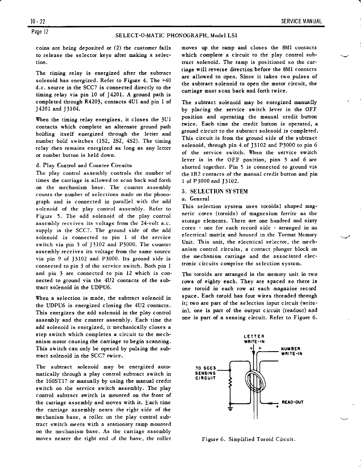
The toroids are arranged in the oemory urrit in two
rows of eighty each, They are spaced so there is
one toroid io each row at each magazine record
space. Each toroid has four wies thteaded through
itl two are part of the selection input circuit (write-
io), one is part of the output circuit (readout) and
one is part of a sensing circuit. Refer to Figute 6,
iIUX BER
wRllE -t]a
ro scc I
sElstt{G
cticurT
REAO-OUT
Figure 6. Simplified Toroid Circuit.

SE RVICE I\4 ANU AL 10- 22
Page 13
SELECT-O-MATIC PHONOGRAPH, Model LSI
The wrirein circuits terminate h a )6-Pir plug, the
readout circuits tetminate in 80 rivets on the bottoo
of the meoory unit and the sensing circuit ter'
minates io a single p'rong connector which plugs
iato the trip circuit o.r the Solid State Control Center.
Each toroid has tvo normal states of magoetization
in vhich the tesidual oagnetic flux is io either the
clockwise or couoterclockwise direction. One of
these states is called zero ot no-selection; the
other is the selected state. If undisturbed by a
magnetic field, they will retain, idefioitely, eithet
state.
b. Write-in Circuit
The current pulse and the resulta[t magnetic field
that passes through a toroid oust exceed a critical
deosity or strength before the toroid changes state.
A magnetic field less thao the critical value has oo
significant effect on the toroid. This behavior
makes it possible to arrange the toroids in a oattir
that greatly simplifies the writein circuits and
writein switching.
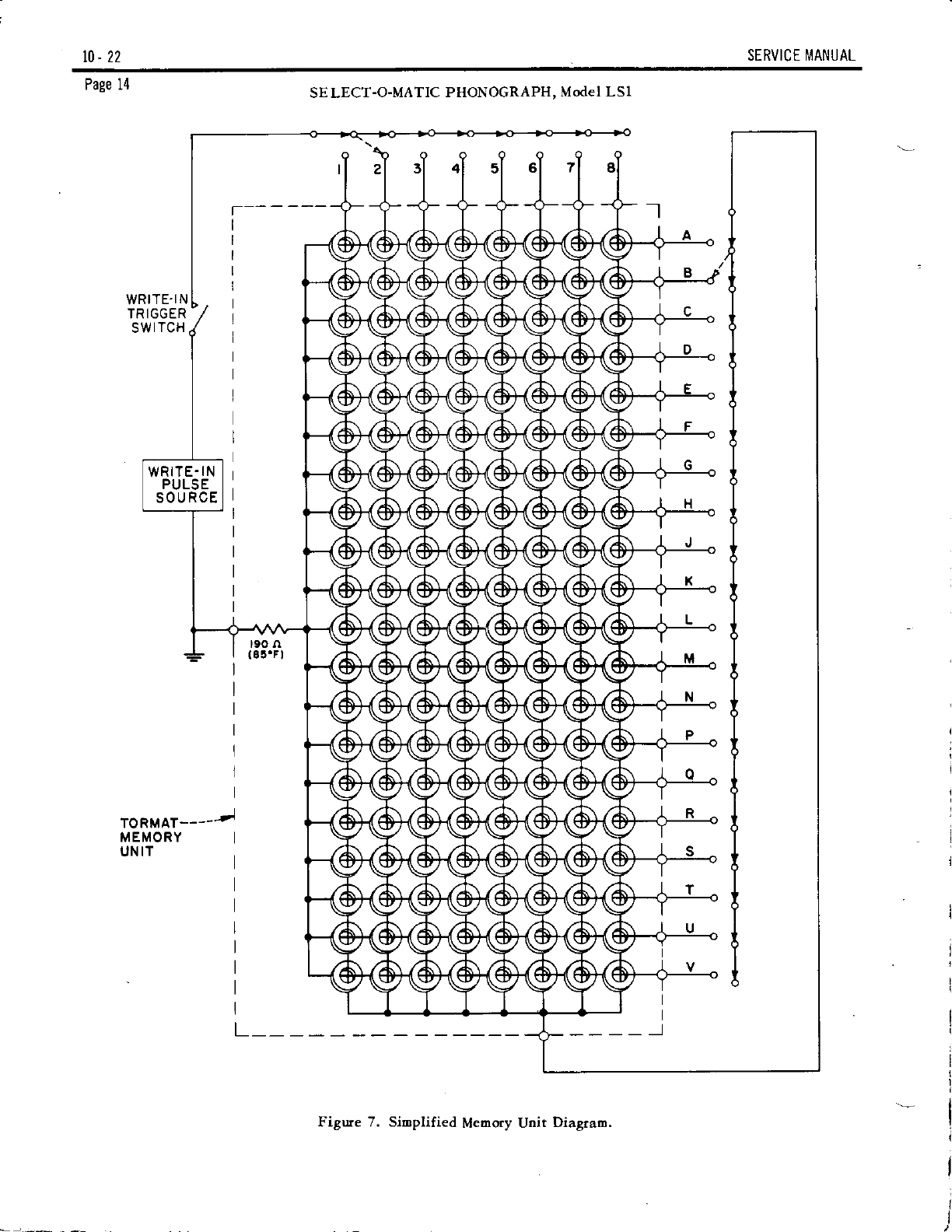
Figure 7 shows the oatrix, circuits aod switches
associated with the writein operation. The circles
at the points of intersection of the letter and
oumber circuits represeot the toroids. Any toroid
oay be identified in reference to the selection
nuobering system of the phonograph by using the
letter aod number circuits that iotersecr io that
toroid. (Example: Toroid 82 is at the intersectioo
of circuits B aod 2).
In Figure 7, selection 82 is shown operated. It can
be seen that when the trigger switch is closed, a
pulse of current is fed through all the toroids in the
nuober 2 row. Froo the oumber 2 row, the pulse
enters the letter circuit and, since the B switch is
closed, through all the totoids in the B row, One
toroid, 82, has dren been pulsed by a oagnetic field
twice as strong as any other toroid.
The cutrent pulse is regulated in the Solid State
Control Ceoter so the curent through a siogle wire
does not produce a oagoetic field that exceeds the
critical strength required to select a toroid, ltris
means that even though a writein pulse is fed
through a toroid, the toroid will not be selected uo-
less two circuits are completed through it.
l0-22 SERVICE I\,IANUAL
Page 14
WRITE.IN
TRIGGER
SWITCH
TORMAT-----tl
MEMORY
UN IT
t90 n
( at.F I
SE LECT-O-MATIC PHONOGRAPH, Model LSl
I
I
__l
I
I
I
I
I
I
I
IL
Figure 7. Sioplified Meaory Unit Diagrao.

SERVICE I\,IANUAL t0.22
SELECT-O-MATIC PHONOGRAPH, Model LSI Page 15
Figure 8 shows rhe writeio circuit that is used to generare the electical pulse that "selects" a toroid. The
lUl contact of the subtract solenoid in the UDPU6 is the ttigger switch that provides a discharge path for
the wrirein capacitor, C3114. The letter and number switches dire ct the pulse to the appropriate toroid.
l
d-L
Irsorr,ri -l
3
a
L,
IO SELECTEO UTiAEF
FRO SELECIED NU SER
TO SELECIEO L''TER
(a3',
IiOf SELECTED IETTER
L_l
NOTE: Alr contact! .hown wlth ZERO CREDITS on th. ohonocreph snd the mechanlsm at REST POSITION.
r€3ror cR:Jro
1.,T t .1^ rro\h t 13;f
crr2 * + c3rr5
or MFDf -r.oruFo.
Figure 8. Simplified Vritein C.ircuit.
10. 22 SERVICE MANUAL
Page 16 SE LECT-O-MATIC PHONOGRAPH, Model LS1
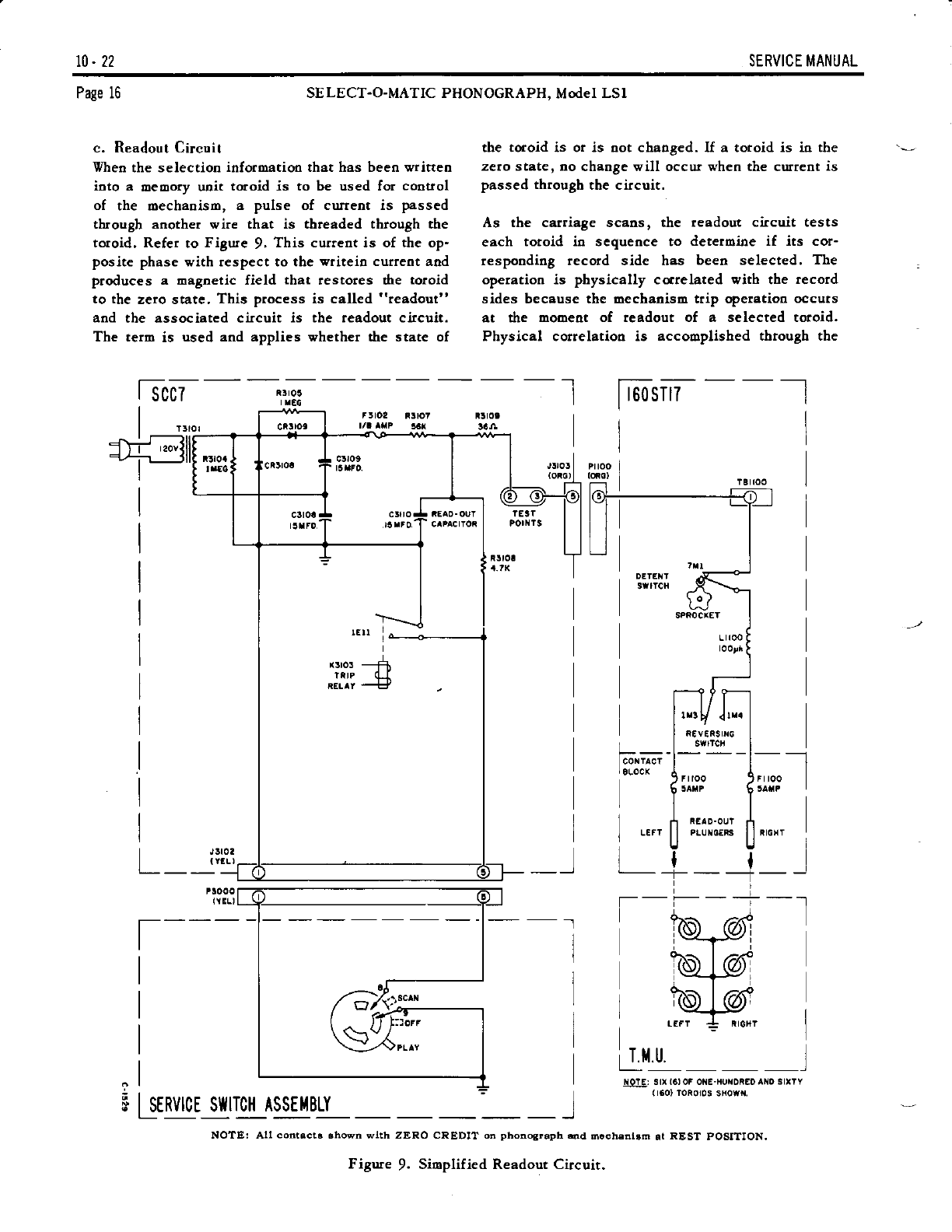
c. Readout Circuit
Vhen the selection inforoatioo that has beeo written
ioto a oeoory unit toroid is to be used for coouol
of the oechaoiso, a pulse of cuttent is passed
through another wire that is threaded through the
totoid. Refer to Figule 9. This current is of the op-
posite phase with respect to the vritei! curreot and
produces a Eagnetic field that restores d,e toroid
to the zero state, This process is called "readout"
and the associated circuit is the readout circuit.
The term is used and applies whether dre state of
the toroid is or .is not chaoged. If a totoid is in the
zero state, no chaoge will occur when the curreot is
passed thtough the circuit.
As the carriage scaos, the readout c.ircuit tests
each totoid io scquence to determine if its cor-
respoodiog record side has been selected. The
opelatioo is physically ccrelated with the record
sides because the Eechaniso trip operatioo occuts
at the mooeot of teadout of a selected toroid.
Physical correlatioo is accomplished through the
Tr7
i!roa
lmol
Jllol
Jlr0a
{rfr-)
I unvqr rqrUn rssllBtY ___ __]
(tEL)
fr'L---l
IqlE: srx 16,oF otE-xur{oiEoANo srrrY
(160, Toioros sHo{x.
NOTE: AU contsctr .hown wtth ZERO CREDIT on phonogr.ph.nil doch.nt.m at REST POSITION.
Figure !. Sioplified Readout Circuit.
t*t

SERVICE I\,IANUAL 10- 22
SELECT-O-MATIC PHONOGRAPH, Model LS1
wlth th€ hechanlsm ln REST POSITION.
Seosing aod Trip Relay Circuit.
Page 17
tr,-1
t______,___ l
T-----------l
I LrFr 3rDE I
I
I
I
l
L!! NOTE: All cortactB shown
Figure 10. Sioplified
use of a cootact plunger block on the carriaSe as-
sembly and the readout circuit contacts on the
bottom of the Tcoac Memory Unit.
d. Sensing and Trip Relay Circuit
The seosing circuit consists of a loop of wire
threaded through the toioids in the Toroat Memory
Uoit aod tetoioated at the trip circuit in the SSC7.
Refer to Figute 10. If a toroid is in the selected
state vhen a readout pulse is passed through it, the
toroid changes state. This chaoge is detected io
the sense loop as a 3-volt pulse which is fed
directly to the trip circuit io the SCCT (J3106). The
3-volt pulse causes sil.icon conrolled switch
SCSIl00 to begin conducting. This causes the ttip
relay to energize closing a pair of contacts that
complete a circuit to the tip solenoid io the
160sT17.
e. Trip Solenoid Circuit
The trip solenoid, if eoergized duriog a scao cycle,
causes the oechanism to detent and play a selec-
tion. Refet to Figure 11. This circuit is completed
through the 2Ml cootacts of the clutch switch aod
lE12 contacts of the trip relay, The clutch switch
operates imoediately opeoing the 2Ml contacts and
de-energizing the trip solenoid.
At the end of play, the 4Ml contacts of the trip
switch complete a path to the Eute-trip relay .in the
T5A6. Wheo the Eute-trip relay energizes, a circuit
is coopleted to the uip solenoid through the 3M12
cootacts of the cam switch. Energizing dle trip
soleooid causes the clutch switch to opetate which
results in the mechaniso return.ing to the scan
cycle.
f, Mechanism Motor Power Circuit
This circuit provides 120 volts a.c. at 60 Hertz to
the play motor for both scao aod 45 rpo. record play
and 95 volts ^.c. aa 44 Hertz to the play motor for
1)-l/3 tpa, record play.
Refer to Figure 12. During the scao operation aod
45 rpm. recotd play, the line voltage is applied
directly to the play motor via rhe 2E2 cootacts of
the play coouol assembly aod contacts lA2 and
1A12 of the power relay. Yhet a 11-l/3 rpo. tecord
is placed on the turntable, the power relay in the
SASI is energized. The circuit between the play
ootor aod dre lioe voltage is then opeoed and a
circuit from the 44 Hettz power converter ro rhe
play mota is completed.
i3
ln
2?V OC Flrol
IEI Y
HOtt, 3rx (61 Or ONE HUttDPEO
srrTY l!601 Toioros sllorx

t0. 22 SERVICE MANUAL
Page 18 SELECT-O-MATIC PHONOGRAPH, Model LSI
NOTE: Alt coot.ct. .hown wtth ZERO CREDIT on phonostaph ed m€chanlth at REST POSITION.
Figure 11. Sioplified Trip Soleooid Circuit.
f srsr --l ffi,lsrii',% sccJ
_,__________J-1? t-q- .l
?
?
I
I
.- rA2 x- ----------l-------.]^l t{-L-l
I '^r L{..- r Xi XI_L__
Fpul ,^,,\<1--E llf----=llf---
| ,A,, .--:- I I | | -l-".,0, i---_l--- -
I " "_*l I L--h 6l t:;;;"i , | |
I
!rr! I I x.ror {l x3ro2 I
I ! | ADo ll suB?h^cr '
#[ .].!,f+- i
I "..o' ft-. ;:;:i I I
I ^.; tl- "J,i,:;:" i I j.l-T":^:.,".._ ,
L *- ' ^' - l L----------- lI
r{oTE ^LL COTTACTS SHOWN rxrTH 4EEA S-EEDI-I ON PHONOGRTPH a rECs^iISX lr EllI POSTTTOi{.
+ ItZ(HERIZ) 0ESIGtrATlOra f,EPLACES,v(CYCLES PER SECOND) DESl6rl^llOIl. lHZ.r,U.
IrsostT-
r rtr2 iX
I:H
I xrror
Figure 12. Mechaoiso Motor Power Circuit,
Table of contents
Other Seeburg Music Equipment manuals


