Datron guardian II series User manual

PORTABLE RADIO
OPERATOR MANUAL
Datron World Communications
3030 Enterprice Ct
Vista CA, 92081
Phone: 60-59 -1500
Fax: 60-59 -1510
www.dtwc.com

IMPORTANT
Please read all instructions included in this owner’s manual before using the transceiver
This manual contains important information for the Guardian GII portable series radios
and should be saved for future reference.
ABOUT APCO 25
This device is made under license under one or more of the following US Patents:
4 90473, 4636791, 4833701, 4972460, 146497, 148482, 164986, 18 79 , 18 796,
164986, 18 796, 271017, 377229,
The AMBE+2 voice coding Technology embodied in this product is protected by
intellectual property rights including patent rights, copyrights and trade secrets of Digital
Voice Systems, Inc. This voice coding Technology is licensed solely for use within this
Communications Equipment. The user of this Technology is explicitly prohibited from
attempting to extract, remove, decompile, reverse engineer, or disassemble the Object
Code, or in any other way convert the Object Code into a human-readable form. U.S.
Patent Nos.: 6,912,49 B2, 6,199,037 B1, ,870,40 , ,826,222, # ,7 4,974, ,701,390,
,71 ,36 , ,649,0 0, ,630,011, , 81,6 6, , 17, 11, ,491,772, ,247, 79, # ,226,084
and ,19 ,166
PRECAUTIONS
BEFORE USING YOUR PORTABLE 2-WAY RADIO READ THIS IMPORTANT RF
ENERGY AWARENESS AND CONTROL INFORMATION AND OPERATIONAL
INSTRUCTIONS TO ENSURE COMPLIANCE WITH THE FCC’S RF EXPOSURE
LIMITS
NOTICE: This radio is intended for use in occupational/controlled conditions, where
users have full knowledge of their exposure and can exercise control over their exposure
to meet FCC limits. This radio devise is NOT authorized for general population,
consumer, or any other use.
This 2-way radio uses electromagnetic energy in the radio frequency (RF) spectrum to
provide communications between two or more users over a distance. It uses radio
frequency (RF) energy or radio waves to send and receive calls. RF energy is one form
of electromagnetic energy, which when used improperly can cause biological damage.
Very high levels of x-rays, for example, can damage tissue and genetic material.
Experts in science, engineering, medicine, health and industry work with organizations to
develop standards for exposure to RF energy. These standards provide recommended
levels of RF exposure or both workers and the general public. These recommended RF

exposure levels include substantial margins of protection. All 2-way radios marketed in
North America are designed, manufactured and tested to ensure they meet government
established RF exposure levels. In addition, manufacturers also recommend specific
operating instructions to users of 2-way radios. These instructions are important because
they inform users about RF energy exposure and provide simple instructions on how to
control it. Please refer to the following website for more information on what RF energy
exposure is and how to control your exposure to assure compliance with established RF
exposure limits.
www.fcc.gov/oet/rfsafety/rf-faqs.html
www.osha.gov/SLTC/radiofrequencyradiation/index.html
Federal Communications Commission Regulations
The FCC rules require manufacturers to comply with FCC RF energy exposure limits for
portable 2-way radios before they can be marketed in the US. When 2-way radios are
used as a consequence of employment, the FCC requires users to be fully aware of and
able to control their exposure to meet occupational requirements. Exposure awareness
can be facilitated by the use of a product label directing users to specific user awareness
information. Your Datron 2-way radio has a RF exposure product label. Also your
Datron user manual includes information and operating instructions required to control
your RF exposure to satisfy compliance requirements.
COMPLIANCE WITH RF EXPOSURE STANDARDS
Your Datron 2-way radio is designed and tested to comply with a number of national and
international standards and guidelines (listed below) for human exposure to radio
frequency electromagnetic energy. This radio compiles with IEEE and ICNIRP exposure
limits for occupational/controlled RF exposure environment at operating duty factors of
up to 0 % transmitting and is authorized by the FCC for occupational use only. In terms
of measuring RF energy for compliance with the FCC exposure guidelines, your radio
radiates measurable RF energy only while it is transmitting (during talking), not when it
is receiving (listening) or in standby mode. The approved batteries supplied with this
radio are rated at - -90 duty factor ( % talk- % Listen 90% standby), even though this
radio complies with the FCC occupational RF exposure limits and may operate at duty
factors of up to 0 % talk.
Your Datron 2-way radio complies with the following RF energy exposure standards and
guidelines:
• United States Federal Communications Commission, Code of Federal
Regulations;47 CFR §§1.1307, 1.1310, 2.1091 and 2.1093
• American National Standards Institute (ANSI)/Institute of Electrical and
Electronic Engineers (IEEE) C9 . 1-1992
• Institute of Electrical and Electronic Engineers (IEEE) C9 . 1-1999 Edition

RF EXPOSURE COMPLIANCE AND CONTROL GUIDELINES AND
OPERATING INSTRUCTIONS
To control your exposure and ensure compliance with occupational/controlled
environment exposure limits always adhere to the following procedures.
Guidelines:
• Do not remove the RF Exposure Label from the device.
• User awareness instructions should accompany device when transferred to other
users.
• Do not use this device if the operational requirements described herein are not
met.
Operating Instructions:
• Transmit no more than the rated duty factor of 0 % of the time. To transmit
(talk), push the Push-To-Talk (PTT) button. To receive calls, release the PTT
button. Transmitting 0 % of the time, or less, is important because this radio
generates measureable RF energy exposure only when transmitting (in terms of
measuring for standards compliance).
• Hold the radio in a vertical position in front of face with the microphone (and the
other parts of the radio, including the antenna) at least one inch (2. cm) away
from the nose. Keeping the radio at the proper distance is important because RF
exposure decreases with distance from the antenna. Antenna should be kept away
from the eyes.
• When worn on the body, always place the radio in a Datron approved clip, holder,
holster, or body harness for this product. Using approved body-worn accessories
is important because the use of Datron or other manufacturer’s non-approved
accessories may result in exposure levels, which exceed the FCC’s
occupational/controlled environmental RF exposure limits.
• If you are not using a body-worn accessory and are not using the radio in the
intended use position in front of the face, then ensure the antenna and the radio
are kept at least 1 inch (2. cm) from the body when transmitting. Keeping the
radio at the proper distance is important because RF exposure decreases with
increasing distance from the antenna.
• Use only Datron approved supplied or replacement antennas, batteries and
accessories. Use of non Datron approved antennas, batteries and accessories may
exceed the FCC exposure guidelines.

• For a list of Datron approved accessories refer to the accessory section in this
manual or visit www.dtwc.com.
Contact Information
For additional information on exposure requirements or other information contact Datron
Customer Service at 760- 97-1 00.
LIMITED WARRANTY AND REMEDIES

1: INTRODUCTION
Guardian II Portable Radio
The Guardian II series portable radios are crafted with advanced electronics, software and
materials incorporated into a rugged, professional design offering years of reliable service. The
radios provide operation in analog or digital, wideband or narrowband modes, and are APCO
Project-2 compatible. The Guardian II is available in three separate models (pictured below)
allowing the radio to be customized to end user requirements. Numerous combinations of
options, features and channel settings are possible using the Guardian PC Programmer.
Standard features include:
•
1024-channels/ Talkgroups (64 zones of 16 channels/zone)
•
AES, DES OFB Encryption
•
P-2 Trunking
•
P-2 OTAR (Over the Air Rekey)
•
Backlit LCD
•
Tri-color LED status indicator
•
16-position rotary volume and channel knobs
•
Two programmable collar switches
•
Emergency and function buttons
Channels can be individually programmed for 2 kHz wideband or 12. kHz narrowband
operation, analog or digital, clear or encrypted, with transmitter power settable from .2W to W.
Up to eight shadow channels can be programmed for any channel providing all-mode radio
performance. Thirty two encryption keys can be stored in the radio.
Radio Configuration
A radio configuration includes channels, zones and banks.
Channels
Channels contain all the information required to transmit and receive. A channel is referred to as
primary when it is differentiated from a shadow channel. The standard radio has a total of 1024
programmable channels. Each channel can be set for: Receive and transmit frequencies
•
Wideband or narrowband

•
Analog or digital
•
Various squelch types
•
Encryption key
•
Power output level
•
12-character alphanumeric channel tag (name)
Zones
Zones provide a way of rapidly switching groups of channels. Each zone can contain up to 16
channels. If the 3 position collar switch set for Zone Select, the radio provides easy access to 48
channels by using the collar switch and the channel select knob. Up to 64 zones can be accessed
from the radio keypad or programmable soft keys and displayed in the standard radio. Channels
can be mapped to the channel select knob within each zone using the PC Programmer. A zone
must be assigned to a bank.
Banks
Banks provide a way of switching a set of zones (containing channels) with a few key presses.
For example, the Banks can be programmed with different geographic frequency plans. Up to 8
banks (with a maximum of 16 zones each) can be programmed into the radio. Each bank contains
a collection of zones, as well as defined priority channels, a home channel, and an emergency
channel.
Shadow Channels
Shadow channels are created and edited using the PC Programmer. Up to 8 shadow channels are
available for each primary channel. Shadow channels enable you to monitor and reply (if all
settings match) to all transmissions on a given channel. Shadow channels can have different
modulation modes (analog or digital), bandwidths, squelch modes, digital network access codes
(NAC), or encryption keys than their associated primary channel. Each shadow channel must
have the same transmit and receive frequencies, scan list, talk-around, locked options, and
transmit power level as its associated primary channel. Shadow channels count toward the 1024-
channel total radio capacity.
Accessories
The following accessories are available for the Guardian Portable radio. Contact your Guardian
representative for details on these accessories.
•
Rechargeable battery packs
•
Single and multi-unit rapid chargers
•
Antenna
•
PC Programming kit
•
Cloning cable
•
Audio Accessories
•
Speaker Microphone
•
Radio case and belt clip

Options
The Guardian II portable radio supports add-on software options for solutions to communications
requirements such as P-2 Trunking and Encryption. Optional enhancements are discussed in the final
chapters of this manual.
The Guardian II Portable is covered by the limited warranty (see warranty statement)
Factory Support
For warranty service, contact:
Technical Support Services Group
Datron World Communications Division
3030 Enterprise Court
Vista, CA 92081
Phone: (760) 97-1 00
E-mail: service@dtwc.com.
Before calling have the following information:
•
Radio model number, serial number, and date of installation.
•
Name of dealer or supplier of equipment.
•
Detailed explanation of suspected problem.
•
Return shipping instructions.
•
Telephone or fax number where buyer can be contacted.
Do not return a radio to the factory for service without first obtaining an RMA number from the
Technical Support Services Group.
User Servicing
No user serviceable parts are inside. This product is subject to electrostatic discharge (ESD)
damage. Specialized maintenance and repair procedures are required. Unsuccessful attempts to
repair this product can void the warranty. This product requires customer-specific programming
to function as required. Radio programming is performed using a computer and authorized
software. The factory does not have knowledge of customer-specific programming. Government
agency users should contact their authorized personnel for assistance regarding the correct
operation of this product.

2: RADIO CONTROLS AND INDICATORS
Power and Volume Knob
The fully counterclockwise position is power off. The first clockwise position is power on with
the speaker muted. Subsequent positions (clicks) increase the speaker volume. The clicking
feature prevents accidental knob rotation.
Channel Select Knob
The 16-position rotary knob is for selecting radio channels that have been programmed into it.
The current channel appears on the display.
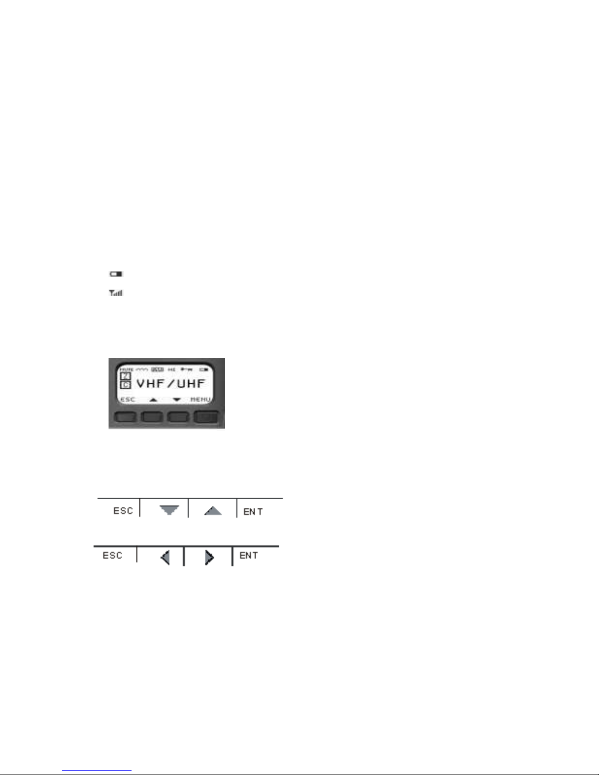
Display
On power up, the radio momentarily displays the Guardian II name and software version. The
display then indicates the operation status for the selected channel. Turn the channel knob to
select a different channel.
The display consists of various icons as shown in the figure above.
Channel type icon : Group type icon :
C
= channel
B
= bank
S
= shadow channel
Z
= zone
H
= home channel a
around a zone type means it
s is included in the zone scan list
E
= emergency
P
= priority channel
ON/OFF Volume
Channel Selector Antenna
Speaker
Accessory Jack
Alphanumeric Display
With Icons
Navigation Keys Alpha Numeric Key Pad
PTT
Collar Switches
Soft Keys
Channel Type
Group Type
a
around a channel type
means it is included in a scan list
Modulation type icon :
AW
= analog wideband
AN
= analog narrowband
DG
= digital
a
around the modulation type means some form of selective squelch is active for the channel
(NAS, CTCSS or DCS)
Other icon :
TX
= transmit channel in scan mode
RX
= receive channel in scan mode
TA
= talkaround
∩∩∩
= repeater
= encrypted
U
= unit ID call mode
= Battery Gauge
= Signal Strength Indicator
Navigation Buttons
These four buttons perform actions determined by what appears on the display.
The
MENU
button lets you access the internal software menus, toggle between a setting and its
value and save data. The
ESCAPE
(
<ESC>
) button allows you to return to a previous display
without making changes to values. The Scroll up and down buttons highlight menu choices for
selection.
The left and right scroll buttons highlight alpha and numeric characters when changing values.
Keypad
Because all channel information and switch definitions can be programmed by the PC
Programmer, the keypad is not required for basic operation of the radio. The keypad is used to
select options within the radio, or to reprogram almost any setting. It is used for DTMF signaling,
keypad programming and feature selection, among other things.
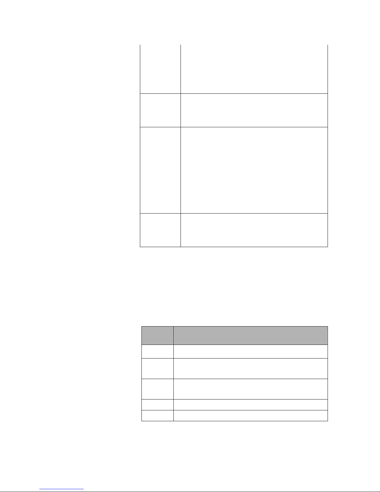
Collar Switch (three position)
The 3-position (A, B, C) collar switch located under the ON/OFF Volume control is programmed
using the PC Programmer. Ask your radio programmer how it is setup to function.

Function Description
Scan
Sets scan mode to On, Priority, or Off.
Position A: Scan, Priority scan, or off
Position B: Scan, Priority scan, or off
Position C: All scan modes off
Monitor
(includes
squelch
adjust)
Provides monitor and carrier squelch adjust functions.
Position A: Squelch adjust mode (carrier squelch only)
Position B: Monitor on
Position C: Programmed squelch mode (monitor off)
Zone
Select
Selects Zone A, B or C.
Position A: First zone assigned in current bank
Position B: Second zone assigned in current bank
Position C: Third zone assigned in current bank
Talkaround Toggles channels between talkaround and repeater
modes.
Position A: Talkaround enabled
Position B: Talkaround disabled (repeater mode)
Position C: Talkaround disabled (repeater mode)
Hi/Lo
Power
Toggles the power setting from high to low. This
setting is programmed into each individual channel
and can be the same power level.
Position A: RF Power HI
Position B: RF Power LO
Position C: RF Power LO
The radio reads the toggle switch on power-up and
periodically. Setting is retained if battery is removed.
Encryption
Enables or disables encryption. The toggle positions:
Position A: TX encryption enabled
Position B: TX encryption disabled
Position C: TX encryption disabled
Disabled
Ignores any attempted use and provides an error tone.
Collar Switch
The 2-position (o, ø) collar switch located under the channel selector and is programmed using
the PC Programmer. The most useful function of this control is to enable/disable encryption of
the selected channel.

Auxiliary Buttons
These Six programmable buttons are located on the side panel and the front (under the display) of
the radio and their use depends on how they are programmed using the PC Programmer. Ask
your radio programmer how they are set up to function.
The three most commonly used functions of these buttons are
Hi/Lo Power (useful for conserving battery life), Monitor (valuable when using analog FM
channels - also includes squelch control)
, and Next Zone.
Function Description
Hi/Lo
Power
Toggles the radio power setting from Hi to Lo. These
settings are programmed into each channel.
Monitor
(includes
squelch
adjust)
Provides monitor and carrier squelch adjust
functions.
Momentary pre : Momentarily opens squelch.
Pre and hold for 2 econd : Locks radio into
squelch open condition. To return to normal mode,
momentarily press the monitor button.
Pre and hold for 4 econd : Activates carrier
squelch adjust (on carrier squelch adjust channels
only). To return to normal mode, momentarily press
the monitor button.
Next Zone
Cycles the radio through all zones of the current
bank. The zone is stored and retained as long as the
battery is on the radio. If this is pressed and held
until an audible tone is heard the direction of Next
Zone is reversed.
Scan
Toggles the scan mode on and off.
Priority
Scan
Toggles the priority scan mode off and on. This does
not affect regular scan, which works independently.
Scan List
Add and
Delete
Toggles the channel’s scan list off and on. Affects
the current channel only.
Backlight
Toggles the radio’s backlight from off to Bright to
Dim with each key press. The backlight timer is not
affected. (The Bright+RX and Dim+RX turns the
backlight on when a signal is received)
Disabled
Ignores any attempted use and provides error tone.
Encryption
Toggles TX encryption from off to on for channels
programmed with encryption enabled. RX
encryption is unaffected. Encrypted channels can be
set by the PC Programmer to ignore this switch. The
switch has no effect on these channels (they stay
encrypted).
Home
Channel
Toggles the active channel from the Home Channel
to the currently selected channel. Normal operation
resumes on channel, zone, or bank change. This
setting can be changed using the keypad.
Keypad
Disable
To activate the key, press and hold it for 1 second.
Continue pressing to disabled the keys you want.
1 t pre : All keys enabled (front and side).
2nd pre : Keypad disabled (side keys and toggle
switch still enabled).
3rd pre : Keypad, side keys and toggle switch
disabled (PTT remains enabled).
This function can also be accessed from the keypad
by pressing and holding
<ESC>
then pressing and
holding
<ENT>
. To regain access, do these steps
again.
Talkaround
To bypass a repeater and talk directly (DIRECT,
CAR-CAR, TAC, etc.) on a repeater channel.
Toggles channel from talkaround mode to repeater
mode.
Push-to-Talk (PTT)
The Guardian II radio is normally in a ready-to-receive mode (PTT not depressed). To transmit,
press PTT and speak into the radio in a normal voice. Distance from the radio is not critical, but
2-6 inches from the radio is optimal. To return to receive mode, release PTT.
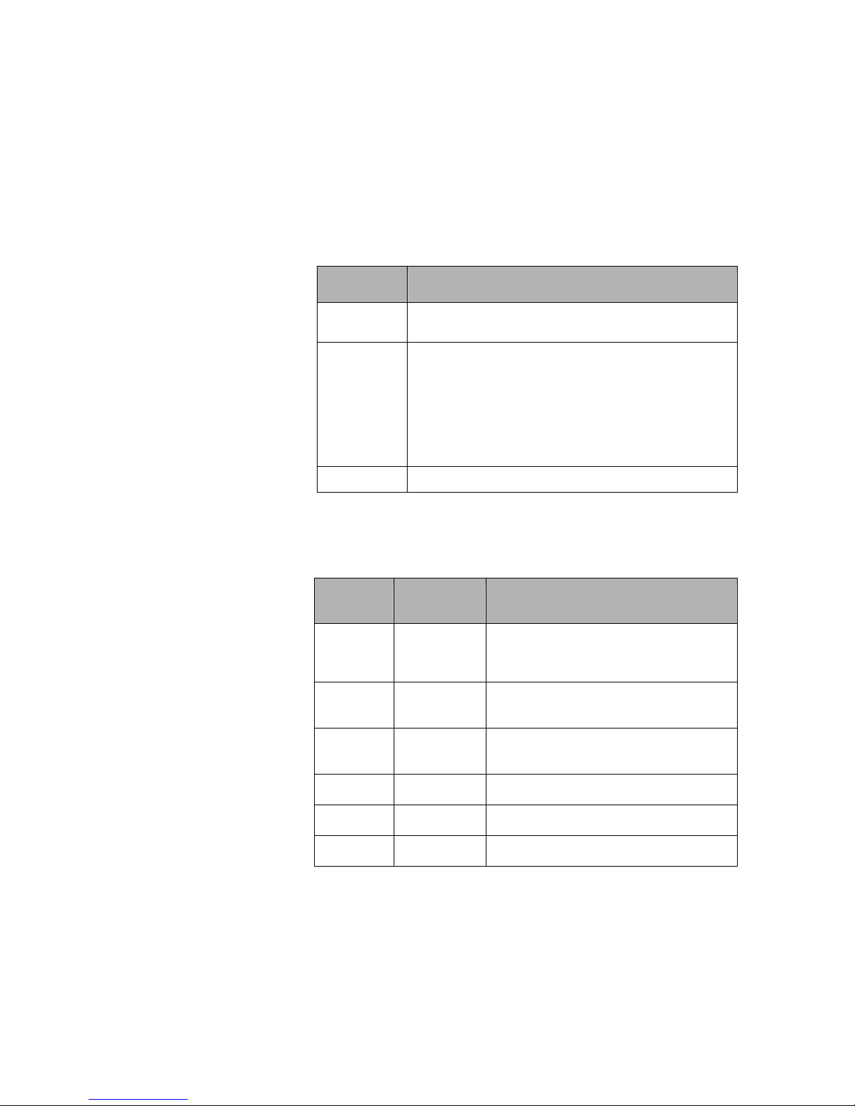
Status Indicator
The LED indicates several conditions of the radio.
Indicator Description
Red
Radio is transmitting.
Steady
Green
Radio has detected RF traffic on the channel.
Flashing
Green
Radio has detected an encrypted signal on the channel.
Internal Speaker and Microphone
The internal speaker is active when external audio accessories are not used. The internal
microphone is active when you press the PTT button.
Emergency Button
The red emergency button on top of the radio is typically used for P2 Emergency operation but
can be programmed by the PC Programmer for any of the following functions. Ask your radio
programmer how it is set up to function.
Function Description
Disabled
Ignores any attempted use and provides an error
tone.
Emergency
Mode
The emergency channel is programmed by the PC
Programmer or from the radio keypad. If left unused,
the current channel serves as the emergency channel.
In P2 mode the emergency bit is set. Since analog
modes have no similar function, the radio performs
an open-mic function for the duration and interval
programmed by the PC Programmer.
Zeroize
Erases all encryption keys in the radio.
Alert Tones
Audible tones provide important information about the radio’s operating state or condition.
Tone
Pitch
Tone Length
Description
Low
Burst
Error pressing button, failed self-test,
talk time out warning or empty
channel.
Low
Steady
Talk time out, talk inhibit, invalid
mode or radio locked.
Medium
Burst
Button press, passed self-test or
receiving in clear voice.
Medium
Pulsed
Emergency call mode or key error.
High
Burst
Low battery.
High
Pulsed
Individual call.
Backlight
The backlight is illuminated when a signal is received (if programmed by the PC Programmer). It
is activated from an auxiliary button (toggles through settings) on the radio or from the keypad
There is a slight reduction in battery life if using the backlight, but not significant. The power
drain difference between dim and bright is negligible.

3: OPERATING THE RADIO
The Guardian II operates with most of its features already programmed into the radio. Request a
list of the functions that are assigned to the buttons and switch on your radio.
Quick Start
Before proceeding, the radio must be set up using the Guardian PC Programmer. If necessary,
refer to Chapter 2, Controls and Indicators.
1.
Battery
Install a charged battery.
2.
Antenna
Install the correct antenna for the frequency
being used. Do not operate the radio without
an antenna.
3.
Power-up
Turn the power-volume knob clockwise about
halfway around. Set the volume to a
comfortable level when a transmission is
heard. A -10 second delay at power-up is
normal.
4.
Select
channel
Turn the channel knob until the desired
channel is shown on the display.
5.
Receive
Listen using the built-in speaker. Note: the first
volume knob click position mutes the speaker.
6.
Tran mit
Press
PTT
and speak about 4 inches from
microphone. Release
PTT
when finished
speaking. Do not press
PTT
longer than
necessary after talking.
Selecting Channels
Use the rotary channel selector to select the desired operating channel. Changing Zones also
makes other preprogrammed channels available for use. (See Zone Select)
Selecting Shadow Channels
The Guardian II can be programmed to detect any type of analog FM signals and any
combination of P2 digital signals, up to 9 sets of analog/digital settings. This is done with the
use of shadow channels. Once received, the radio is programmable to transmit either in kind or
strapped to its channel selector.
This mix-mode of operation enables digital systems to seamlessly integrate into older analog
systems. The preferred signaling mode can be set up for a P2 digital signal, be able to receive
any analog signal and respond back to the operator on the analog radio.
Applications
Some applications that are available using shadow channels are:

•
Simultaneous analog and digital operation
•
CTCSS (or DCS) picklists used to choose repeaters
•
P2 NAC picklists used to choose repeaters
•
Multiple encryption use
•
Supervisory talkgroups
Accessing Shadow Channels
Note:
Shadow channels must be programmed into the radio to access them. For information on
programming shadow channels,
refer to “Adding a Shadow Channel” on page -1 ).
From the keypad, select shadow channels by pressing * then the appropriate shadow channel
number (for example, pressing *3 selects shadow channel 3). Return to the primary channel by
pressing **, *0, or
<ESC>
.
A talkback timer allows you to transmit within 10 seconds on the shadow channel. The timer is
reset at the end of each received message. When a transmission is received on a shadow channel,
an
S
displays as the channel type.
Selecting Home Channel
If a button is programmed with a home channel, press the assigned home button. The home
channel status displays. To assign a different home channel, access the main menu
(refer to
“Home Channel” )
Selecting a Zone
If one of the auxiliary buttons is programmed for Next Zone, press that button to toggle through
the zones. If the 3 position collar switch is programmed for Zone Select, rotate the switch to
select the desired zones. A zone is also selectable by accessing the main menu
(refer to “Select
Menu”)
.
Selecting a Bank
If one of the auxiliary buttons is programmed for Next Bank , press that button to toggle through
the Banks. Banks are selected by accessing the main menu
(refer to “Select Menu”)
.
Selecting Talkaround
Talkaround forces the transmit frequency to an equal receive frequency for a selected channel.
This is useful for direct radio-to-radio communication when a repeater is unavailable. If a button
or switch is programmed for talkaround, press the assigned button or position the toggle switch
appropriately. Talkaround is turned off and on by accessing the main menu
(refer to “Select
Menu”)
.
Adjusting Analog Carrier Squelch
If an auxiliary button is programmed to access the squelch adjust (Monitor), press the button for
at least 4 seconds until the squelch adjust status displays. Use the scroll buttons to change the
squelch setting. Press <
ESC>
to save the value and return to normal operation.
Squelch is also adjustable from the main menu
(refer to “Channel Submenu”)
.

Transmitting
Press the
PTT
button and speak normally about four inches from the microphone. Release the
PTT
button when finished speaking. Do not hold the
PTT
longer than necessary after talking. Channels
programmed for receive-only sound an alert tone, display
RX
ONLY
, and do not transmit.
Your radio may be setup with the Transmit Inhibit feature. This feature locks the PTT switch to
keep users from talking over other radio conversations. It can also be setup to allow you to
transmit over the signal anyway if the PTT switch is pressed twice within approximately ½
second. The transmit inhibit settings are accessed from the main menu
(refer to “Global
Submenu”)
.
Your radio may be set up with the Transmit Timeout feature that shuts the transmitter down after
a pre-determined time. This is useful for preventing long transmissions when PTT is accidentally
pressed. Transmit timeout defaults to off, but can be programmed from 0 minutes (off) to
minutes, in 30 second increments (
refer to “Global Submenu”).
Scanning
Scanning is available on the Guardian portable at a rate of about
8 channels per second. Various types of scanning exist. The radio can be programmed to talkback
on the received channel or on the currently selected channel.
Guidelines
To maximize the efficiency of scanning channels, use the following guidelines:
•
Keep the number of channels in a scanlist to the minimum required. Since the radio scans
at about 8 per second, each channel is scanned faster if there are fewer channels to scan.
•
If scanning channels with noise squelch settings, higher carrier squelch values provide
faster results (improvements above values of 8 are minimal), but higher squelch values
reduce effective range.
•
If scanning multiple channels with the same frequency (regardless of squelch values), use
shadow channels when possible. A primary channel with all its shadows still scans at the
rate of about 8 per second.
Setup
1.
Create a scan list. Display the channel to include in the scan list. Use the scan list add/delete
button to toggle channels on/off the scan list. A square around the
C
indicates the channel is
in the scan list. To remove the channel from the scan list, press the left scroll button. The
square around the
C
is cleared.
To add a zone to the zone scan list, set the radio to the zone to include in the scan list. Press
and hold the scan list add/delete button to toggle the selected Zone on/off the Zone Scan List.
A square around the
Z
indicates the zone is in the scan list.
2.
Select a scan mode. The mode is preprogrammed into the radio but you can verify or change
it using the keypad.
Refer to “Scan Menu”.
The modes are normal scan, scan zones in the scan
zone list or scan all frequencies programmed into the radio.
3.
Activate scan. Use one of the following methods:
•
Use the preprogrammed auxiliary button
•
Use the preprogrammed collar switch, or
•
Access the main menu
(refer to “Scan Menu”)
The selected mode of scanning is evident by the display. Examples are:
SCAN****

ZONE****
SRCH****
Priority Scanning
Priority scanning is independent of regular scanning and allows you to sample a priority channel
at various rates while listening to another conversation. It is not necessary to be scanning to
monitor a priority channel. Up to 2 priority channels can be selected.
Priority scan breaks into actively received signals at a priority interval rate setup in the PC
Programmer or through the programming menu.
Priority scanning is set up by creating a priority scanlist, selecting a priority mode and activating
priority scan.
1.
Create priority channels. While you can have up to two priority channels, one is
recommended. This is programmed into the radio but can be changed by accessing the main
menu. To select priority channels from the menu,
refer to “Scan Submenu”).
2.
Select the priority scan mode. This is programmed into the radio from the PC Programmer. It
is highly recommended to leave this at its default value (PR1), unless it is absolutely
necessary to scan two priority channels. To change this mode using the keypad,
refer to “Scan
Menu”).
3.
Activate priority scan. Several options exist for turning priority scan on or off.
•
Use the preprogrammed auxiliary button
•
Use the preprogrammed collar switch
•
Use the keypad (
refer to “Scan Menu”).
You know you are scanning when the top row of the display briefly flashes one of the
following:
canP1**
canP1P2

4: OTHER STANDARD FEATURES
Cloning Radio to Radio
Note:
The cloning described in this section is for standard radios. If you have a radio equipped
with the Fire Features option, refer to Chapter 8.
Radio to radio cloning enables the transfer of channel settings from one radio into another radio.
Information that is cloned:
•
All channel settings
•
Channel assignment to zones
•
Zone assignments to banks
•
Special function channels and assignments
Information that is not cloned:
•
Encryption keys
•
Passwords
•
P2 Unit ID
•
uxiliary button functions
•
Toggle switch functions
•
Emergency switch functions
•
Other global parameters
Note:
Do not turn radios off or disconnect cable during cloning process.
To clone one Guardian II portable radio to another:
1.
Turn off both radios.
2.
Connect One end of the Source End of the clone cable to the source radio. (the radio with the
information to be cloned).
3.
Connect the other end of the cloning cable to the side connector of the target radio
Note:
Guide the top and bottom pegs on the end of the cable into the corresponding slots on
the radio’s side connector. When they click together, use your thumb to hold the cable to the
radio and turn the screw handle until the cable is tight against the radio.
.
Turn on the target radio and the source radio. The source radio indicates the cloning
mode.
6.
Press PTT on the source radio. Banks 1 to 4, with all of their zones and channels, are sent to
the target radio. The source radio can then be used to clone another radio.
DTMF Dialing
DTMF dialing transmits (including sidetone) the DTMF tone that corresponds to a pressed key. It
is used primarily for:

•
Entering a repeater code for access to a repeater.
•
Accessing a repeater with a phone patch to dial a phone number.
•
Accessing remote weather stations using DTMF tones A, B, C, and D by pressing the
corresponding navigation keys.
To access while in any analog mode, press the PTT button and the desired key.
Table of contents


