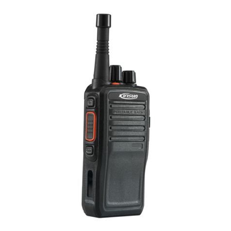
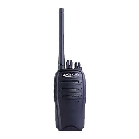
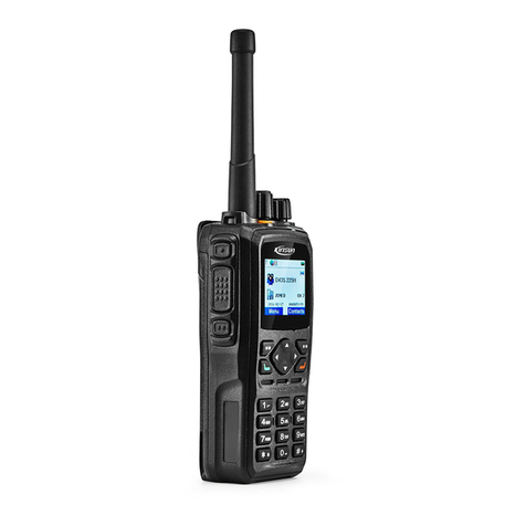
Kirisun PT6500 User manual

PROFESSIONAL
TWO-WAY RADIO
PT6500
V071208
FM PORTABLE RADIO
SERVICE MANOAL
Welcome

1
DANGEROUS!!
WARNING
STATEMENT
Do not connect the AC power or DC power over 7.4V with
any connector or terminals of the radio. Otherwise it will
cause fire, electric shock or damage to the radio.
Do not reverse power connection.
It may cause harm to the radio if signal input on the antenna
connector is bigger than 20 dBm (100mW).
Do not turn on the power before the antenna or load
connection is completed.
If the antenna has been damaged, do not use the radio.
Damaged antenna may cause lightly burning on skin.
Though the radio is waterproof, it's better to avoid putting it
in rain or snow, or any other liquid to ensure its life and
performance.
Kirisun Electronic (Shenzhen) Co., Ltd owns the copyright of
KSP6500 software.
Unauthorized Duplication of KSP6500 software is strictly
prohibited.
Kirisun Electronic (Shenzhen) Co., Ltd owns the copyright of
the MCU software.
Kirisun Electronic (Shenzhen) Co., Ltd owns the copyright of
the radio outward/structure/circuit design.
Kirisun Electronic (Shenzhen) Co., Ltd owns the copyright of
this service manual. Unauthorized publication is prohibited.
Kirisun Electronic (Shenzhen) Co., Ltd owns the trademarks
KIRISUN , , .
PT6500 SERVICE MANUAL
CONTENTS
Chapter 1 Introduction.......................................................................2
Chapter 2 Radio Overview and Function Keys.................................2
Chapter 3 Electrocircuit.....................................................................3
Chapter 4 Function Description and Parameter Setting....................7
Chapter 5 Service Assemble and Disassemble..............................12
Chapter 6 Radio Debugging............................................................14
Chapter 7 Major Specifications.......................................................18
Chapter 8 Trouble Shooting............................................................18
Appendix 1 Abbreviations................................................................19
Appendix 2 Spare List.....................................................................19
Appendix 3 Electronic Component List...........................................20
Appendix 4 Framework Component List.........................................20
Appendix5 Accessory List...............................................................31
Figure 1 PT6500 Top Main Board Position Number Diagram.........32
Figure2 PT6500 Bottom Main Board Position Number Diagram....33
Figure 5 .........36
Figure 6 ....37
Figure 7 38
Figure 8 ....38
Figure 9 PT6500 Schematic Circuit Diagram(136-174MHZ) .........39
Figure 10 PT6500 Schematic Circuit Diagram(400-470MHZ) ...... 40
Figure 11 PT6500 Main Board Schematic Circuit Diagram ...........41
Figure 12 PT6500 Keyboard Schematic Circuit Diagram...............42
Figure 13 PT6500 PTT Board Schematic Circuit Diagram.............43
Figure 3 PT6500 Top Main Board Position Number Diagram.........34
Figure4 PT6500 Bottom Main Board Position Number Diagram....35
PT6500 PTT Top Board Position Number Diagram
PT6500 PTT Bottom Board Position Number Diagram
PT6500 Top Keyboard Schematic Circuit Diagram..........
PT6500 Bottom Keyboard Schematic Circuit Diagram

2
Chapter 1 Introduction
1.1 Introduction
This manual applies to the service and maintenance of PT6500
series of FM portable radios, and is designed for the engineers and
professional technicians that have been trained by Kirisun. In this
manual you can find all the information of product service. Kirisun
reserves the rights to modify the product structure and specification
without notice in order to enhance product performance and quality.
You can also log on our website www.kirisun.com to download the
latest service manual or contact your local dealer or us.
Read this manual before repairing the product.
1.2 Service Precautions
Safety
Avoid skin contacting with the antenna connector and PCB.
Do not reverse the power polarities.
If signal input at antenna connector is bigger than 20dBm(100mW),
it may cause damage to the radio.
Do not turn on the power before the antenna and load connection is
completed.
Do not use the radio if the antenna has been damaged. Contacting
the damaged antenna will cause slightly burning on the skin.
Electromagnetism Interference
It's prohibited to use or repair the radio in the following places:
Hospital, health center, air port
Any area with a potentially explosive atmosphere (where the air
contains gas, dust and smog, etc.), such as the storage or
transportation facilities of fuel or chemicals.
Any area of dynamite or exploder.
It's recommended to avoid using or repairing the radio in the
following places:
It's recommended to avoid using the radio in a car that is moving.
The radio wave might interfere the auto engine and cause it to stop
working.
Component Replacement
All the components used in repair service should be supplied by
Kirisun.
Other components of the same models available on the market are
not surely able to use in this product and we do not guarantee the
quality of the product using such components.
Please fill in a component application forms if you want to apply for
any components from Kirisun.
The following is one sample form that might be used to apply for
any components from Kirisun.
Component Application
1.3 Service
All the Kirisun products are subject to the service warranty.
The main unit of the radio is guaranteed for free service of 24
months. Accessories (such as battery pack, power adapter, antenna
or charger) are guaranteed for free service of 6 months. Earphones
are wearing parts and out of warranty.
In one of the following situations, charge free service will not be
available.
No valid service warranty or original invoice.
Malfunction caused by disassembling, repairing or reconstructing
the radio by the users without permission.
Wearing and tearing or any man-made damage such as
mechanical damage, burning or water leaking.
Product serial number has been damaged or the product trademark
is difficult to identify.
After the warranty expires, lifetime service is still available. And we
also provide service components to service stations and service
staff.
Chapter 2 Radio Overview and Function Keys
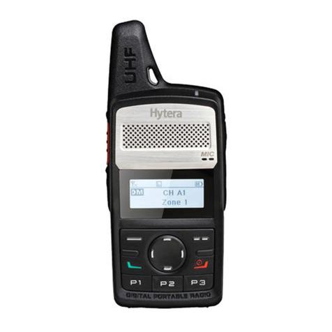
2.1 Radio Overview
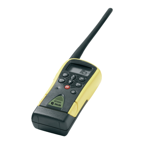
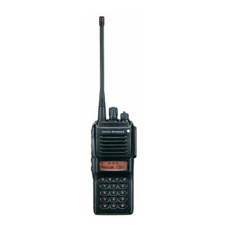
The functions of the components are as follows:
A. LED Indicator
Lights red while transmitting;
Lights green while receiving.
123
456
789
*0#
P
1P
2P
3P
4
B. Power/Volume Switch Knob
Turn clockwise till a click is heard to switch on the radio.
Turn counterclockwise till a click is heard to switch off the radio.
Rotate to adjust the volume after turning on the radio.
C. Channel Selector
Rotate to select the channel 1-128.
D. Antenna
E. Top Button (programmable button)
It is recommended to be set as the emergency warning Button.
F. Side button 1 (programmable button)
G. PTT PUSH-TO-TALK :
To make a call, press and hold the PTTbutton, then speak into the
microphone with normal voice. Release the PTT button to receive
signals.
H. Side button 2 (programmable button)
I. Button
Return and delete button in the menu.
J. Button
Select Button.
K. Button
Select Button.
L. Button
Enter and Confirm Button.
M. Numeric keypad
N. Microphone/speaker jacks
P1
P2
PT6500 SERVICE MANUAL
Parts and Spare Parts Requisition
Radio
ModelComp
onent Position
Mark Model/
Specifications Material
Serial number Qty
PT-6500(400
-470MHz)
Field eff-
-ect tube Q3 RD01MUS1 105-RD01MU-R01 1
1
PT-6500(400
-470MHz) Triode Q49 2SC5108(Y) 104-SC5108-R01
P3
P4

1
1
2
2
3
3
4
4
D D
C C
B B
A A
Title
Number RevisionSize
A4
Date: 2007-7-26 Sheet of
File: X:\PT6500\.. \PLL.SchDoc Drawn By:
PLL-LE
PLL-CLK
PLL-DA
PLL-UL
PLL IC
IC2
QT TCXO
5C
LOOPFILTER
RIPPLE
FILTER
VCO
Q6
BUFF
Q5 Q4
RF AMP
5C Q14
ADF4111
MOD
12.8MHz
X1
TCXO
5C
TX
VCO
Q11
RX
Q8
BUFF
5C
1
1
2
2
3
3
4
4
DD
CC
BB
AA
Title
Number Revisio nSize
A4
Date: 2007-7-26 Sheet of
File: X:\PT6500\..\Receiver.SchDoc Drawn By:
MCF
51.65MHz IF SY STEM
CF1
450KHz H
CF2
450KHz F
X3 multiply
AF AMP
TCXO
12.8MHz
AK2346
BPF
RF AMP
BPF
ANT SW
ANT
IC7
MCU 1st Local OSC
D1 D39 D7 D8 Q18 Q19
IC4
IC6
IC9 TDA8541
3
The receiver's first local oscillation is generated by the frequency
synthesizer. The second local oscillation adopts the 4th harmonic
51.2MHZ of TCXO.
The transmitter signals are generated by frequency synthesizer.
The reference frequency of frequency synthesizer is generated by
TCXO.
3.2 Receiver (RX) Illustration
Figure 3.2 Receiver Illustration
The Receiver Front Terminal
Signals from the antenna pass through the RX/TX switch (D1, D39,
D7, D8); and then undesirable out-of-band signals will be filtered
out at the band pass filter (BPF) consisting of two-stage LC; then
signals are amplified at the low noise amplifier (LNA) consisting of
Q18 and its peripheral components.
The output from the LNA passes the BPF consisting of three-stage
LC for filtering and then is sent to the first grade frequency mixer
(Q19).
AGC Circuit
The AGC circuit consists of Q17 and its peripheral components.
Only when the input signal is too large can the AGC functions to
reduce the Q18 plus.
The First Frequency Mixer
After mixing the receiving signals for LNA and the first local
st
oscillation signals from the frequency synthesizer, the 1 IF signals
(51.65MHz) are generated.
IF Circuit
st
Signals of adjacent channel and those out of band of the 1 IF
signals are filtered via the crystal filter (XF1).
st
The 1 IF signals fromthe crystal filterare amplified atthe first
IF amplifier (Q20), and then are sent to the IF processing IC
(IC4, TA31136).
nd nd
The IF IC consists of the 2 frequency mixer, the 2 local oscillator,
IF amplifier, limiter, phase frequency detector, and noise amplifier.
nd
The 2 local oscillation is obtained after 12.8MHz signals from X1
are amplified via Q15 and external circuit. The 2nd local oscillation
st
(51.2 MHz) and the 1 IF signal (51.65 MHz) are mixed at IC5 to
generate the 2nd IF (450 kHz). After the 2nd IF signal is amplified
and its amplitude is limited at IC4, and then filtered at porcelain filter
(CF1 or CF2, 450 kHz), IC5 demodulates and sends out audio
signals.
nd
The 2 IF filter selector circuit consists of CF1, CF2, D18, D19 and
peripheral circuits, when the radio is set to broad band, CF2 is open,
CF1 is closed and CF2 functions; when the radio is set to narrow
band, CF1 is open, CF2 is closed and CF1 functions.
Squelch Circuit
Demodulation output from IC4 is sent to the noise amplifier in Ic4.
After being amplified, noise signal is sent to D21 for further
amplification and to D22 for wave checking and then sent to MCU,
which determines the noise volume to control the squelch. This
voltage is inversely proportional to the input signals.
3.3Transmitter (TX) Illustration
Transmitter Power Amplifier
The modulated signals from VCO are amplified at Q2, Q4, Q59, Q5,
Q3, and then sent to Q1 for power amplification. Q1 output power:
4W.
The Q1 and Q3 gate offset is controlled by APC circuit. Transmitter
output power can be controlled conveniently by changing the gate-
offset.
APC (Auto Power Control) Circuit
R57, R65 and R66 are the amplifier current checker, IC3A is the
sample amplifier of the amplification current; .IC3B is the power
comparison amplifier.
If the transmitter output power is too big, the amplifier current will
increase, IC3A output will mount, IC3B output voltage decrease, the
offset voltage added to Q1 and Q3 will decrease, and then the
transmitter output power will decrease. Vice versa, such can ensure
steady transmitter output power in different working circumstances.
MCU changes the input power to IC3B to set the power.
3.4 Frequency Combiner Illustration
Figure 3.4 Frequency Combiner Illustrations
This radio adopts phase locked loop (PLL) type frequency combiner.
The frequency combiner consists of the reference oscillator, voltage
controlled oscillator (VCO), programmable frequency divider, phase
PT6500 SERVICE MANUAL
1
1
2
2
3
3
4
4
D D
C C
B B
A A
Title
Number Revisi onSize
A4
Date: 2007-7-26 Sheet of
File: X:\PT6500\.. \Frequency confi guration.SchDocDrawn By:
ANT
ANT SW RF AMP MCF
51.65MHz IF SYSTEM
CF1
450KHz H
CF2
450KHz F
X3 multi ply
AK2346
AF AMP
TCXO
12.8MHz
MIC AMPPLL VCOTX AMPPA AMP
RX
TX
Chapter 3 Electrocircuit
3.1 Frequency Configuration
Figure 3.1 Frequency Structure
This radio adopts the 2nd Mixer, the 1st IF 51.65MHz, the 2nd IF
450kHz.
1
1
2
2
3
3
4
4
D D
C C
B B
A A
Title
Number RevisionSize
A4
Date: 2007-7-26 Sheet of
File: X:\PT6500\..\T X.SchDoc Drawn By:
RF AMP
5T 5R
Q4 Q5 Q3
DRIVE
DRIVE
PRE
5T 5T
APC
Q12
ANT SW LPF
APC CONTROL
IC3
TX/RX SW
Q1
RF POWER
APC
5T
SW
BATTARY
7.5V
VCO
ANT
Figure 3.3 Power amplifier and antenna switch schematic diagram

4
comparator, and the upper limiting filter.
Q6, D2, D4, D5 and D6 constitute the transmitting VCO unit. D9 is
the modulating circuit of the transmitting VCO.
Q11, D11, D12, D13 and D14 etc. constitute the receiving VCO
unit.
IC2 (ADF4111) is the PLL integrated circuit, which can comprise
the programmable reference frequency divider, programmable
frequency divider, phase comparator and charge pump, etc.
The upper limiting filter consists of R43 and C96 etc.
The frequency reference is provided by X1 (TCXO, 12.8MHz).
The frequency reference from TCXO (temperature control crystal
oscillator) receives frequency division by the programmable
reference frequency divider in IC2 to generate the frequency
reference of 5kHz or 6.25kHz (according to the frequency of the
channel, controlled by MCU).
The oscillation frequency from VCO is sent to IC2, after frequency
division by the programmable frequency divider, it is compared
with the frequency reference to get the error signal, which is, after
wave filtering by the upper limiting filter, sent to VCO to change
the oscillation frequency of VCO, which allows the VCO frequency
to achieve the set value and the VCO to be locked.Detection of
loss of lock: if PLL loses lock, IC2 pin14 outputs low level signal to
MCU, which prevents the transmitter from transmitting and
generates alert.
Q13 and related circuits are used for switching the upper limiting
filter.
3.5 Audio Processing Circuit:
I
C6 (AK2346) is a special voice processing chip provided with
functions like amplification, wave filtering, preemphasis,
deemphasis, scrambling, companding and MSK MODEM etc. Most
voice processing tasks of the radio are completed by it.
MIC Signal Processing:
Voice signals from MIC are controlled by AGC circuit, and then
reach IC24, one group of signals are amplified at IC24B (VOX
circuit) and are processed into direct current by D35 and sent to
MCU for processing; the other group of circuits are amplified at
IC24A and then receive amplification, wave filtering, companding
(optional), preemphasis, scrambling and amplitude limit at IC6 pin3,
after that, they are exported from IC6 pin7 and sent along with
CTCSS/DCS to VCO for modulation.
2T/5T signals are imported from IC6 pin6, and after amplitude limit
and amplification, they are exported form IC6 pin7 and sent to VCO
for modulation.
Receiver Audio Signal Processing:
Voice signals exported from IC4 are divided into two channels, one
comes to the low pass circuit (voice signals filtered) consisting of
IC5, etc for amplification and wave filtering to get comparatively
pure CTCSS/DCS signals, which are then sent to MCU for
processing; the other comes to IC6 pin23, after amplification and
wave filtering, one channel is exported from IC6 pin21 (DTMF/2T/5T
signals etc.), DTMF/2T/5T signals etc. come through the high pass
circuit (sub-audio signals filtered) consisting of Q30 and Q31 etc.,
DTMF signals come to IC10 (special chip for HT9172 DTMF
decoding) for decoding and then sent to MCU for processing, 2T/5T
signals are sent to MCU for processing after wave filtering and
waveform modification by IC1; the other channel of signals (voice
signals) are exported form IC6 pin18 after scrambling, preemphasis,
deemphasis and companding and then imported from IC6 pin19 for
amortizing and amplification before being exported form IC6 pin20.
IC13 is a voice storage chip, which stores voices including channel
prompt etc., each time the channel is changed, the speaker will
prompt the current channel number by voice. Press the voice
prompt key to prompt the current channel number again.
Receiver audio signals, voice prompt signals, 2T/5T/DTMF signals,
prompt voice signals, emergent alert signals are gathered to be
amplified by the audio frequency amplifier IC9 to drive the speaker.
Speaker impedance: 16Ù.
Note: None of the terminals of the speaker can be grounded!
The volume of emergent alerts cannot be controlled.
3.6 Power Supply:
The radio is equipped with 7.4V battery as power supply, which
directly supply power to transmitter power amplifier circuits (Q1, Q3)
and receiver audio power amplifier (IC9), other circuits adopts
regulated 5V power supply.
Q40, Q45: 5V low voltage difference, micro power regulator.
Q43: 5T switch, controlled by MCU.
5T: Supplies power for the front terminal of the transmitter.
Q39: 5R switch, controlled by MCU.
5R: Supplies power for the receiver RF amplification, mixing, IF
processing, audio signal processing..
Q44: 5C switch, controlled by MCU.
5C: The 5V power controlled by power saving supplies power for
the frequency synthesizer.
3.7 MCU:
MCU controls the working of each unit of the radio to realize
all the radio functions.
Connects with the PC
Accesses the current channel status data
Controls the PLL to generate receiver and transmitting local
oscillation frequency
Acquires current channel status
Controls the LED status indication
Controls the power supply of each location
Checks the action of each function key
Generates CTCSS signals
Generates DCS signals
Generates power control signals
CTCSS decoding
DCS decoding
Squelch check and control
Controls the content of voice indication
Memorizes the radio channel data, CTCSS/DCS data, and other
data of function setting and parameter adjustment.
CTCSS/DCS Encoding and Decoding:
2
Memorier (E PROM, AT24C256)
PT6500 SERVICE MANUAL
1
1
2
2
3
3
4
4
D D
C C
B B
A A
Titl e
Number Revi sionSiz e
A4
Date: 2007-7-26 Sheet of
Fil e: X:\ PT6500\..\ AUDI O.SchDoc Drawn By:
pin 7 Q30
HP Q31
HP
IC1A
HP AMP
IC1B
IC10
HT9172
IC5A IC5BIC5CIC5D
AMP LP LP AMP CTCSS/ DCS
DTMF
2T
AK2346
IC6
IC4 pi n 9
AF AMP
IC9 TDA 8541
pin 20
MIC AMP
MCU
IC7
pin 23
pin6
pin3
MIC
SP
Figure 3.5 Audio Processing Diagram

5
047 134 245 365 516 712
051 143 251 371 532 723
054 152 261 411 546 731
065 155 263 412 565 732
071 156 265 413 606 734
072 162 271 423 612 743
073 165 306 431 624 754
074 172 311 432 627
PT6500 SERVICE MANUAL
No. Frq [Hz] No. Frq [Hz] No. Frq [Hz] No. Frq[Hz]
186.2
1 67.0 11 94.8 21 131.8 31
192.8
2 69.3 12 97.4 22 136.5 32
203.5
3 71.9 13 100.0 23 141.3 33
210.7
4 74.4 14 103.5 24 146.2 34
218.1
5 77.0 15 107.2 25 151.4 35
225.7
6 79.7 16 110.9 26 156.7 36
233.6
7 82.5 17 114.8 27 162.2 37
241.8
8 85.4 18 118.8 28 167.9 38
250.3
9 88.5 19 123.0 29 173.8 39
10 91.5 20 127.3 30 179.9
DCS signaling:
DCS (Digital code squelch) is a kind of continuous digital code
modulated with voice signals on carrier wave to control squelch. If
DCS function is enabled, only in case the same DCS code is
received can the speaker be turned on so as to avoid interference
from useless signals.
83 groups of standard codes (positive and inverse code) are
available. See table 2.
DCS signals generated by MCU (PWM wave shape) pass the low
pass filter to be filtered off the high frequency over 300Hz and then
are sent to VCO and TCXO for modulation. VCO modulates the
high frequency of DCS signals; TCXO modulates the low frequency
of DCS signals.
CTCSS/DCS signals from the receiver are sent to MCU for
modulation. MCU determines whether the DCS encoding of the
receiving signals is identical with that set on the radio and decides
whether to turn on the speaker.
CTCSS/DCS signals generated by MCU (output form pin24 and
pin28, PWM wave), are respectively sent to VCO and TCXO for
modulation.
CTCSS/DCS signals from the receiver are sent to MCU (pin1) for
demodulation. MCU determines whether the signals contain the
same CTCSS/DCS as that set on the radio and decides whether to
turn on the speaker.
CTCSS
CTCSS(continuous tone control squelch system, sub-audio for abbr.)
is a squelch control system modulated on carrier wave with
continuous sub-audio frequency as pilot frequency. If a channel is
set with CTCSS, only when both the CTCSS of the receiver and
that of the transmitter are identical, communication is available,
which avoids interference of other signals.
This radio is equipped with 39 groups of standard sub-audio
frequencies for your selection as shown in
Table 1
CTCSS signals are generated by MCU (PWM waveform) and are
sent to VCO for modulation via upper limiting filter consisting of RC,
which filters high-frequency components over 300Hz.
Table 3.1 CTCSS Frequencies
3.8 Semiconductor Components
MCU Description
Table 3.3 Microprocessor (M30620) Port Description
I/O
O
O
I
O
O
-
-
O
O
I
O
-
I
-
-
I
O
O
O
O
O
O
-
O
O
O
-
O
O
O
-
-
-
O
O
O
O
O
-
I
Port Name
VCCN
TONEO
TONEI
E-SDA
E-SCL
C-BYTE
C-CNVSS
SHIFT
E-TEST
RESET
XOUT
VSS
XIN
VCC
CMMI
INTO
A-RDT
A-TCLK
A-SCLK
A-DI/O
A-TDATA
A-DIR
NC
QT VCO
PLL-LP
PC/TV
NC
QT TCXO
C-TXD1
C-RXD1
C-CLK1
NC
ICA
PABC
APC2 SW
APC1 SW
RX SW
TX SW
C-HOLD
PLL-UL
Function
PLL frequency reference adjustment
2T/5T/DTMF/BEEP signals inout
2T/5 signals input
EEPROM data cable
EEPROM clock cable
Grounding
Grounding
Clock offset H: Clock offset
EEPROM write-protection pin
H: Unwriteable L:Writeable
Reset pin
Clock output pin
Grounding
Clock input pin
Connects to 5V power supply
Grounding
AC dump detecting pin
AK2346 control pin
AK2346 control pin
AK2346 control pin
AK2346 control pin
AK2346 control pin
AK2346 control pin
Blank
CTCSS/DCS output pin (to VCO modulation)
Phase locked loop upper limiting filter switch
H: switching overmedium frequency points
Power control or receiver band pass tuning
voltage control
Blank
CTCSS/DCS output pin (to TCXO modulation)
Serial data output, communicates with PC
Serial data input, communicates with PC
Grounding
Blank
Upstage power amplifier power supply control
H: Transmitting
power amplifier control switch
H:transmission
power amplifier control switch L:transmission
Receiver VCO power switch L: Receiving
Transmission VCO power switch L:transmitting
Grounding
Phase locked loop unlocked detection pin
PIN
1
2
3
4
5
6
7
8
9
10
11
12
13
14
15
16
17
18
19
20
21
22
23
24
25
26
27
28
29
30
31
32
33
34
35
36
37
38
39
40
Table 3.2 DCS Encoding List
023 114 174 315 445 631
025 115 205 331 464 632
026 116 223 343 465 654
031 125 226 346 466 662
032 131 243 351 503 664
043 132 244 364 506 703

6
Type
Ht9172
PST9140NR
TC75W51FU
ADF4111
NJM2904
Ta31136
NJM2902
AK2346
M30620
AT24C256
TDA8541
RQA0002
DTC144EUA
2SK508NV
DTA144EE
DTA144EE
2SC4116
2SC4617
2SC5108
DTC144EE
2SK1829
3SK318
3SK318
2SC5108
2SC5108
2SC4617
DTC144EE
DTC144EE
DTC144EE
DTA144EE
DTA123JE
2SK1824
RD01MUS1
2SC4617
2SC4617
DTC144EE
2SK1824
2SK1824
DTC144EE
DTA144EE
2SK1824
2SA1586
ST2301
2SC5108
XC6024B502MR
2SC4116
DTC144EE
ST2301
DTA123JE
XC6024B502MR
2SA1586
ST2302
2SC5108
2SC3356
2SK1824
2SK508NV
DTA143TE
2SC5108
DTA143TE
Function Description
DTMF decoding chip
MCU reset circuit
MIC amplification, amplitude limit and filtering
Frequency combiner
APC, voltage comparison, driving
nd nd
Receiver 2 local oscillation, 2 IF amplification,
Amplitude limit, demodulation, noise amplification
Receiver demodulation signal amplification, filtering
Audio processing chip
MCU
2
E PROM, storage channel frequency data, function
setting parameters, debugging status parameters
Receiver's audio power amplifier
Remitter's upstage power amplifier
APC control switch
Receives VCO oscillation circuit
APC output switch
APC control switch
PLL low pass switch
VCO power filter
nd
Receiver's 2 local oscillation doubling circuit
APC control switch
Receiver's HF amplification gain control switch
Receiver's HF amplification
st
1 frequency mixer
VCO buffer amplifier
st
1 IF amplifier
Receiver's noise amplifier
Red LED drive
Wide and narrow band noise switch
Green LED drive
Wide and narrow band frequency discrimination switch
2T high pass filter control switch
Transmitter power amplifier pushing
2T high pass filter circuit
Beat frequency control switch
Receiver's mute switch
Receiver's audio output switch, off upon emergent alert.
Audio power amplifier control switch
MIC amplification unit power switch
Voice prompt switch
External PTT detection switch
5R switch
VCO buffer amplifier
5V regulated voltage output
MIC AGC control switch
External PTT detection switch
5T switch
5C switch
5V regulated voltage output
MIC AGC control switch
External horn control switch
Transmitter's 1st amplification
nd
Transmitter's 2 amplification
Receiver's audio output switch, on upon emergent alert.
Remitter's VCO oscillation circuit
Remitter's VCO control switch
VCO buffer amplifier
Receiver's VCO control switch
3.4Semiconductor Function Description
PT6500 SERVICE MANUAL
Position
IC10
IC11
IC14
IC2
IC3
IC4
IC5
IC6
IC7
IC8
IC9
Q1
Q10
Q11
Q12
Q12
Q13
Q14
Q15
Q16
Q17
Q18
Q19
Q2
Q20
Q21
Q22
Q23
Q24
Q25
Q26
Q29
Q3
Q30
Q31
Q32
Q33
Q34
Q35
Q36
Q37
Q38
Q39
Q4
Q40
Q41
Q42
Q43
Q44
Q45
Q47
Q48
Q49
Q5
Q51
Q6
Q7
Q8
Q9
41
42
43
44
45
46
47
48
49
50
51
52
53
54
55
56
57
58
59
60
61
62
63
64
65
66
67
68
69
70
71
72
73
74
75
76
77
78
79
80
81
82
83
84
85
86
87
88
89
90
91
92
93
94
95
96
97
98
99
100
O
O
O
-
O
O
O
O
O
O
O
O
O
O
I
O
O
O
O
-
O
-
O
O
-
I
I
I
I
I
I
I
I
O
O
O
O
O
I/O
I/O
I/O
I/O
I/O
I/O
I/O
I/O
O
I
I
I
I
I
I
-
I
-
-
O
O
O
PLL-STB
PLL-DATA
PLL-CLK
C-VCC
MAX AF SW
GREEN
RED
5TC
5RC
5CC
W/N N
W/N W
AFCO
RX MUTE
W-BUSY
W-DATA
W-SCLK
W-MUTE
S-SCK
ACC
S-SI
VSS
S-SO
S-CS
-
PTT
H-D3
H-D2
H-D1
H-D0
H-DV
DN
UP
L-AO
L-AO
L-AO
L-AO
L-AO
K1
K1
K1
K1
K1
K1
K1
K1
LAMP
BATT
RSSI
BUSY
VOX
QT/DQT IN
PF
AVSS
MANDOWN
VREF
AVCC
VOX SW
MIC MUTE
HPF PC
Phase locked loop enabled pin
Phase locked loop data pin
Phase locked loop clock pin
Connects the power supply
Max volume control L: Max. volume
Green indicator H: Lights on
Red indicator H: Lights on
5T control switch L: 5V for 5T
5R control switch L: 5V for 5R
Power-saving control switch L: 5V for 5C
Band selection-Narrow band H: narrow band
Band selection-Wide band H: wide band
Audio power amplifier control
H: power amplifieroperates
Receives mute control L: mute
Voice reporting chip busy, signal detection
H: reporting
Voice reporting data signals
Voice reporting clock signals
Voice reporting mute control L: mute
-
Connects 5V power supply
-
Grounding
-
-
-
PTT key input L: transmitting
DTMF data input
DTMF data input
DTMF data input
DTMF data input
DTMF data input
Encoding switch signals
LCD control signals
LCD control signals
LCD control signals
LCD control signals
LCD control signals
Keypad signals
Keypad signals
Keypad signals
Keypad signals
Keypad signals
Keypad signals
Keypad signals
Keypad signals
Backlight control signals H: lights on
Battery voltage detection
Receives field strength indication detection
Noise level detection
Acoustic control level detection
CTCSS/DCS signal input
Customized keypad input
Grounding
MANDOWN signal input L: valid
Connects to the power supply
VOX power control L: VOX set H: VOX not set
MIC mute switch L: Mute
High pass power control
L: Scrambling set H: Scrambling notset

7
Table 3.8 CF1 LTWC450F Features
Chapter 4 Function Description and Parameter Setting
Major Functions
4.1.1 128 channels
The radio stores 128 channels and can allocate there channels in 8
different zones Zone 0 cannot be programmed and includes
all channels
8 Zones
There are 8 zones numbered from Except Zone0
all other zones can be freely allocated with up to 16 channels.
Zone0 includes all channels and cannot be programmed. Only
when the previous zone is allocated with at least 1 channel can the
following zone be allocated.
4.1.3 Channel scanning (this feature can be disabled by
programming software)
There are 16 scanning lists, each of which can be allocated with up
to 16 channels, which can be from the same or different channels.
In channel setting, you can select a scanning list for the channel. If
the channel is chosen by using the channel selection key, the
chosen scanning list for the channel can be started by the
programmable key set to scanning or Manu operation.
a. Activate the scanning function by pressing the key set as the
Scan function or Manu operation to scan the specified
scanning list.
When scanning, the radio will search signals of each channel till
signals are found, if the time delay between the disappearance of
signals and the resumption of scanning is set, if any signal is
received during the time delay, the radio will still stay in this channel.
Note: The current channel must be provided with a scanning list or it
cannot be activated. Scanning is available only when there're at
least 2 channels programmed in the scanning list and the scanning
is valid.
b. Revert channel (the transmitting channel when scanning) during
the scanning set by the dealer has the following options:
In the Scan mode, the radio can be set as to return to a specified
channel when pressing the [PTT] key.
With this function, the radio can be customized so as to meet the
requirements of the user when using the scanning function.
Revert channel has the following types: Fixed channel ,
Selected channel , Selected+Current Channel , Priority
1+ Current Channel , Priority 2 + Current Channel , Priority
1 and Priority channel 2 . In all cases, the user can manually
select one channel for transmitting. (This will resume the revert
channel to the selected channel)
Fixed channel: The channel specified for programming.
Selected channel: The channel selected by the scanning selector
4.1
.
4.1.2
0~7.
PT6500 SERVICE MANUAL
Specified Value
450kHz
6.0kHz or bigger
12.5kHz or smaller
2.0dB or smaller within f0 4kHz
6.0dB or smaller
47.0dB or bigger within f0 100kHz
1.5k
Item
Nominal center frequency
6dB bandwidth
50dB bandwidth
Pulse
Insertion loss
Guarantee attenuation
Terminal resistance
Table 3.5 Diode FunctionDescription
Position
D1
D10
D11
D12
D13
D14
D15
D16
D17
D18
D19
D2
D21
D22
D23
D26
D27
D28
D28
D29
D3
D30
D31
D35
D36
D37
D39
D4
D40
D5
D6
D7
D9
Type
HVC131
MA2S111
HVC376
HVC376
HVC376
HVC376
HZU5ALL
MA2S111
HSC277
DAN222
DAN222
HVC376
HVC355B
MA742
HVC355B
LED green
HVC376B
LED red
HVC376B
HVC376B
HSC277
HVC376B
LED green
MA742
MA742
MA742
HVC131
HVC376
HVC376B
HVC376
HVC376
HSC277
1SV278
Function Description
Transmitter antenna switch diode
Loss of lock detection diode
Receiver's VCO oscillation variode
APC output voltage limiting diode
VCO power filtering acceleration diode
VCO output switch
nd
Receiver's 2 IF filter band switch
nd
Receiver's 2 IF filter band switch
Remitter's VCO oscillation variode
Receiver's band pass filter oscillation variode
Noise demodulation
Receiver band pass filter oscillation variode
Receiving indication
Receiver band pass filter variode
Transmitting indication
Receiver band pass filter variode
VCO output switch
Receiver band pass filter variode
Receiving indication
VOX detection diode
MIC AGC detection diode
Transmitter's antenna switch diode
Transmitter's VCO oscillation variode
Receiver's band pass filter variode
Transmitter's VCO oscillation variode
Antenna switch
Remitter's VCO modulation diode
Table 3.6: Features ofXF1 CrystalFilter
Item
Nominal center frequency
Transmitting bandwidth
40dB Barrage bandwidth
Pulse
Insertion loss
Guarantee attenuation
Terminal resistance
Specified Value
51.65MHz
7.5kHz or bigger within 3dB
20.0kHz or smaller
1.0dB or smaller
3.0dB or smaller
80dB or bigger within fo-910kHz
330
Table 3.7 CF1 LTWC450H Features
Specified Value
450kHz
3.0kHz or bigger
9.5kHz or smaller
2.0dB or smaller within f0 4kHz
6.0dB or smaller
47.0dB or bigger within f0 100kHz
1.5k
Item
Nominal center frequency
6dB bandwidth
50dB bandwidth
Pulse
Insertion loss
Guarantee attenuation
Terminal resistance

8
the radio will stop transmitting.
4.1.8 Monitoring
When receiving a signal which doesn't matches the signaling, the
mute circuit will prevent the speaker from producing any sound.
Press the MONI key to cut off the squelch control circuit, and you
will hear noise from speaker (no mater whether there are signals).
Such operation is very useful when you want to adjust voice volume
or receive weak signals (to avoid voice intermittence when in weak
signals). When you press the MONI key, the green indicator lights,
and the radio is in the state of monitoring.
4.1.9 Busy Channel Lockout
If busy channel lockout has been activated, transmitting signals is
prohibited on the busy channel. If you press the PTT to transmit on
the busy channel, the speaker will sound busy channel lockout
tone, and you cannot transmit signals.
Options:
Carrier wave: If there's carrier wave in the channel, transmitting
is prohibited.
Carrier wave + QT/DQT: If there's carrier wave in the channel
while the QT/DQT matches, transmitting is allowed.
4.1.10 2TONE Signaling
The dealer may set this function at enabled or disabled by
programming.
2 Tone Decoding
When the radio receives correct 2-tone signals, it will operate
according to the decoding call response set by the dealer, when the
orange LED will flash and sound the decoding tone you selected.
2 Tone Encoding
When you press the programmable keys programmed at Call1 ,
Call2 , Call3 or Call4 , and the keys are provided with
corresponding 2 tone signaling sequence, 2-tone signaling will be
transmitted. This function should be set by the dealer by
programming.
Or you can select the 2-tone signaling sequence you want to call
from the call list and press PTT twice to transmit 2-tone sequences.
4.1.11 DTMF Signaling
The dealer may set this function at enabled or disabled by
programming.
DTMF Decoding
After the radio receives the correct DTMF signaling, it will operate
the according to the decoding call response set by the dealer. The
orange LED will flash and transmit the decoding tone you selected.
DTMF Encoding
When you press the programmable keys programmed at Call1 ,
Call2 , Call3 or Call4 , and the keys are provided with
corresponding DTMF signaling sequence, DTMF signaling will be
transmitted. This function should be set by the dealer by
programming.
Or you can select the DTMF signaling sequence you want to call
from the call list and press PTT twice to transmit DTMF sequences.
4.1.12 Call list
The 2-tone list and DTMF list being set will be automatically added
to the call list. Enter the Call list menu by menu operation and
select the sequence you want to call and press PTT for calling.
PT6500 SERVICE MANUAL
knob.
Selected + current channel: The channel for holding call when
receiving signals or the channel selected by the channel selection
knob.
Priority 1 +current channel:The channel forPriority channel 1
or for holdingcall when receivingsignals.
Priority 2 +current channel:The channel forPriority channel 2
or for holdingcall when receivingsignals..
Priority channel 1
Priority channel 2
Priority channels can be set at Fixed or Selected .
4.1.4 Sub-audio (QT) and Digital Sub-Audio (DQT)
The dealer may have programmed QT or DQT signals in channels
of the radio, which may ignore calls from other irrelevant stations in
the same channel. If a certain channel is provided with QT or DQT
signals, only when the correct QT or DQT signals are received can
the squelch be activated. Similarly, only when the QT/DQT signals
are in accordance with your radio can the signals you transmitted by
heard.
4.1.5 TOT Transmitting Time Limit
a.
warning tone, and
2. The
4.1.6 Auto Power Saving
The dealer can set the power-saving mode of the battery by
programming.
If this function is enabled, 10 seconds after no signal is received or
no operation is carried out, the radio will be in the power-saving
mode. When any signal is received or any operation is carried out,
the radio can automatically quit this mode.
Power-saving modes: 1: 1, 1: 2, 1: 4 and off.
Setting the power-saving function of a battery can reduce the power
consumption of the battery.
4.1.7 Low Power Warning
When the battery power appears low, the indicator flashes. If the
battery power is lower than the preset value during transmitting, the
status indicator flashes red. When the speaker sounds warning tone,
.
countdown will go on if the time after releasing the PTT key
is shorter than the reset time.
TOT timer:
1. Time-out timer can prevent any caller from occupying one certain
channel for an extended period of the time.
2. The radio is set with a continuously transmitting limit. If the radio
is continuously transmitting longer than the time preset by the dealer,
the radio will stop transmitting and warning
b. TOT forbidden period:
1. A period in which the radio is forbidden to transmit after its
overtime activity.
2. During the period, if the PTT key is pressed, there will be a
transmitting is forbidden.
c. TOT pre-warning:
1. The pre-warning will sound before the TOT action.
2. After the sound of the warning, the timer will take action when the
transmitting time has gone beyond the limit.
d. TOT reset:
1. The time delay from releasing the PTT key to the resetting of the
timer is limited.

PT6500 SERVICE MANUAL
4.1.13 PC Programming
You can program the radio functions and adjust some parameters
by PC programming software KSP6500.
4.1.14 Wired Clone
The radio can transfer the stored data to another radio of the same
mode by a specified cable.
4.1.15 Squelch Level Selection
The purpose of the squelch is to mute the speaker noise when no
signals are received or the signals are weak. When the squelch is
activated, you can hear noise from the speaker; when the squelch
is inactivated, you will not hear noise form the speaker. Selecting
the squelch level is to select which the signal strength level is
strong enough to enable the squelch or weak enough to disable the
squelch. Over high squelch level will make the radio unable to
receive signals efficiently when signals are weak; over low squelch
level will make the radio communication affected by noise or other
irrelevant signals. The squelch level has 0-9 options.
4.1.16 Beep Tone
This option controls power on tone, channel busy tone and TOT
tone.
4.2The operations are as follows:
Set scanning:
1. As shown: in CH 1 , press , then Utilities
is shown;
2. Press , then Scan is shown;
3. Press , then enter selecting Scan ;
P4
P4
P4
4. Select Scan On or Scan OFF with / , then press to
confirm it.
If can not enter that way, you have to set in PC communications;
Set back light:
1. As shown: in CH 1 , press , Utilities is shown.
2. Press to enter select mode,
3. Press / , and Back Light is shown,
4. Press to select On or OFF ,
5. Select On or OFF with / , press to confirm.
Set the squelch level:
1. As shown: in CH 1 , press , Utilities is shown.
2. Press to enter select mode,
3. Press / , then Squelch Level is shown,
4. Press to select squelch level, e.g., Level 0
5. Change the squelch level with / , then press to
confirm.
Set power level (high/middle/low):
1. As shown: in CH 1 , press , utilities is shown.
2. Press to enter select mode,
3. Press / , then Power Level is shown,
4. Press to select, e.g., Power Low ,
5. Change the power level with / , then press to
confirm.
Set Companding
1 As shown: in CH 1 , press , Utilities is shown.
2. Press to enter select mode,
3. Press / , and Companding is shown,
4. Press to select Companding ,
5. Select On or OFF by / , press to confirm.
P4
P2
P3
P4
P4
P2
P3
P2
P3
P4
P4
P4
P4
P2
P3
P2
P3
P4
P4
P4
P4
P2
P3
P2
P3
P4
P4
P4
P4
P2
P3
P2
P3
P4
P4
Set saving
1 As shown: in CH 1 , press , Utilities is shown.
2. Press to enter select mode,
3. Press / , and Save is shown,
4. Press to select Save 1 4 ,
5. Chang the save percentage with / , press to
confirm.
Set scrambler
1 As shown: in CH 1 , press , Utilities is
shown.
2. Press to enter select mode,
3. Press / , and Scrambler is shown,
4. Press to select, e.g., Scrambler OFF ,
5. Select On or OFF by / , press to confirm.
Set key tone
1 As shown: in CH 1 , press , Utilities is shown.
2. Press to enter select mode,
3. Press / , and Key Tone is shown,
4. Press to select OFF or On ,
5. Select On or OFF with / , press to confirm.
Set Rptr/Talkarnd
1 As shown: in CH 1 , press to enter select mode,
2. Press / , and Rptr/Talkarnd is shown,
3. Press to select the mode,
4. Select Repeater Mode or Talkarnd mode with / ,
Press to confirm.
Set speak On mode
1 As shown: in CH 1 , press to enter select mode,
2. Press / , and Speak Mode is shown,
P4
P2P3
P2P3
P4
P4
P4
P4
P2P3
P2P3
P4
P4
P4
P4
P2P3
P2P3
P4
P4
P4
P2P3
P2P3
P4
P4
P4
P2P3
P4
3. Press to select the speak on mode,
4. Select with / , press to confirm.
Set zone mode
1 As shown: in CH 1 , press to enter select mode,
2. Press / , and Zone Edit is shown,
3. Press to select the zone mode,
4. Select Zone No with / , press to confirm.
Set call list
1 As shown: in CH 1 , press to enter select mode,
2. Press / , and Call is shown,
3. Press to select the call list,
4. Select with / , press PTT to transmit.
Set Rx FRQ
1 As shown: in CH 1 , press to enter select mode,
2. Press / , and Ch Edit is shown,
3. Press to select
4. Press , is shown, enter the set of Rx FRQ,
P4
P2P3P4
P4
P2P3
P4
P2P3P4
P4
P2P3
P4
P2P3
P4
P2P3
P4
P3Rx FRQ
401.660000
Ch alias
CHANNEL 1
9

10
PT6500 SERVICE MANUAL
5 Set the Rx FRQ value with the keypad,
6. Press to delete, and press to confirm.
Set Tx FRQ
1 As shown: in CH 1 , press to enter select mode,
2. Press / , and Ch Edit is shown,
3. Press to select
P4
P1
P4
P2P3
Ch alias
CHANNEL 1
4. Press , is shown, enter the set of Tx FRQ,
5 Set the Tx FRQ value with the keypad,
6. Press to delete, and press to confirm.
Set Rx CTCSS/DCS
1 As shown: in CH 1 , press to enter select mode,
2. Press / , and Ch Edit is shown,
3. Press to select
4. Press , is shown, enter the set of Rx
CTCSS/DCS FRQ
5 Set the Rx FRQ value with the keypad,
6. Press to delete, and press to confirm.
7. Stands for the radix point, press to convert among
CTCSS DCS and reverse DCS.
Set Tx CTCSS/DCS
1 As shown: in CH 1 , press to enter select mode,
2. Press / , and Ch Edit is shown,
3. Press to select
4. Press , is shown, enter the set of Tx
CTCSS/DCS FRQ,
5. Set the Tx FRQ value with the keypad,
6. Press to delete, and press to confirm.
7. Stands for the radix point, press to convert among
CTCSS DCS and reverse DCS.
Set contact list
1 As shown: in CH 1 , press to enter select mode,
2. Press / , and Contact List is shown,
3. Press to select,
4. Select the address cable of the call to be made with / ,
5 Check the alias or address code by turning the knob,
6. Key in the address code of the person you are calling,
7. Press to transmit the current contact list.
Set status:
1 As shown: in CH 1 , press to enter select mode,
2. Press / , and Status is shown,
3. Press to select,
4.Select the needed status with / ,
5. Check the alias or address code of the status by turning the
knob,
6. Press to select the current status.
PROGRAMMABLE BUTTON FUNCTIONS
The dealer can program the 2 Side Buttons and 1 top Button with
one of the following auxiliary functions.
None
OFF ( do not set the functions )
Scan
lone working
Contact list
Power selector
Show or hide the channel alias
Busy Channel Lockout (BCL)
Tx FRQ
401.660000
P3
P4
P1
Ch alias
CHANNEL 1
P2
P3
P4
P4
Rx CTCSS
401.660000
P3
P4
P1
*
Ch alias
CHANNEL 1
P2
P3
P4
P4
Tx CTCSS
XXXX
P3
P4
P1
*
P2
P3
P4
P4
P4
P2
P3
P2
P3
P4
P4
P4
P2
P3
Key lock
Squelch level selector
Companding
Scrambler
Battery power
Zone
Monitoring
Cancel Squelch
Emergency Alert
Back light
Rptr/Talkarnd
Express select channel 1
Express select channel 2
Call 1, 2, 3 or 4
Channel lock
Adjust display contrast
Notes:
Programmable key can be set as short press or long press.
The following functions can be programmed by the dealer:
None
Set of None
Scan
Press the button set as Scan to start scanning. When carrier wave
scan is enabled. While in scanning, the radio checks every channel
(any channel in any zone) and stops on the channel on which a
signal is detected until that signal disappears. If interval between
signal disappearing and continuing scanning has been preset, the
radio will remain on that channel. Only when there are two channels
added in the scan list and the scan function has been activated, the
radio can start scanning.
start scanning.
It can be set as: short press: scan, long press OFF.
1. Press the programmable key once to start scanning (it should be
effective in the channel scan list).
2. Press once to quit.
Notes:
there are 8 zones from 0 (default zone) to 7; and there can be as
many as 128 channels in each zone. There are totally 16 scan lists;
you can select any scan list. Every scan list can scan any channels
in different zones (16 channels to the most).
Lone working
Press the button set as lone working to start lone working. This
mode is to ensure the safety of the user while using the transceiver
separately.
It can be set as: short press : personal working, long press OFF.
1. Press the programmable key once to start personal working;

11
PT6500 SERVICE MANUAL
P2
P3
P1
start scanning.
It can be set as: short press: scan, long press OFF.
1. Press the programmable key once to start scanning (it should be
effective in the channel scan list).
2. Press once to quit.
Notes:
there are 8 zones from 0 (default zone) to 7; and there can be as
many as 128 channels in each zone. There are totally 16 scan lists;
you can select any scan list. Every scan list can scan any channels
in different zones (16 channels to the most).
Lone working
Press the button set as lone working to start lone working. This
mode is to ensure the safety of the user while using the transceiver
separately.
It can be set as: short press : personal working, long press OFF.
1. Press the programmable key once to start personal working;
2. Press once again to quit.
Notes:
The lone working is connected with the automotive checking in the
programming software, and will be effective when both are set.
Contact list
Enter the Contact list quickly:
It can be set as: short press: contact list, long press OFF.
1. Press the programmable key once to enter the contact list
Call
2. Press again to enter the content interface of the contact list,
3. Select the options in the contact list with /
4. Press PTT to transmit
5. Press to quit.
It can be set as: short press: instantly select channel 1, long
press OFF.
1. Press the key once to instantaneously select the channel, e.g.
CHANNEL 15
2. Press again to return.
Call 1, 2, 3, or 4
Press the side button programmed as Call 1, 2, 3, or 4 to transmit
the specified code stored in the contact list. Release Call
button, and speak to the microphone to call with the PTT button still
pressed.
It can be set as: short press: Call 1, long press OFF.
1. Press the key once to make a call (within the current channel),
and will quit automatically after the call.
Channel Annunciation
Select or delete the voice annunciation function.
Adjust display contrast
You can adjust the display contrast as per your need.
It can be set as: short press: display contrast, long press OFF.
1. Press the key once, Contrast will be shown,
2. Press / to select the character you need,
3. Press to confirm.
Manual programming
The dealer can open the manual programming rights of channel
frequency set, CTCSS DCS.
Basic operations of programmable keys:
You can set the programmable keys with the key set in PC
software, as follows:
It can be set as: short press: display channel frequency, channel
alias and channel No., long press OFF.
1. Press the key once, display the channel alias, e.g.: CHANNEL 1
,
2. Press it again, the channel frequency will be shown, e.g.:
401.66500
3. Press it a third time the channel alias will be shown, e.g.:
CH 1
It can be set as: short press: Zone, long press OFF.
1. Press the key once, Zone No will be shown,
2. Select zone No. with / ,
3. Press to confirm.
It can be set as: short press: channel lock, long press OFF.
1. Press the key once to perform channel lock, then you can not
choose the channel, CHANNEL 1 will be shown.
2. Press it again to cancel channel lock, CHANNEL 1 will be
shown.
P2P3
P4
P2P3
P4
4.3 Parameter Setting (PC Mode)
The radio parameters have been programmed in the factory. The
user can program the radio parameters such as working frequency,
channels, QT/ DQT, auto scanning. We designed a user-friendly
and convenient Chinese/English programming software KSP6500
for users to set parameters on the radio. The programming steps
are as follows:
a Install the programming software KSP6500.
b Connect the radio to the computer serial port with the specified
programming cable (KSPL-09), See Figure 4.1.
RS232serial port
Programming cable
KSPL09
Figure4-1
PC
c Turn on the computer power.
d Turn on the radio power.
e Click the KSP65000 program to run the programming software.
f Click on Read in the KSP65000 main menu to read the radio
parameters into the computer; click on Write to transfer the PC
programming parameters into the radio.
g You can program the following parameters with the KSP6500
software:
1) The RX and TX frequency of each channel;
2) The receiving and transmitting signaling of each channel;
3) Busy channel lockout option;
4) TOT;
5) Squelch level option;
6) Power saving option;
7) 2-tone setting;
8) DTMF setting;
9) Beep tone option;

PT6500 SERVICE MANUAL
10) Monitor mode option;
11) Scan mode option;
12) Scan the reverting channel option;
13) Scan the priority channel selection;
14) Call list setting;
15) Customized tones;
For more details, please refer to the Help document of
KSP6500 software.
Note: 1. Turn off the radio before connection.
2. When the radio is being read data, the indicator lights orange and
it's prohibited to press the PTT button; when the radio is being
written data, the indicator lights orange.
3. Before the first time editing, you should read data form the radio
and backup the data.
4 If the radio cannot work normally after being written in with the
editing data, open the data backup and rewrite the backup into the
radio.
5 Model information is important radio data and is prohibited to
modify.
4.4 Computer Test Mode:
Connect the radio to the radio communication port with the
specified programming cable (KSPL-09). See Figure 4.1.
Warning: Before enter the computertest mode, connect a HF
load of 50Ù to the radio antenna connector or connect the
radio to acomprehensive test device.
Under the computer test mode, you can modify the following
parameters with KSP6500programming
software:
1) Frequency stability
2) TransmittingH/I/L power;
3) Max audiofrequency deviation;
4) DTMF frequencydeviation;
5) MSK frequencydeviation;
6) QTfrequency deviation;
7) DQTbalancing;
8) DQTfrequency deviation;
9) TXlow voltage;
10) Receiving sensitivity;
11)SQL 1/9(OPEN/SQUELCH);
12) Max RXvolume
13) VOX plus
14) RX lowvoltage
Chapter 5 Service Assemble and Disassemble
The radio is precision communication equipment. Please be careful when
assemble or disassemble the radio during service.
5.1 Installing/Removing the battery
pack
Match the 3 bulges of the battery pack
with the corresponding at the rear
of the transceiver.
To install the battery pack:
slots
bottom Figure 5.1-1
Removing the Battery Pack
To remove the battery pack, use your
thumb to press the belt clip, one side of
your index finger to press the release
button and then pull the battery away
from the radio.
5.2 INSTALLING THE ANTENNA
Screw the antenna into the connector at
the top of the transceiver by holding the
Button of the antenna and turn it
clockwise until secure.
5. 3 INSTALLING THE BELT CLIP
Match the grooves of the belt clip with
those on the rear of the battery. Then
press belt clip downwards to lock it in
place. Push the card by inserting your
nail or tool into the groove at the upper
part of the clip to remove the belt clip.
5. 4 Removing the Casing from the
Chassis
1 Remove the antenna and two
knobs;
2 Remove the two knob screws and a
antenna head screw;
3 Remove the two inner hexangular
aluminum alloy socket head screw
fixed at the bottom;
4 Insert the slotted screwdriver into
the groove at the bottom of the chassis
and apply force upwards to release the
aluminum alloy frame; and then hold
the aluminum alloy frame and draw it
out properly to remove it out of the
casing;
5 Plug the PCB winding displacement
connecting the main PCB and the
keyboard from the main PCB.
As shown in Figure 5.4-1
5. 5 Removing the main board from
the aluminum alloy frame
1 Remove the waterproof washer
at the top;
2 Remove the screws of the PTT
keypad and then remove the PTT
keypad;
3 Remove the screws on the PCB;
4 Melt the solder at the antenna
point with an electric soldering iron and
take off the main board.
As shown in Figure 5.4-1
5.6 Removing the keypad from the
surface casing
Remove the screws of the keypad to
detach the keypad from the surface
casing. As shown in Figure 5.6-1
Figure 5.1-2
Figure 5.2-1
Figure 5.3-1
Figure 5.4-1
Figure 5.5-1
Figure 5.6-1
12

13
5.7 ExplodedView
1
2
3
4
5
6
7
8
9
10
11
12
13
14
15
16
17
18
19
20
21
22
32
33
34
35
36
37
38
39
40
41
42
43
44
24
30
31
1
1
1
1
1
1
1
1
2
2
1
1
1
1
1
1
2
17
1
1
1
2
1
1
1
1
1
1
1
1
COVER PTT KEY
KEY PTT
RUBBER KEY PTT
LABEL LCD LENS
204-006800-R01
202-006500-R01
201-006500-R05
201-006500-R02
1
LABEL LOGO
LENS LED
201-006500-R09
NUT ANTENNA
203-000558-R11
1
ANTENNA
KNOB CHANNEL
201-006500-R04
KNOB VOLUME
201-006500-R03
SPRING PLATE KNOB
203-006800-R26
NUT KNOB
305-108020-R01
CASE FRONT201-006500-R01
1
1
COVER EARPHONE
201-006500-R07
SCREW EARPHONE COVER304-30040G-R01
WATERPROOF NET SPEAKER
204-003208-R02
204-003208-R07 CUSHION SPEAKER
121-100000-R17 SPEAKER
CUSHION SPACE SPEAKER204-006200-R09
PCB ASSEBIED FUNCTION KEY
..
302-20060G-R01
SCREW,M2X4
301-20040G-R01
23 1
PCB ASSEBIED FUNCTION KEY
202-003208-R07 SPACE TRASCALENT
25
26
27
28
29
203-006500-R06 PTT KEYMETALDOME
204-006500-R02
203-000558-R07
202-006500-R03
1
1
1
1
1
2
2
1
1
1
203-006500-R01
204-006800-R11
45
46
47
48
49
50
1
1
1
1
1
202-006500-R02
202-006500-R05
301-20030G-R01
203-006500-R04
202-000558-R08
301-20080G-R02
302-17040G-R01
203-006500-R02
201-006500-R06
204-006200-R04
120-400000-R13
102-6800CN-R01
203-006500-R03
202-006500-R04
204-006800-R12
202-000558-R09
204-006800-R06
204-006500-R01
201-006500-R08
PT6500 SERVICE MANUAL
ITEM ITEM
PART NUMBER PART NUMBER
DESCRIPTION QTY. QTY.
M2 0X60
SCREW
SPACE EARPHONE
PCB ASSEMBIEDPTT
BASE ANTENNA
WATERPROOF PART TOP
CASE AL
LABEL
WATERPROOF LOOP MAIN
WATERPROOF PART POSITIVE BKT
SCREW M2X3.0
SPRING PLATE POSIT.AND NEGAT.
RUBBER CUSHION
SCREW,M2X8
SCREW, 1.7x4.0
PLATE POSITIVE
BKT POSITIVE
CUSHION
LCM
RUBBER KEY FUNCTION
LABBEL CASE FRONT BOTTOM
COVER MIC
CUSHION MIC
CUSHION LCD LENS
LENS LCD
DESCRIPTION
LINE
METAL DOME FUNCTION KEY

Chapter 6 Radio Debugging
Before test/debugging, make sure all the equipments have
been well connected to the ground!
Before test/debugging, make sure the antenna output terminal has
been connected properly to the corresponding devices and load!
The transmitter output must pass RF power attenuator before being
connected to the standard signal source/ frequency
deviator/frequency spectrum!
When testing the receiver, make sure not to conduct transmitting
operation!
When in debugging/testing/service, make sure static free measures
for human body and equipments.
6.1 Service Equipment and Software
The following equipments and software in Table 6.1 are necessary
for the service and test of the radio.
NO
1
2
3
4
5
6
7
8
9
10
11
12
13
14
Name
Computer
Programming
software
Programming
Cable
Cloning cable
DC regulated
power
Therefore Power
meter
Frequency meter
Frequency
Deviator
Digital Multimeter
Audio Signal
Generator
RF Power
attenuator
Standard signal
source
Oscillograph
Audio voltmeter
KSP6500
KSPL-09
KCL01
5A
SWR 1.2
-6
110
0-- 5kHz
Specifications
Above P2, compatible with IBM PC,
WINDOWS 98/ME/2000/XP
Output voltage: 7.5V, output current:
Measuring rang: 0.5---10W
Frequency range: 100MHz500MHz
Impedance: 50Ù
Frequency range: 0.1600MHz
Frequency precision: higherthan
Sensitivity: higher than100mV
Frequency range: DC600MHz
Measuring range:
Input impedance: higher than 10MÙ/V DC,
with the ability of testing voltage, current,
impedance
Frequency range: 2---3000Hz
output level: 1---500mV
Attenuation: 40dB or 50dB
Supporting power: Biggerthan 10W
Frequency range: 10MHz---1000MHz
Output level: 0.1uV~32mV (-127dBm~-
17dBm)
Frequency range: DC~20MHz
Test range: 10mV~20V
Test range: 10mV~10V
6.2 Debugging Items
During the course of maintenance, the radio needs to be
tested and debugged after replacing components. Brief
description of circuitsis as follows.
Some certain radio parameters can be modified (computer
mode) with our KSP6500 programming software. The
modifiable parameters areas follows:
1) Receiving and transmitting frequencies of different
channels;
2) Receiving and transmitting signaling of different
channels;
3) Busy-lock selectionof channels;
4) TOTtransmitting time limit;
5) Squelch level;
6) Power-saving functionselection;
7) 2-tone settings;
8) DTMF settings;
9) Voicealert function selection;
10) Monitoring modeselection;
11)Scanning mode selection;
12) Scanning replychannel selection;
13) Scanning channelpriority selection;
14) Call listsettings;
15) Customized alert;
Debugging Procedures:
A, Enter the computer test mode. Access method refers to
the instruction in4.2.1 for enteringthe computer mode.
b, Select the Test Mode option in KPS6500 programming
software to enterthe computer testmode.
c, Select the options that you want to adjustand adjust the
parameters on thecomputer.
d, Afteradjustment, exit thecomputer test mode.
6.3 Debugging
6.3.1 VCO Modification
Turn off the power saving mode. Set the frequency at the
low frequency (see Table 6.2). In receiving status, test the PD
power with thedigital multimeter.Adjust thetrimming capacitor
C117to make thePD power at4.2V 0.1V
In the transmittingstatus, test thePD power withthe digital
multimeter and adjust the micro capacity C52 to make the
voltage at PDpoint at 4.2V 0.1V
PT6500 SERVICE MANUAL
Recommendation: Equipment in item 6, 7, 8, 10, 11, and 12
can be replacedby a comprehensivetest instrument.
Figure 6.1 ExternalSpeaker/Mic. Connector Definition
MIC JACK
MIC RXD
SPEAKER JACK
SP+ SP-TXD
GND
400.125MHz 435.125MHz 469.975MHz
Table 6.2Radio H/I/L Frequency
Low Frequency Center frequency Hi gh Fr eq ue nc y
14

15
6. 3.5 Frequency Deviation Adjustment
A. Max frequency deviation (HP8920 set at the TX status, filter
set at 50Hz~15kHz): input the audio signal of 160mV,1000Hz at the
MIC port of the radio. Under the computer test mode, select Max
frequency deviation to and adjust the digits within 0~64 at the
max, high, medium, low and min frequencies to make the RF
frequency deviation at 4.5kHz.
Adjust the frequency deviation of narrow band in the
method above to make the transmitting frequency deviation at
2.2kHz.
B. 5_Tone frequency deviation (HP8920 set at the TX status,
filter set at 50Hz~15kHz): Under the computer test mode, select
5_Tone frequency deviation to enter, select broadband and
adjust the digits within 0~255 range to set the frequency deviation
at 4.0kHz.
Adjust the frequency deviation of narrow band in the
method above to make the transmitting frequency deviation at
2.0kHz.
C. DTMF frequency deviation (HP8920 set at the TX status,
filter set at 50Hz~15kHz): Under the computer test mode, select
DTMF frequency deviation to enter, select broadband and
adjust the digits within 0~64 range to set the frequency deviation
at 4.0kHz.
Adjust the frequency deviation of narrow band in the
method above to make the transmitting frequency deviation at
2.0kHz.
D. CTCSS (67Hz) frequency deviation (HP892 set at the TX
status, filter set at 20Hz~300Hz): Under the computer test mode,
select CTCSS(67Hz) frequency deviation to enter, select
broadband and adjust the digits within 0~255 range to set the
frequency deviation at 0.75kHz.
Adjust the frequency deviation of narrow band in the
method above to make the transmitting frequency deviation at
0.35kHz.
E. CTCSS (150Hz) frequency deviation (HP8920 set at the TX
status, filter set at 20Hz~300Hz): Under the computer test mode,
select CTCSS(150Hz) frequency deviation to enter, select
broadband and adjust the digits within 0~255 range to set the
frequency deviation at 0.75kHz.
Adjust the frequency deviation of narrow band in the
method above to make the transmitting frequency deviation at
0.35kHz
F. CTCSS (254.1Hz) frequency deviation (HP8920 set at the TX
status, filter set at 20Hz~300Hz): Under the computer test mode,
select CTCSS(254.1Hz) frequency deviation to enter, select
roadband and adjust the digits within 0~255 range to set the
frequency deviation at 0.75kHz.
Adjust the frequency deviation of narrow band in the
method above to make the transmitting frequency deviatio5
6.3.6 Transmitting Low Voltage Alert (HP8920 set at the TX
status)
Set the voltage of the power supply at 5.8V.
Under the computer test mode, select transmitting low
voltage and press adjustment to enter, when the digits are stable,
press Confirm.
6.3.7 Receiver Sensitivity (HP8920 set at the RX status)
Under the computer test mode, select Receiver Sensitivity
to enter and respectively adjust 5 frequencies of max. high, medium,
low and min, adjust within 0~255 range to make the frequencies at
the highest sensitivity.
6.3.8 Receiver Squelch Setting
A. Level 9 broadband squelch (HP8920 set at the RX status):
input the RF signal with adjusted frequency and the amplitude at -
116dBm at the antenna port of the radio. Under the computer test
mode, select Level 9 broadband squelch to enter and
respectively adjust f frequencies of max, high, medium, low and min
and make the green LED on when adjusting within the range of
0~255 range.
B. Level 9 narrowband squelch level (HP8920 set at the RX
status): input the RF signal with adjusted frequency and the
amplitude at -116dBm at the antenna port of the radio. Under the
computer test mode, select Level 9 narrowband squelch to
enter and respectively adjust f frequencies of max, high, medium,
low and min and make the green LED on when adjusting within the
range of 0~255 range.
C. Level 1 broadband squelch (HP8920 set at the RX status):
input the RF signal with adjusted frequency and the amplitude at -
123dBm at the antenna port of the radio. Under the computer test
mode, select Level 1 broadband squelch to enter and
respectively adjust f frequencies of max, high, medium, low and min
and make the green LED on when adjusting within the range of
0~255 range.
D. Level 1 narrowband squelch level (HP8920 set at the RX
Status): input the RF signal with adjusted frequency and the
amplitude at -123dBm at the antenna port of the radio. Under the
computer test mode, select Level 1 narrowband Squelch to
enter and respectively adjust f frequencies of max, high, medium,
low and min and make the green LED on when Adjusting within the
PT6500 SERVICE MANUAL
6.3.2 PLL Frequency Adjustment (HP8920 set at the TX
status)
Under the computer test mode, select frequency stability to
enter, Adjust the TX frequency among 0~255 to the specified value.
(Frequency error less than 200Hz.).
6.3.3 TX Frequency Adjustment (HP8920 set at the TX status)
A. Under the computer test mode, select high power to
enter and Adjust the TX power among 0~255 to 4W. And watch the
working current and make sure it not higher than 1.7A.
And adjust the max, high, low, min. frequencies in the method
above to make the TX power at 4W for all.
B. Under the computer test mode, select medium power to
enter and Adjust the TX power among 0~255 to 2W. And watch the
working current and make sure it not higher than 1.2A.And adjust
the max, high, low, min. frequencies in the method above to make
the TX power at 2W for all.
C. Under the computer test mode, select low power to
enter and Adjust the TX power among 0~255 to 0.5W. And watch
the working current and make sure it not higher than 1A.And adjust
the max, high, low, min frequencies in the method above to make
the TX power at 0.5W for all.
6.3.4 DCS Transmitted Signal Waveform
(HP8920 set at the TX status, filter set at 20Hz~300Hz)
Under the computer test mode, select DCS balancing to
enter, select broadband and adjust the digits within the range of
0~255, and watch the signals to make sure the waveforms are
smooth (near square wave) .

16
PT6500 SERVICE MANUAL
range of 0~255 range.
6.3.9 Receiver volume (HP8920 set at the RX status, filter set
at 50Hz~15kHz)
A. Max broadband receiver volume: input the RF signal with
adjusted frequency and the amplitude at -47dBm and the
modulation frequency deviation at 3kHz at the antenna port of the
radio. Under
the computer test mode, select Max broadband receiver
volume to enter and adjust the audio power at 1.8W within the
range of 0~64 range.
B. Max narrowband receiver volume: input the RF signal with
adjusted frequency and the amplitude at -47dBm and the
modulation frequency deviation at 1.5 kHz at the antenna port of the
radio. Under the computer test mode, select Max narrowband
receiver volume to enter and adjust the audio power at 1.8W
within the range of 0~64 range..
Item
Setting
Locked
voltage
Test
Condition
Battery
7.5V
CH: RX High
Frequency
CH: RX Low
Frequency
CH: TX High
Frequency
CH:TX Low
Frequency
cap
Acity:
Test
Equipment
Digital
Multimeter
Test
Point
PD
Adjustm
ent
Part
C117
C52
Require
ment
4.2V 0.1V
>0.6V
4.2V 0.1V
>0.6V
Note
Adjust
ment
Watch
ing
Adjust
ment
Watch
ing
Table 6.3 Voltage Controlled Oscillator
Table6.4 Receiver
Item
Band pass
filter
Audiopower
Sensitivity
Squelch
activation
Test Condition
Test frequency intermediate
frequency
Antenna port
input
RF OUT -47dBm(1ìV)
MOD 1kHz
DEV 3.0kHz/ 1.5kHz
Audio load 16Ù
CH: center frequency
CH:low frequency
CH:high frequency
RF OUT:
-119dBm(0.25ìV)
MOD: 1kHz
DEV: 3.0kHz/ 1.5kHz
CH: RX center frequency
th
9
RF OUT:-117dBm
rd
3
RF OUT:-124dBm
Test Point
Before
mixing
Speaker
connector
Adjustment Part
Computer test
Computer test
Computer test
Computer test
Requirement
Smooth wave
(Turn the volume
knob clockwise)
audio power >1.5W
SINAD:
12dB or higher
After adjustment,
squelch activation
is normal
After adjustment
squelch activation
is normal
Note
No adjustment is
recommended
Inner speaker
power >
1.2W
Test Equipment
Frequency spectrum Analyzer /
comprehensive test Device
RF Signal
generator
Oscillator
Audio Voltmeter
DistortIon test
device
/Comprehensive
test
device
6.4 Debugging
The above debugging refers to Table3, Table4, and Table 5.

17
PT6500 SERVICE MANUAL
Table6.5 Transmitter
Item
Tx
Frequency
DCS wave
(smooth)
Power
Max
modulation
frequency
deviation
Battery
power
warning
5-Tone
DEV
DTMF
DEV
CTCSS
DEV
CTCSS
DEV
CTCSS
DEV
DCS
DEV
Test
Condition
TXcenter
frequency
Battery terminal:
5.8V
Ch
AG:1kHz/320mV
CTCSS 67Hz
CTCSS
150Hz
CTCSS
254.1Hz
DCS 023N
Test Equipment
Frequency counter/
comprehensive test device
Oscillator/comprehensive
test device
Wattmeter/comprehensive
test device ammeter
Frequency deviation meter/
comprehensive test device
Frequency deviation meter/
comprehensive test device
Frequency deviation meter/
comprehensive test device
Frequency deviation meter/
comprehensive test device
Frequency deviation meter/
comprehensive test device
Frequency deviation meter/
comprehensive test device
Frequency deviation meter/
comprehensive test device
Adjustment Part
Computer test mode
Computer test mode
Computer test mode
Computer test mode
Computer test mode
Computer test mode
Computer test mode
Computer test mode
Computer test mode
Computer test mode
Computer test mode
Requirement
Within 200Hz
Waveform is close to smooth
square wave
Adjust to 4W/2W/0.5W
Adjust to 4.5kHz/2.2kHz
Adjust to 4kHz/2 kHz
Adjust to 0.75kHz /0.35 kHz
Adjust to 0.9kHz /0.45 kHz
After adjustment, the indicator
flashes
Note
Within 0.2W 200Hz
50Hz
TestPoint
Antenn a
Chapter 7 Major Specifications
7.1 General Specification
7.3 Receiver
7.2 Transmitter
PT6500
Frenquency
range(mhz)
Channel
capacity 128
Channel
spacing(khz)
Frenquency
stability(ppm)
operating
temperature( )
operating
voltage(v)
power supply
requirement
dimension
(h*w*d)(mm)
(with battery,
without antenna)
weight(g)(with
antenna&
battery)
battery (mah)
12.5KHz/20KHz/25KHz
2.5ppm
(1) 136~174MHz (2) 400~470 MHz
(3) 450~520MHz (4) 350~400 Mhz
-25 ~ + 55
7.5V DC 20%
0.5~4W/5W
56 mm 120 mm 35 mm
310g
1700mAh
RF Power (w) 4W/2W/0.5W(UHF)
5W/2W/0.5W(VHF)
Frenquency modulation 16K F3E/ 11K F3E/8K F3E
Antenna Impedance( ) 50
4KHz@20KHz, 5KHz@25KHz
Modulation Distortion(%) 5%
Radiated Spurious Emission -36dBm < 1GHz, -30dBm > 1GHz
Adjacent Channel Power(dB) -60dB @ 12.5KHz, -70dB
@ 20/25KHz,
Reference Sensitivity( V) . 35 V
Operating Bandwidth(KHz) 7/ 3.5
First IF ofReceiver (MHz) 51.65
second IF ofReceiver(khz) 450
Adjacent channel
Selectivity(dB)
intermodulation Rejection(dB) 65dB
Spurious Response Rejection(dB) 70 dB
Rated AudioPower(w) 0.5W
rated AudioDistortion(%) 10%
FM Hum&Noise(dB) 40/35
70 dB@20/25KHz

18
PT6500 SERVICE MANUAL
Chapter 8 Trouble Shooting
No.
1
2
3
4
5
Problems
No display
after
switched
on.
Phase
locked loop
unlocked
Cannot
transmit.
No
signal
The
transmitting
red light is
on, but no
voice is
heard
Solution
A Battery power may be insufficient. Recharge or
replace the battery pack.
B The power switch may be broken, replace the switch.
C CPU may be broken, replace the IC.
D Regulator tube Q45 may be broken replace the IC.
A Phase locked loop Crystal Oscillator X1 may be
broken, replace it.
B Oscillator tube may be broken, replace it.
C. Phase locked loop IC2 may be broken, replace the IC.
A The frequencies of both users are not the same,
select the same frequency channel again.
B The CTCSS/DCS signaling of both users are not the
same, set it with PC.
C Beyond the efficient communication range.
A Make sure the antenna is well connected.
B Low sensibility, trimming computer test mode .
C HF amplifier may be broken, replace it.
D The squelch level is too high, which makes the
squelch unable to switch on, reset it by PC.
E Mixer tube Q19 may be broken, replace the tube.
F Frequency Modulation IC4 may be broken, replace
the IC.
A Power-amplifier tube no power output, replace the
tube.
B Replace the microphone if it is broken.
C Operational Amplifier IC14 may be broken, replace it.
6
7
Receiving
green light
is on, but
no voice is
heard
Abnormal
programmi
ng
A Replace the speaker if it is broken.
B Audio power amplifier IC9 may be broken, replace it.
C Switch Tube Q48 may be broken, replace it.
D Operational Amplifier IC6 may be broken, replace it.
A Make sure the wires are well connected.
B Abnormal output of the RS-232 serial port of the
computer, check the computer .
C Abnormal connection of MIC and SPK jack, check the
jack.
Appendix 1 Abbreviations
AMP amplify, amplifier
ANT antenna
APC automatic power control
BPF band pass filter
CTCSS continuous tone control squelch system
DCS Digital code squelch
DEMOD demodulation
EEPROM EEPROM
HPF high pass filter
IDC instantaneous deviation control
IF intermediate frequency
LED Light-Emitting Diode
LNA low noise amplifier
LPF low pass filter
MCU micro control unit
MIC microphone
MOD modulation
MONI monitor
PLL phase lock loop
PTT push-to-talk
RX receiver
SPK speaker
TCXO Temperature Compensated Crystal Oscillators
TX transmitter
UL un-lock
VCO voltage control oscillator

19
Appendix 2:Spare List
ITEM PARTNUMBER DESCRIPTION QTY
COVER PTT KEY
KEY PTT
RUBBER KEY PTT
CASE FRONT SUBASSEMBLY
COVER EARPHONE
SCREW EARPHONE COVER
RUBBER KEY FUNCTION
PCB FUNCTION KEY SUBASSEMBLY
SCREW M2.0*4.0
PCB MAIN SUBASSEMBLY
BKT POSITIVER SUBASSEMBILY
CASE AL SUBASSEMB
SCREW M2.0*8.0
WATERPROOF LOOP MAIN
WATERPROOF PLATE TOP
BASE ANTENNA
PCB PTT KEY SUBASSEMBLY
NUT ANTENNA
KNOB CHANNEL SUBASSEMBLY
KNOB VOLUME SUBASSEMB
NUT KONB
LINE
SCREW M2.0*6.0
COVER MIC
LCM
CASE FRONT
WATERPROOF NUT SPEAKER
CUSHION SPEAKER
SPEAKER
SPACE CUSHION SPEAKER
1 201-006500-R02 1
2 201-006500-R05 1
3 202-006500-R01 1
4 604-065000-R01 1
5 201-006500-R07 1
6 304-30040G-R01 1
7 202-006500-R04 1
8 604-065000-R06 1
9 301-20040G-R01 17
10 1
11 604-065000-R02 1
12 604-065000-R03 1
13 301-20080G-R02 2
14 202-006500-R02 1
15 202-006500-R03 1
16 203-000558-R07 1
17 604-06500-R07 1
18 203-000558-R11 1
19 604-06500-R04 1
20 604-06500-R05 1
21 305-108020-R01 2
22 120-400000-R13 1
23 302-20060G-R01 2
24 202-000558-R09 1
25 102-6800CN-R01 1
26 201-006500-R01 1
27 204-003208-R02 1
28 204-003208-R07 1
29 121-100000-R17 1
30 204-006200-R09 1
PT6500 SERVICE MANUAL
Battery Pack
Belt Clip
Antenna
31 204-006800-R01 1
32 204-006800-R06 1
33 201-006500-R09 1
34 201-006500-R08 1
35 204-006500-R01 1
36 204-006800-R12 1
37 1
38 201-006500-R06 1
39 203-006500-R02 1
40 203-006500-R04 1
41 202-000558-R08 1
42 302-17040G-R01 1
43 203-006500-R01 1
44 204-006500-R02 1
45 202-006500-R05 1
46 204-006200-R04 1
47 204-006800-R11 1
48 203-006500-R04 1
49 202-000558-R08 1 1
50 301-20030G-R03 1
51 202-003208-R07 1
52 201-006500-R04 1
53 203-006800-R26 1
54 201-006500-R03 1
55 203-006800-R26 1
56 1
57 203-006500-R03 1
58 1
59 203-006500-R06 1
LABEL LCD
CUSHION MIC
LENS LED
LENS LCD
CUSHION LCD
LABEL CASE FRONT BOTTOM
LABEL LOGO
BKT POSITIVE
PLATE POSITIVE
SPRING PLATE
RUBBER CUSHION SPRING PLATE
SCREW M1.7*4.0
CASE AL
SPACE EARPHON
WATERPROOF PART POSITIVE BKT
SPACE
LABEL
SPRING PLATE
RUBBER CUSHION SPRING PLATE
SCREW M2.0*3.0
SPACE TRANSCALENT
KNOB CHANNEL
SPRING PLATE KNOB
KNOB VOLUME
SPRING PLATE KNOB
PCB FUNCTION KEY SUBASSEMBLY
METAL DOME FUNCTION KEY
PCB PTT KEY SUBASSEMBLY
METAL DOME PTT KEY
ITEM PARTNUMBER DESCRIPTION QTY
Other manuals for PT6500
4
Table of contents
Other Kirisun Portable Radio manuals

Kirisun
Kirisun TP660 User manual

Kirisun
Kirisun TP66001 User manual

Kirisun
Kirisun W60 User manual

Kirisun
Kirisun TP620 User manual

Kirisun
Kirisun DP405 User manual

Kirisun
Kirisun PT6700-01 User manual

Kirisun
Kirisun FP560-01 User manual

Kirisun
Kirisun PT2208 User manual

Kirisun
Kirisun DP990 User manual

Kirisun
Kirisun TP620 User manual